Table of Contents
Advertisement
Quick Links
UPS Solution General Handbook
Prepared By
Company/Dept.
Siemens Traffic Solutions/Engineering
Name
Ore Oluwatudimu
Function
Product Development Engineer
Signature
Date
COPYRIGHT STATEMENT
The information contained herein is the property of Siemens plc. and is supplied without liability for errors
or omissions. No part may be reproduced or used except as authorised by contract or other written
permission. The copyright and the foregoing restriction on reproduction and use extend to all media in
which the information may be embodied
Copyright ã Siemens plc 2017 All Rights Reserved
Version
7
Last Editor
Ore Oluwatudimu
Document
UPS Solution General Handbook
Name
Copyright ã Siemens plc 2017 All Rights Reserved
Part no.
667/HB/47750/000
THIS DOCUMENT IS ELECTRONICALLY APPROVED
AND HELD IN THE STC DOCUMENT CONTROL TOOL
Page 1 of 76
TS008468
Infrastructure and Mobility, Traffic Solutions
Sopers Lane, Poole, Dorset
Checked and Released
Siemens Traffic Solutions/ Engineering
David Martin
Hardware Engineering Manager
Status
ISSUED
Date
31/01/2017
Doc. No.
667/HB/47750/000
BH17 7ER
Advertisement
Table of Contents

Related Manuals for Siemens 667/HB/47750/000


Summary of Contents for Siemens 667/HB/47750/000
- Page 1 Date COPYRIGHT STATEMENT The information contained herein is the property of Siemens plc. and is supplied without liability for errors or omissions. No part may be reproduced or used except as authorised by contract or other written permission. The copyright and the foregoing restriction on reproduction and use extend to all media in which the information may be embodied Copyright ã...
- Page 2 Version Page 2 of 76 Status ISSUED Last Editor Ore Oluwatudimu TS008468 Date 31/01/2017 Document UPS Solution General Handbook Doc. No. 667/HB/47750/000 Name Copyright ã Siemens plc 2017 All Rights Reserved...
- Page 3 Battery User Manual – 667/HB/47764/000. Fault Protection RCDs Any traffic controller, Siemens type or otherwise, supported by the UPS must be fitted with a 300mA RCD at its mains input point. This ensures the quality of fault protection, no matter what fault scenario the installation may face.
- Page 4 There are no approved modifications for this product. Warning Use of components other than those indicated within this document or modifications or enhancements that have not been authorised by Siemens will invalidate Type Approval of this product. Version Page 4 of 76...
-
Page 5: Table Of Contents
Preparing and Installing the Reinforced Stool ............29 Pulling and Gland Ducted Cables ................. 30 Version Page 5 of 76 Status ISSUED Last Editor Ore Oluwatudimu TS008468 Date 31/01/2017 Document UPS Solution General Handbook Doc. No. 667/HB/47750/000 Name Copyright ã Siemens plc 2017 All Rights Reserved... - Page 6 Operating Modes ....................45 12.2 Active Fault Monitoring ..................45 12.2.1 Fault / Alarm Relay Contacts ................ 45 12.2.2 Fault Monitoring using Siemens RMS and UTMC Systems ......47 12.3 Communicating with the UPS Solution ..............48 12.3.1 Three-Button Interface .................. 48 12.3.2 RS232 Interface ...................
- Page 7 Figure A-0-3: Estimates of UPS Solution Performance at -25°C ........... 68 Version Page 7 of 76 Status ISSUED Last Editor Ore Oluwatudimu TS008468 Date 31/01/2017 Document UPS Solution General Handbook Doc. No. 667/HB/47750/000 Name Copyright ã Siemens plc 2017 All Rights Reserved...
- Page 8 Change note TS008289 applies. 2016 Oluwatudimu Change note TS008468 applies. 2017 Oluwatudimu Version Page 8 of 76 Status ISSUED Last Editor Ore Oluwatudimu TS008468 Date 31/01/2017 Document UPS Solution General Handbook Doc. No. 667/HB/47750/000 Name Copyright ã Siemens plc 2017 All Rights Reserved...
-
Page 9: Introduction
Infrastructure and Mobility, Traffic Solutions Sopers Lane, Poole, Dorset BH17 7ER 1 Introduction 1.1 Scope This handbook provides a general description of the Siemens UPS Solution and its key elements, outlining the detailed procedures for installation, commissioning and maintenance. 1.2 Related Documents Reference... -
Page 10: System Overview
2 System Overview 2.1 Description The UPS Solution has been designed to provide seamless battery support to a Siemens type traffic controller in the event of a loss of mains supply. The solution offers a line- interactive uninterruptable power supply unit to constantly monitor the status of the mains supply, maintaining a battery bank when power is present and switching to battery back up when it is not. -
Page 11: Generator Connectivity
Power output de-rates in high ambient temperatures. See sections 4.1 and 12.5 for details. ISSUED Version Page 11 of 76 Status Last Editor Ore Oluwatudimu TS008468 Date 31/01/2017 Document UPS Solution General Handbook Doc. No. 667/HB/47750/000 Name Copyright ã Siemens plc 2017 All Rights Reserved... -
Page 12: Modular Overview
The UPS Cabinet can be fitted with just one Battery Housing module in cases where reduced battery support is required. ISSUED Version Page 12 of 76 Status Last Editor Ore Oluwatudimu TS008468 Date 31/01/2017 Document UPS Solution General Handbook Doc. No. 667/HB/47750/000 Name Copyright ã Siemens plc 2017 All Rights Reserved... -
Page 13: Battery Expansion Cabinet Modules
Version Page 13 of 76 Status ISSUED Last Editor Ore Oluwatudimu TS008468 Date 31/01/2017 Document UPS Solution General Handbook Doc. No. 667/HB/47750/000 Name Copyright ã Siemens plc 2017 All Rights Reserved... -
Page 14: Modular Elements
A bar, fitted to the front of each module, can be raised to form a lip for battery retention. Version Page 14 of 76 Status ISSUED Last Editor Ore Oluwatudimu TS008468 Date 31/01/2017 Document UPS Solution General Handbook Doc. No. 667/HB/47750/000 Name Copyright ã Siemens plc 2017 All Rights Reserved... -
Page 15: Ups Housing Module
Connection Panel is detailed in sections 6.1 and 9.8. Figure 3-5: UPS Housing Module Version Page 15 of 76 Status ISSUED Last Editor Ore Oluwatudimu TS008468 Date 31/01/2017 Document UPS Solution General Handbook Doc. No. 667/HB/47750/000 Name Copyright ã Siemens plc 2017 All Rights Reserved... -
Page 16: Dc Housing Module
Figure 3-6: DC Housing Module (shown fitted on top of a battery housing module) Version Page 16 of 76 Status ISSUED Last Editor Ore Oluwatudimu TS008468 Date 31/01/2017 Document UPS Solution General Handbook Doc. No. 667/HB/47750/000 Name Copyright ã Siemens plc 2017 All Rights Reserved... -
Page 17: Hardware Overview
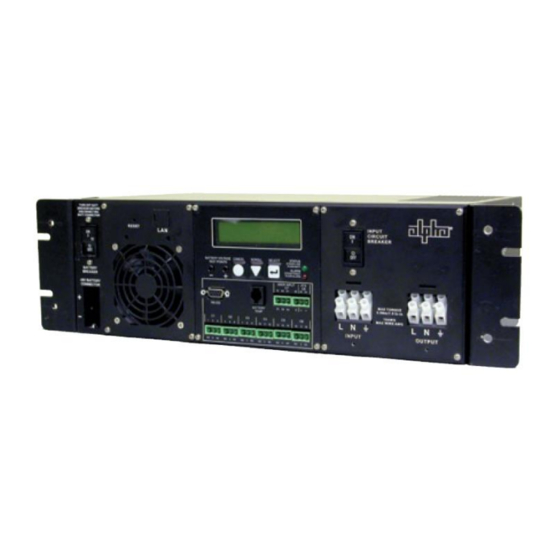
ELV/LV LED type traffic controller equipment. Figure 4-1: Alpha FXM Series UPS Unit Each Siemens UPS solution uses one of two FXM series UPS units, depending on the power requirements of the traffic intersection to be supported. -
Page 18: Universal Automatic Transfer Switch
-40°C to +74°C Table 4-2: UATS – Key Electrical Information Version Page 18 of 76 Status ISSUED Last Editor Ore Oluwatudimu TS008468 Date 31/01/2017 Document UPS Solution General Handbook Doc. No. 667/HB/47750/000 Name Copyright ã Siemens plc 2017 All Rights Reserved... -
Page 19: Lead Crystal Batteries
BH17 7ER 4.3 Lead Crystal Batteries Battery backup within the Siemens UPS solution is provided by banks of 55Ah 12V front terminal Lead Crystal batteries. Each bank consists of 4 of these batteries, creating a 48V 55Ah pack. Lead Crystal batteries have a greatly extended operating temperature range and a longer life expectancy when compared to their Lead Acid equivalents. -
Page 20: Sizing The Ups Solution
Figure 5-1: Battery Hold up times at 20°C and 0°C Version Page 20 of 76 Status ISSUED Last Editor Ore Oluwatudimu TS008468 Date 31/01/2017 Document UPS Solution General Handbook Doc. No. 667/HB/47750/000 Name Copyright ã Siemens plc 2017 All Rights Reserved... -
Page 21: Sizing Example
See Figure 5-2 on the following page. Version Page 21 of 76 Status ISSUED Last Editor Ore Oluwatudimu TS008468 Date 31/01/2017 Document UPS Solution General Handbook Doc. No. 667/HB/47750/000 Name Copyright ã Siemens plc 2017 All Rights Reserved... - Page 22 Battery Expansion Cabinet. Version Page 22 of 76 Status ISSUED Last Editor Ore Oluwatudimu TS008468 Date 31/01/2017 Document UPS Solution General Handbook Doc. No. 667/HB/47750/000 Name Copyright ã Siemens plc 2017 All Rights Reserved...
-
Page 23: Internal Cabling Scheme
UPS Connection Panel as part of the Installation process. See section 9.8 for details. Version Page 23 of 76 Status ISSUED Last Editor Ore Oluwatudimu TS008468 Date 31/01/2017 Document UPS Solution General Handbook Doc. No. 667/HB/47750/000 Name Copyright ã Siemens plc 2017 All Rights Reserved... -
Page 24: Battery Expansion Cabinet Internal Wiring
See section 10 for further information. Version Page 24 of 76 Status ISSUED Last Editor Ore Oluwatudimu TS008468 Date 31/01/2017 Document UPS Solution General Handbook Doc. No. 667/HB/47750/000 Name Copyright ã Siemens plc 2017 All Rights Reserved... -
Page 25: External Cabling Scheme
Version Page 25 of 76 Status ISSUED Last Editor Ore Oluwatudimu TS008468 Date 31/01/2017 Document UPS Solution General Handbook Doc. No. 667/HB/47750/000 Name Copyright ã Siemens plc 2017 All Rights Reserved... -
Page 26: Ups Fault / Alarm Relay Contacts
Infrastructure and Mobility, Traffic Solutions Sopers Lane, Poole, Dorset BH17 7ER For Siemens type controllers, please use the Master Switch Panel 300mA RCD Kit – 667/1/27117/000. A TT Earth Electrode test should be carried out as part of UPS commissioning. See section 11.2. -
Page 27: Further Ups Connectivity
NOTE: The SNMP (LAN) card is fitted to all Alpha FXM UPS units within Siemens UPS Solutions as standard. Version Page 27 of 76 Status ISSUED Last Editor Ore Oluwatudimu TS008468 Date 31/01/2017 Document UPS Solution General Handbook Doc. No. 667/HB/47750/000 Name Copyright ã Siemens plc 2017 All Rights Reserved... -
Page 28: Installation
Or similarly industrial self-adhesive tape. Insulation or Electrical tape is not acceptable. Version Page 28 of 76 Status ISSUED Last Editor Ore Oluwatudimu TS008468 Date 31/01/2017 Document UPS Solution General Handbook Doc. No. 667/HB/47750/000 Name Copyright ã Siemens plc 2017 All Rights Reserved... -
Page 29: Preparing And Installing The Reinforced Stool
2. Have the stool concreted into place in site in accordance with 667/HE/45950/000. See Figure 9-2. Version Page 29 of 76 Status ISSUED Last Editor Ore Oluwatudimu TS008468 Date 31/01/2017 Document UPS Solution General Handbook Doc. No. 667/HB/47750/000 Name Copyright ã Siemens plc 2017 All Rights Reserved... -
Page 30: Pulling And Gland Ducted Cables
CET plate. See section 7 for details on external cabling. Version Page 30 of 76 Status ISSUED Last Editor Ore Oluwatudimu TS008468 Date 31/01/2017 Document UPS Solution General Handbook Doc. No. 667/HB/47750/000 Name Copyright ã Siemens plc 2017 All Rights Reserved... -
Page 31: Fitting The Vented Cabinet Outer Case And Sealing The Base
Version Page 31 of 76 Status ISSUED Last Editor Ore Oluwatudimu TS008468 Date 31/01/2017 Document UPS Solution General Handbook Doc. No. 667/HB/47750/000 Name Copyright ã Siemens plc 2017 All Rights Reserved... -
Page 32: Fitting And Connecting The Battery Housing Module
‘top hat’ below. Version Page 32 of 76 Status ISSUED Last Editor Ore Oluwatudimu TS008468 Date 31/01/2017 Document UPS Solution General Handbook Doc. No. 667/HB/47750/000 Name Copyright ã Siemens plc 2017 All Rights Reserved... - Page 33 Battery Housing module below. Figure 9-6: Earth Connection between Battery Housing modules Version Page 33 of 76 Status ISSUED Last Editor Ore Oluwatudimu TS008468 Date 31/01/2017 Document UPS Solution General Handbook Doc. No. 667/HB/47750/000 Name Copyright ã Siemens plc 2017 All Rights Reserved...
-
Page 34: Mounting And Connecting The Ups Housing Module
Battery Housing module to reach the connector of the housing below. Version Page 34 of 76 Status ISSUED Last Editor Ore Oluwatudimu TS008468 Date 31/01/2017 Document UPS Solution General Handbook Doc. No. 667/HB/47750/000 Name Copyright ã Siemens plc 2017 All Rights Reserved... -
Page 35: Mounting And Connecting The Dc Housing Module
Version Page 35 of 76 Status ISSUED Last Editor Ore Oluwatudimu TS008468 Date 31/01/2017 Document UPS Solution General Handbook Doc. No. 667/HB/47750/000 Name Copyright ã Siemens plc 2017 All Rights Reserved... -
Page 36: Terminating External Cables Into The Ups Connection Panel
See section 7 for further details on external cable specification details. Version Page 36 of 76 Status ISSUED Last Editor Ore Oluwatudimu TS008468 Date 31/01/2017 Document UPS Solution General Handbook Doc. No. 667/HB/47750/000 Name Copyright ã Siemens plc 2017 All Rights Reserved... -
Page 37: Terminating External Cables Into The Dc Connection Panel
2. Plug the RJ45 jack into the Ethernet socket marked ‘LAN’ on the FXM UPS unit. See section 7.4 for cable specification details. Version Page 37 of 76 Status ISSUED Last Editor Ore Oluwatudimu TS008468 Date 31/01/2017 Document UPS Solution General Handbook Doc. No. 667/HB/47750/000 Name Copyright ã Siemens plc 2017 All Rights Reserved... -
Page 38: Fitting And Connecting The Batteries
Figure 9-10: Battery Terminals Connected with the Terminal Linking Bar Version Page 38 of 76 Status ISSUED Last Editor Ore Oluwatudimu TS008468 Date 31/01/2017 Document UPS Solution General Handbook Doc. No. 667/HB/47750/000 Name Copyright ã Siemens plc 2017 All Rights Reserved... -
Page 39: Fitting The Battery Temperature Sensor
4. Tidy away the Battery Temperature Sensor cable. Version Page 39 of 76 Status ISSUED Last Editor Ore Oluwatudimu TS008468 Date 31/01/2017 Document UPS Solution General Handbook Doc. No. 667/HB/47750/000 Name Copyright ã Siemens plc 2017 All Rights Reserved... -
Page 40: Isolation Switches
· UPS Supply Breaker (CB1) Figure 10-1: UATS Switches Version Page 40 of 76 Status ISSUED Last Editor Ore Oluwatudimu TS008468 Date 31/01/2017 Document UPS Solution General Handbook Doc. No. 667/HB/47750/000 Name Copyright ã Siemens plc 2017 All Rights Reserved... -
Page 41: Fxm Ups Unit
Input Circuit Breaker Figure 10-2: Alpha FXM UPS Circuit Breakers Version Page 41 of 76 Status ISSUED Last Editor Ore Oluwatudimu TS008468 Date 31/01/2017 Document UPS Solution General Handbook Doc. No. 667/HB/47750/000 Name Copyright ã Siemens plc 2017 All Rights Reserved... -
Page 42: Commissioning
APPENDIX D – UPS Commissioning Certificate. The certificate must then be presented to the customer as part of the installation handover process. A copy must also be retained by Siemens Traffic Solutions. A copy should also be kept within the UPS cabinet for reference during maintenance actions. -
Page 43: Putting The Ups Solution In Bypass
7. Wait for the UPS Unit to display ‘LINE’. Version Page 43 of 76 Status ISSUED Last Editor Ore Oluwatudimu TS008468 Date 31/01/2017 Document UPS Solution General Handbook Doc. No. 667/HB/47750/000 Name Copyright ã Siemens plc 2017 All Rights Reserved... -
Page 44: Testing The Ups Battery Support Function
8. Check that the red ALARM LED is not lit or flashing Commissioning of the UPS Solution is now complete. Version Page 44 of 76 Status ISSUED Last Editor Ore Oluwatudimu TS008468 Date 31/01/2017 Document UPS Solution General Handbook Doc. No. 667/HB/47750/000 Name Copyright ã Siemens plc 2017 All Rights Reserved... -
Page 45: Ups System Operation
12.2.1 Fault / Alarm Relay Contacts The UPS Solution provides six relay outputs via the UPS Connection Panel that can be cabled directly to the traffic controller cabinet for fault monitoring with Siemens UTMC or RMS systems. See section 12.2.2 for details. - Page 46 All possible Alarm Contact triggers are listed in APPENDIX B – FXM UPS Faults and Alarms Version Page 46 of 76 Status ISSUED Last Editor Ore Oluwatudimu TS008468 Date 31/01/2017 Document UPS Solution General Handbook Doc. No. 667/HB/47750/000 Name Copyright ã Siemens plc 2017 All Rights Reserved...
-
Page 47: Fault Monitoring Using Siemens Rms And Utmc Systems
Review the controller and any OTU/OMU configurations supplied by the customer to determine the connections that need to be made. Figure 12-1: Fault Monitoring Connectivity Example C6 is not to be used with Siemens traffic equipment. See section 12.2.1 Version Page 47 of 76... -
Page 48: Communicating With The Ups Solution
/ alarm information in the following format. Version Page 48 of 76 Status ISSUED Last Editor Ore Oluwatudimu TS008468 Date 31/01/2017 Document UPS Solution General Handbook Doc. No. 667/HB/47750/000 Name Copyright ã Siemens plc 2017 All Rights Reserved... - Page 49 Alpha FXM UPS Operating Manual – 667/HB/47760/000. Version Page 49 of 76 Status ISSUED Last Editor Ore Oluwatudimu TS008468 Date 31/01/2017 Document UPS Solution General Handbook Doc. No. 667/HB/47750/000 Name Copyright ã Siemens plc 2017 All Rights Reserved...
-
Page 50: Lan Interface
The UPS Solution’s operating mode and fault / alarm flags are always displayed at the top of each page for easy system monitoring. Version Page 50 of 76 Status ISSUED Last Editor Ore Oluwatudimu TS008468 Date 31/01/2017 Document UPS Solution General Handbook Doc. No. 667/HB/47750/000 Name Copyright ã Siemens plc 2017 All Rights Reserved... - Page 51 GUI is available within the Alpha FXM UPS Operating Manual – 667/HB/47760/000. http://www.alpha.ca/web2/service-and-support/support/software-firmware-downloads Version Page 51 of 76 Status ISSUED Last Editor Ore Oluwatudimu TS008468 Date 31/01/2017 Document UPS Solution General Handbook Doc. No. 667/HB/47750/000 Name Copyright ã Siemens plc 2017 All Rights Reserved...
-
Page 52: Battery Charging
This is voltage is periodically raised to 56Vdc or above as the UPS unit looks for a battery connection. Version Page 52 of 76 Status ISSUED Last Editor Ore Oluwatudimu TS008468 Date 31/01/2017 Document UPS Solution General Handbook Doc. No. 667/HB/47750/000 Name Copyright ã Siemens plc 2017 All Rights Reserved... -
Page 53: Temperature De-Rating
1520 W/VA Table 12-6: Maximum Output Power against Ambient Temperature Version Page 53 of 76 Status ISSUED Last Editor Ore Oluwatudimu TS008468 Date 31/01/2017 Document UPS Solution General Handbook Doc. No. 667/HB/47750/000 Name Copyright ã Siemens plc 2017 All Rights Reserved... -
Page 54: Battery Charging
5) adjusted for ambient cabinet temperatures of +20°C, 0°C and -25°C. 12.6 Generators 12.6.1 The Generator Connect Feeder Pillar As stated in section 2.4, a diesel generator must be connected via the Siemens Generator Connect Feeder Pillar as shown below. Figure 12-5: Generator Connect Feeder Pillar... -
Page 55: Generator Selection
Sopers Lane, Poole, Dorset BH17 7ER 12.6.2 Generator Selection Generators to be used with the Siemens UPS solution must adhere to the following conditions. WARNING: Using a Generator that does not meet all the conditions below is a major safety risk and may also cause permanent damage to the UPS solution. -
Page 56: Connecting A Generator To The Ups Solution
6. Remove the connecting cable then close and lock the pillar. Version Page 56 of 76 Status ISSUED Last Editor Ore Oluwatudimu TS008468 Date 31/01/2017 Document UPS Solution General Handbook Doc. No. 667/HB/47750/000 Name Copyright ã Siemens plc 2017 All Rights Reserved... -
Page 57: Maintenance
Cumulative inverter time · Cumulative kWh output · Estimated battery support Version Page 57 of 76 Status ISSUED Last Editor Ore Oluwatudimu TS008468 Date 31/01/2017 Document UPS Solution General Handbook Doc. No. 667/HB/47750/000 Name Copyright ã Siemens plc 2017 All Rights Reserved... -
Page 58: Maintenance Bypass Switching
See section 4.2 for more information on the UATS. Version Page 58 of 76 Status ISSUED Last Editor Ore Oluwatudimu TS008468 Date 31/01/2017 Document UPS Solution General Handbook Doc. No. 667/HB/47750/000 Name Copyright ã Siemens plc 2017 All Rights Reserved... -
Page 59: Switching Off The Ups Solution
The UPS Solution will now be completely isolated from Mains and Batteries. Version Page 59 of 76 Status ISSUED Last Editor Ore Oluwatudimu TS008468 Date 31/01/2017 Document UPS Solution General Handbook Doc. No. 667/HB/47750/000 Name Copyright ã Siemens plc 2017 All Rights Reserved... -
Page 60: First Line Maintenance
22. Check the UPS goes into LINE mode and check the alarms. Version Page 60 of 76 Status ISSUED Last Editor Ore Oluwatudimu TS008468 Date 31/01/2017 Document UPS Solution General Handbook Doc. No. 667/HB/47750/000 Name Copyright ã Siemens plc 2017 All Rights Reserved... -
Page 61: Replacing A Battery Pack
4. Repeat this last step with Batteries 3 and 4. Version Page 61 of 76 Status ISSUED Last Editor Ore Oluwatudimu TS008468 Date 31/01/2017 Document UPS Solution General Handbook Doc. No. 667/HB/47750/000 Name Copyright ã Siemens plc 2017 All Rights Reserved... - Page 62 Finally check that there are no alarms active on the UPS and that the UPS is in Line mode. Version Page 62 of 76 Status ISSUED Last Editor Ore Oluwatudimu TS008468 Date 31/01/2017 Document UPS Solution General Handbook Doc. No. 667/HB/47750/000 Name Copyright ã Siemens plc 2017 All Rights Reserved...
-
Page 63: Replacing An Alpha Uats Unit
Any queries should be directed to the Service Logistics Manager on (01530) 258181. Version Page 63 of 76 Status ISSUED Last Editor Ore Oluwatudimu TS008468 Date 31/01/2017 Document UPS Solution General Handbook Doc. No. 667/HB/47750/000 Name Copyright ã Siemens plc 2017 All Rights Reserved... -
Page 64: Disposal
All Traffic Solutions, Siemens depots operates an Environmental Management System (EMS). In accordance with its Environmental Policy Siemens applies the Waste Hierarchy when managing waste, segregating waste into a number of waste streams to optimise the re-use/recycling carried out by the approved waste contractors that take the waste away. - Page 65 Generator Connect Feeder Pillar – GREY 667/7/45043/200 Generator Connect Feeder Pillar – BLACK Version Page 65 of 76 Status ISSUED Last Editor Ore Oluwatudimu TS008468 Date 31/01/2017 Document UPS Solution General Handbook Doc. No. 667/HB/47750/000 Name Copyright ã Siemens plc 2017 All Rights Reserved...
- Page 66 Figure A-0-1: Estimates of UPS Solution Performance at +20°C Version Page 66 of 76 Status ISSUED Last Editor Ore Oluwatudimu TS008468 Date 31/01/2017 Document UPS Solution General Handbook Doc. No. 667/HB/47750/000 Name Copyright ã Siemens plc 2017 All Rights Reserved...
- Page 67 Figure A-0-2: Estimates of UPS Solution Performance at 0°C Version Page 67 of 76 Status ISSUED Last Editor Ore Oluwatudimu TS008468 Date 31/01/2017 Document UPS Solution General Handbook Doc. No. 667/HB/47750/000 Name Copyright ã Siemens plc 2017 All Rights Reserved...
- Page 68 Figure A-0-3: Estimates of UPS Solution Performance at -25°C Version Page 68 of 76 Status ISSUED Last Editor Ore Oluwatudimu TS008468 Date 31/01/2017 Document UPS Solution General Handbook Doc. No. 667/HB/47750/000 Name Copyright ã Siemens plc 2017 All Rights Reserved...
- Page 69 Default value of 47V relating to 40% SOC. Triggers C1. See section 12.2.1 See section 10.3 See section 12.3.3 Version Page 69 of 76 Status ISSUED Last Editor Ore Oluwatudimu TS008468 Date 31/01/2017 Document UPS Solution General Handbook Doc. No. 667/HB/47750/000 Name Copyright ã Siemens plc 2017 All Rights Reserved...
- Page 70 APPENDIX C – Hardware Datasheets Alpha FXM Series UPS Unit Version Page 70 of 76 Status ISSUED Last Editor Ore Oluwatudimu TS008468 Date 31/01/2017 Document UPS Solution General Handbook Doc. No. 667/HB/47750/000 Name Copyright ã Siemens plc 2017 All Rights Reserved...
- Page 71 Infrastructure and Mobility, Traffic Solutions Sopers Lane, Poole, Dorset BH17 7ER Version Page 71 of 76 Status ISSUED Last Editor Ore Oluwatudimu TS008468 Date 31/01/2017 Document UPS Solution General Handbook Doc. No. 667/HB/47750/000 Name Copyright ã Siemens plc 2017 All Rights Reserved...
- Page 72 Sopers Lane, Poole, Dorset BH17 7ER Alpha Universal Automatic Transfer Switch (UATS) Version Page 72 of 76 Status ISSUED Last Editor Ore Oluwatudimu TS008468 Date 31/01/2017 Document UPS Solution General Handbook Doc. No. 667/HB/47750/000 Name Copyright ã Siemens plc 2017 All Rights Reserved...
- Page 73 Infrastructure and Mobility, Traffic Solutions Sopers Lane, Poole, Dorset BH17 7ER Version Page 73 of 76 Status ISSUED Last Editor Ore Oluwatudimu TS008468 Date 31/01/2017 Document UPS Solution General Handbook Doc. No. 667/HB/47750/000 Name Copyright ã Siemens plc 2017 All Rights Reserved...
- Page 74 Betta Batteries 6CNFT-55 12V 55Ah Front Terminal Lead Crystal Battery Version Page 74 of 76 Status ISSUED Last Editor Ore Oluwatudimu TS008468 Date 31/01/2017 Document UPS Solution General Handbook Doc. No. 667/HB/47750/000 Name Copyright ã Siemens plc 2017 All Rights Reserved...
- Page 75 Infrastructure and Mobility, Traffic Solutions Sopers Lane, Poole, Dorset BH17 7ER Version Page 75 of 76 Status ISSUED Last Editor Ore Oluwatudimu TS008468 Date 31/01/2017 Document UPS Solution General Handbook Doc. No. 667/HB/47750/000 Name Copyright ã Siemens plc 2017 All Rights Reserved...
-
Page 76: Version
Input MCB switched ON? e. Traffic signals remain lit as normal? Name (Print) ………………………………………………………………………………….… Signature ……………………………………………………………………………………….. Date carried out………..………………………………………………………………………. One copy of this form to be left with the client and one copy retained by Siemens Version Page 76 of 76 Status ISSUED...
Need help?
Do you have a question about the 667/HB/47750/000 and is the answer not in the manual?
Questions and answers