Table of Contents
Advertisement
Quick Links
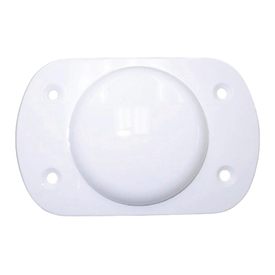
The GPS-302L-A40 is an active antenna designed to operate at the GPS L1 and L2 frequencies, 1575.42
and 1227.60 MHz and across the L-Band from 1525 to 1560 MHz. This guide provides the information
needed to install and use the antenna.
ADDITIONAL EQUIPMENT REQUIRED
• A device with an antenna input port that both receives the RF signal and provides 3.8 to 6.0 VDC to
the antenna is required to set up the GPS-302L-A40. (NovAtel GNSS receivers provide the neces-
sary power through their antenna RF connectors.)
•
Coaxial cable with a male TNC connector
INSTALLING THE ANTENNA
The integrator of this antenna is responsible for ensuring antenna installation meets all the
overall integrated system requirements.
Refer to Section 307 of
AC%2043.13-2B.pdf
Both the input DC power and the output RF signal flow over a single coaxial cable connected to the
antenna's TNC female connector.
The antenna is attached to a surface by means of an ARINC-743 Bolt Pattern.
Four screws pass through the housing of the antenna.
Install the antenna as follows:
1. Place the o-ring into the groove on the antenna base (o-ring supplied).
User-supplied o-ring grease can be used to hold the o-ring in the groove during installation.
2. Drill the mounting holes and the connector hole on the surface. Refer to the Mechanical Drawings
section of this guide for details on the ARINC-743 mounting pattern.
www.faa.gov/documentLibrary/media/Advisory_Circular/
for information about antenna bonding in aircraft applications.
GPS-302L-A40
USER GUIDE
GM-14915162
Rev 2
February 2019
1
Advertisement
Table of Contents

Related Manuals for Novatel GPS-302L-A40


Summary of Contents for Novatel GPS-302L-A40
- Page 1 Rev 2 February 2019 The GPS-302L-A40 is an active antenna designed to operate at the GPS L1 and L2 frequencies, 1575.42 and 1227.60 MHz and across the L-Band from 1525 to 1560 MHz. This guide provides the information needed to install and use the antenna.
- Page 2 3. Attach the antenna to the surface using the four mounting screws supplied. The o-ring will compress and create a seal between the surface and the antenna. Ref. # Description Antenna Countersink screws Mounting surface O-ring Drilled mounting holes 4. Remove the dust cap from the antenna’s TNC connector. 5.
- Page 3 SPECIFICATIONS section of this guide. All NovAtel GNSS receivers provide the necessary power through their antenna RF connectors. The graphic above shows examples of where the GPS-302L-A40 antenna may be located on an aircraft or vehicle (not to scale).
- Page 4 SPECIFICATIONS L1: 1575.42 ±12 MHz Operational band (typical) L2: 1227.60 ±12 MHz LB: 1542.50 ±17.5 MHz L1: +4.1 dBic Gain at zenith ( = 90°) (min) L2: +3.9 dBic LB: +5.7 dBic LNA gain (typical) 40 dB ±3dB Polarization Right-hand circular Noise figure (typical) 3 dB...
- Page 5 MECHANICAL DRAWINGS Dimensions are in inches followed by [mm]...
- Page 6 Customer Service can be found on the last panel of this guide. WEEE If you purchased a GPS-302L-A40 antenna in Europe, return it to your dealer or supplier at the end of its life. The objectives of the European Community's environment policy are, in particular, to preserve, protect and improve the quality of the environment, protect human health and utilise natural resources prudently and rationally.
- Page 7 QUESTIONS OR COMMENTS If you have any questions or comments, please log a support request with NovAtel Customer Support using one of the following methods: Log a Case and Search Knowledge: Website: www.novatel.com/support Log a Case, Search Knowledge and View Your Case History: (login access required) Web Portal: https://novatelsupport.force.com/community/login...
- Page 8 © Copyright 2019 NovAtel Inc. All rights reserved. Unpublished rights reserved under international copyright laws.
Need help?
Do you have a question about the GPS-302L-A40 and is the answer not in the manual?
Questions and answers