Table of Contents
Advertisement
Quick Links
Advertisement
Table of Contents

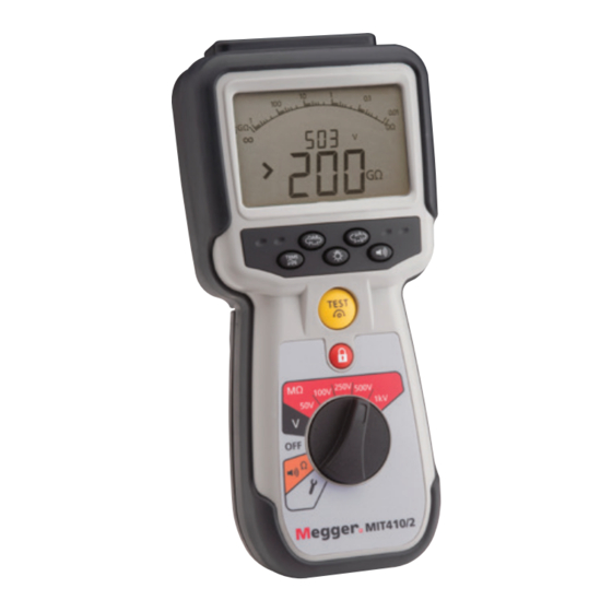
Summary of Contents for Megger MIT417
- Page 1 MIT415 / MIT417 Insulation and continuity tester User Guide...
-
Page 2: Safety Warnings
Safety warnings Safety Warnings and Precautions must be read and understood before the instrument is used. They must be observed during use. The circuit under test must be switched off, de-energised, securely isolated and proved dead before test connections are made when carrying out insulation and continuity tests. -
Page 3: Symbols Used On The Instrument
Symbols used on the instrument: Caution: risk of electric shock Caution: refer to accompanying notes Displayed on the LCD during an insulation test, warns that a hazardous voltage may exist at the test lead probes also observe voltage discharges to a safe level. On battery cover see section 2.0 notes 10 and 11. -
Page 4: Lcd Display
LCD Display Auxiliary digital display Continuity indicator Battery Lock indicator condition indicator Warning-refer to user guide TRMS indicator Out of range indicator Lead null indicator Audible alarm indicator Figure 3 LCD display In continuity mode, if a voltage greater than 25 V exists, testing will be automatically inhibited and voltage measurement will be displayed. -
Page 5: Standard Insulation Resistance Testing
performing an insulation resistance test, and ensure all necessary health and safety precautions are observed. Automatic Discharge: Capacitive circuits are automatically discharged when the test button is released following an insulation test. The circuit under test must be completely de-energised and securely isolated before test connections are made. - Page 6 DAR is the ratio between the insulation resistance values at 30seconds (assigned t1) and at 60 second interval (assigned t2). i.e. after 30seconds and 60seconds. DAR = 60 second value/30 second value During all insulation tests the symbol will flash indicating that a test voltage is present.
-
Page 7: Setup Options
display indicates the actual test current (e.g. 205 mA. The maximum is defined in setup menu. Note: The test current displayed is the actual test current used during the test, which will depend on the resistance of the circuit under test. Resistance measurements (kΩ... -
Page 8: Battery Disposal
The crossed out wheeled bin symbol on the instrument and on the batteries is a reminder not to dispose of them with general waste at the end of their life. Megger is registered in the UK as a producer of electrical and electronic equipment. Registration number WEE/H0146QT. -
Page 9: Preventive Maintenance
Insulation Nominal test voltages for MIT415: 10 V, 25 V, 50 V, 100 V, 250 V, 500 V Nominal test voltages for MIT417: 10 V, 25 V, 50 V, 100 V, 250 V, 500 V, 1000 V Range full scale accuracy All ranges ±2% ±2 digits up to 100 MΩ. -
Page 10: Voltage Range
Leakage current: 10% ±3 digits Voltage display: 3% ±3 digits ±0.5% of rated voltage Dielectric absorption Ratio (DAR): 60sec / 30sec ratio Notes: All ranges measure from 0,00 MΩ upwards. Above specifications only apply when high quality silicone leads are being used. Continuity EN61557 operating range: 0,01 Ω... -
Page 11: Safety Protection
Dimensions 220 x 92 x 50 mm (8.66 in x 3.63 in x 1.97 in) Weight 590 gms, 775 gms with boot (20.73 oz (27.22 oz) Fuse Use only a 500 mA (FF) 1000 V 32 x 6 mm ceramic fuse of high breaking capacity HBC 50 kA minimum. - Page 12 Accessories Includes accessories 2 wire test lead set and crocodile clips 1002-001 SP5 Remote switch probe 1002-774 Calibration certificate Rubber boot 6231-802 Instrument case 5410-420 User guide 2000-171 Optional accessories and replacements Fused 2 wire test lead set and crocodile clips 1002-015...
- Page 13 Approved Repair Companies Megger operates fully traceable repair and calibration facilities complemented by a network of approved repair and calibration companies, to offer excellent in-service care for your Megger products. Megger’s streamlined Returns Authorization system ensures your product is expected and enables you to track its progress on-line.
- Page 14 T +1 416 298 6770 F +1 416 298 0848 E casales@megger.com Megger products are distributed in 146 countries worldwide. This instrument is manufactured in the United Kingdom. The company reserves the right to change the specification or design without prior notice.


Need help?
Do you have a question about the MIT417 and is the answer not in the manual?
Questions and answers