Table of Contents
Advertisement
Quick Links
INSTALLATION INSTRUCTIONS
V
ENMAR MODELS
VB0313
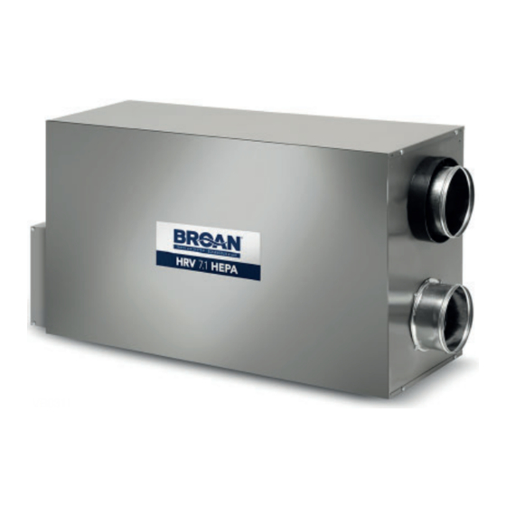
EVO5 700 HRV HEPA
VB0312
EVO5 500 HRV
* These products earned the ENERGY STAR
Canada and the US EPA. They meet ENERGY STAR requirements only when used in Canada.
AND USER GUIDE
®
R
!
ESIDENTIAL INDOOR USE ONLY
READ AND SAVE THESE INSTRUCTIONS
B
VB0311
VB0310
by meeting strict energy efficiency guidelines set by Natural Resources
ROAN MODELS
HRV 7.1 HEPA
HRV 5.1
!
20846 rev. 07
Advertisement
Table of Contents

Related Manuals for Broan VB0313


Summary of Contents for Broan VB0313
- Page 1 INSTALLATION INSTRUCTIONS AND USER GUIDE ENMAR MODELS ROAN MODELS VB0313 VB0311 EVO5 700 HRV HEPA HRV 7.1 HEPA VB0312 VB0310 EVO5 500 HRV HRV 5.1 * These products earned the ENERGY STAR ® by meeting strict energy efficiency guidelines set by Natural Resources Canada and the US EPA.
- Page 2 ABOUT THIS GUIDE First, we want to congratulate you on your purchase of this excellent unit which will allow you and your family to enjoy clean and healthy air throughout your home for years to come! Since this publication covers several models, the illustrations are typical ones. Some details of your unit may be slightly different than the ones shown.
-
Page 3: Table Of Contents
ABLE OF ONTENTS 1. T ..........4 YPICAL NSTALLATIONS 1.1 F... -
Page 4: Typical Installations
In every case, bathroom fans and a range hood could be used to exhaust stale air. However, please note that an optional bathroom installation kit (no. IKBV1000 for Venmar units and no. IKBB1000 for Broan units) is available for house where there is no bathroom fans. -
Page 5: Dimensions
2. D IMENSIONS 2.1 EVO5 700 HRV HEPA HRV 7.1 HEPA UNITS " 11¼" 33" " 12 3/ " 39 3/ " VK0121A 2.2 EVO5 500 HRV HRV 5.1 UNITS ” 11¼” 31” ” 12 ³/ ” ” VK0120A ® 2.3 J OIST OPENING REQUIRED FOR ANDEM... -
Page 6: Installation
3. I NSTALLATION 3.1 I NSPECT THE ONTENT OF THE NOTE: Before proceeding to the installation, check the content of the box. If items are missing or damaged, contact the manufacturer. Remove all packaging material from the unit. • Inspect the exterior of the unit for shipping damage. Ensure that there is no damage to the door, door latches, ports, power cord, etc. -
Page 7: Installation
NSTALLATION 3.2 I NSTALLATION OOLS AND ATERIAL The installation kit needed to perform most installations is IKSV1000 for Venmar units and IKSB1000 for Broan units. Following are the tools and material needed: • Measuring tape • Phillips no. 2 or Robertson no. 2 screwdriver •... - Page 8 3. I ’ NSTALLATION CONT 3.5 I NSTALLING NSULATED UCTS AND IFFUSERS 3.5.1 F 1.1) ULLY UCTED YSTEM AS ILLUSTRATED IN ECTION WARNING Never install a stale air exhaust diffuser in a closed room where a combustion device operates, such as a gas furnace, a gas water heater or a fireplace.
-
Page 9: Installing Non -Insulated
3. I ’ NSTALLATION CONT 3.5 I ’ NSTALLING NSULATED UCTS AND IFFUSERS CONT 3.5.1 F 1.1) ’ ULLY UCTED YSTEM AS ILLUSTRATED IN ECTION CONT OW TO CONNECT THE FLEXIBLE DUCTS TO THE UNIT PORTS IGHT SIDE OF THE UNIT Both flexible ducts attached to the diffusers must be connected to the bottom ports of the unit. -
Page 10: Onnection To
3. I ’ NSTALLATION CONT 3.6 I NSTALLING NSULATED LEXIBLE UCTS CAUTION Make sure the vapor barrier on the insulated ducts does not tear during installation to avoid condensation within the ducts. ® Use the following procedure for connecting the insulated flexible ducts to the Tandem transition (exhaust air to outside and fresh air from outside). -
Page 11: Connection To The Nstalling Ual Xterior
3. I ’ NSTALLATION CONT 3.6 I ’ NSTALLING NSULATED LEXIBLE UCTS CONT 3.6.2 C ONNECTION TO THE UNIT PORTS Use the following procedure for connecting the insulated flexible ducts to the unit ports (exhaust air to outside and fresh air from outside). -
Page 12: Connecting Tandem
3. I ’ NSTALLATION CONT 3.7 I ’ NSTALLING XTERIOR CONT 3.7.3 C ONNECTING ANDEM RANSITION TO XTERIOR XHAUST AIR TO OUTSIDE DUCT ON TOP Using a jig saw, cut a 6” diameter hole in the exterior wall and slide the single end of the Tandem transition in it. -
Page 13: Connecting The Drain
3. I ’ NSTALLATION CONT 3.8 C ONNECTING THE RAIN IE WRAP ± 12” ± 12” ± 1” VD0513A Cut two sections of plastic tubing, approximately VD0308A 12” long, and connect each one to both inner drain Run the tube to the floor fittings located under the unit as shown. - Page 14 4. C ’ ONTROLS CONT 4.3 M ONTROL NSTALLATION These units should be controlled using a main wall control (included). NOTE: If an optional auxiliary control is used, if activated, this auxiliary control will override the main control operation. WARNING Always disconnect the unit before making any connections.
-
Page 15: Main Wall Controli
4. C ’ ONTROLS CONT 4.3 M ’ ONTROL NSTALLATION CONT Splice back the end of the cable to access the 4 wires. Strip the end of each wire. Connect RED wire GREEN wire each wire to its corresponding terminal: YELLOW wire to “Y’’ , RED wire to “R’’ , GREEN YELLOW wire BLACK wire wire to “G’’... -
Page 16: Wall Control
The included wall control is 40405 (intented for EVO5 500 HRV and EVO5 700 HRV HEPA Venmar units only) or 40410 (intented for HRV 5.1 and HRV 7.1 HEPA Broan units only). The wall control is in OFF mode when power is applied for the first time. -
Page 17: 4.6.2 Turbo F
4. C ’ ONTROLS CONT 4.6 M ’ ONTROL CONT 4.6.1 O ’ PERATION ODES CONT ECO M The ventilation unit exchanges air intermittently on a one-hour cycle as follows: a 10-minute cycle of air exchange, then 50 minutes on recirculation on low speed (or OFF for 50 minutes, then 10 minutes on low speed air exchange, see section 4.6.3). NOTE: The outdoor temperature value displayed during ECO recirculation or ECO off cycle comes from the reading while the unit is performing air exchange (first or last part of ECO mode cycle). -
Page 18: Changing
4. C ’ ONTROLS CONT 4.6 M ’ ONTROL CONT 4.6.3 C RECIRCULATION AUTO ECO M HANGING ODES NOTE: Prior to perform this setting, Press hold simultaneously Letters rEC and circled arrows are the wall control must be ON. MODE keys during flashing (default configuration setting). -
Page 19: Ow To Hange
4. C ’ ONTROLS CONT 4.6 M ’ ONTROL CONT 4.6.6 H AUTO M OW TO HANGE INIMUM AND AXIMUM XCHANGE EMPERATURE IMITS FOR ODES The minimum and maximum temperature limits for air exchange allow to stop air exchange with the outside for better comfort in the house. -
Page 20: Maintenance
5. M AINTENANCE WARNING Risk of electric shock. Before performing any maintenance, always turn off and disconnect the unit from its power source. Refer to the illustration at right to identify the inner removable parts of your unit: A. Heat recovery core B. -
Page 21: Regular Maintenance
5. M ’ AINTENANCE CONT 5.2 R EGULAR AINTENANCE Perform this maintenance on the unit every time the wrench icon appears on wall control screen. Turn the unit OFF and unplug it. VD0005 Unlatch and tilt the door (A) from the unit base, then lift it up (B) and set aside. CAUTION In order to prevent damages to the door hooks, do not open completely the unit door;... -
Page 22: Annual Maintenance
5. M ’ AINTENANCE CONT 5.2 R ’ EGULAR AINTENANCE CONT Reinstall the heat recovery core with its filters. For EVO5 700 HRV HEPA and HRV 7.1 HEPA units only: The heat recovery core must be reinstalled BEFORE the core bracket. -
Page 23: Troubleshooting
7. T ROUBLESHOOTING If the unit does not work properly, reset the unit by unplugging it for one minute and then replug it. If it is still not working properly, refer to table below. Problems You should try this The error code E1 or E3 appears on wall control •... -
Page 24: Warranty
8. W ARRANTY WARRANTY - WHOLE-HOUSE AIR EXCHANGER The manufacturer warrants to the original consumer purchaser of its products, that such products will be free from defects for the period stated below, from date of original purchase. The WHOLE-HOUSE AIR EXCHANGER is fully protected by a 1-year warranty on all parts and labor in workshop.
Need help?
Do you have a question about the VB0313 and is the answer not in the manual?
Questions and answers