Table of Contents
Advertisement
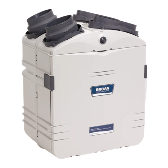
INSTALLATION INSTRUCTIONS
HEPA 2000*
HF 2.0*
HEPA 1000*
HF 1.0*
VB0061
*Patents pending
NOTE: HEPA 4000 model available in United States only.
READ AND SAVE THESE INSTRUCTIONS
INSTALLER: LEAVE THIS MANUAL WITH THE HOMEOWNER.
HOMEOWNER: USE AND CARE INFORMATION
AND USER MANUAL
RESIDENTIAL USE ONLY
ON PAGES 28 and 32 to 36.
M O D E L S
HEPA 4000*
HEPA 3000*
HF 3.0*
04313
rev C
Advertisement
Table of Contents

Related Manuals for Broan HEPA 1000


Summary of Contents for Broan HEPA 1000
-
Page 1: Installation Instructions
INSTALLATION INSTRUCTIONS AND USER MANUAL HEPA 2000* HF 2.0* HEPA 1000* HF 1.0* VB0061 *Patents pending NOTE: HEPA 4000 model available in United States only. READ AND SAVE THESE INSTRUCTIONS INSTALLER: LEAVE THIS MANUAL WITH THE HOMEOWNER. HOMEOWNER: USE AND CARE INFORMATION ON PAGES 28 and 32 to 36. -
Page 2: About This Manual
We welcome any suggestions you may have concerning this manual and/or the unit, and we would appreciate hearing your comments on ways to better serve you. Please contact us by phone at one of the following numbers: Exclusively for all HF Models: Broan-NuTone Canada Inc. 1 866 737-7770 WARNING CAUTION Exclusively for all HEPA Models: Venmar Ventilation inc. -
Page 3: About These Units
9’10” (3 m) from this plenum connection to the furnace. For HEPA 1000 and HF 1.0 units only, the distance must be not closer than 2’ (0.61 m). -
Page 4: Table Of Contents
2.3.3 Return-to-Return Installation ....14 IMENSIONS HEPA 1000 and HF 1.0 Units ....15 HEPA 2000, HF 2.0, HEPA 3000, HF 3.0 and HEPA 4000 units . - Page 5 TABLE DES MATIÈRES Installation des conduit flexibles isolés ..23 4.6.1 Raccordement à la transition Tandem® ..23 4.6.2 Raccordement aux bouches ovales de 5”à 6” . .24 Installation de la bouche extérieure double ..25 4.7.1 Assemblage de la bouche extérieure double .
-
Page 6: Before Starting
NOTE: For more details, see Point 5.3 in Section 5 INSTALL THE UNIT. In every case, bathroom fans and a range hood should be used to exhaust stale air. Also, for homes with more than one level, we recommend one exhaust register at the highest level. -
Page 7: Hepa 1000 And Hf 1.0 Unit Installations
2. TYPICAL INSTALLATIONS 2.1 H 1000 2.1.1 S TAND LONE Stale air is drawn to the unit by the register located at the highest level of the house. Filtered air is supplied by the register located at the lowest level. See figure below. -
Page 8: Central Draw Point
NOTE: Home with multiple forced air systems should have 1 unit on each system. VH0038 Do not connect the unit (HEPA 1000 or HF 1.0) on any forced air system supply duct. Connect it only to the air return duct. Do not install duct or duct connector directly above the forced air unit or not less than 2’... -
Page 9: Return-To-Return Installation
NOTE: Home with multiple forced air systems should have 1 unit on each system. Do not connect the unit (HEPA 1000 or HF 1.0) on any forced air system supply duct. Connect it only to the air return duct. Do not install duct or duct connector directly above the forced air unit or not less than 2’... -
Page 10: Typical Installations
2. TYPICAL INSTALLATIONS 2.2 I NSTALLATION FOR 2.2.1 G EOGRAPHICAL The HEPA 4000 unit was created to meet specific requirements related to geographic locations. Take a look on the map below. The shaded area shows where the HEPA 4000 can be installed. HELENA OLYMPIA SALEM... -
Page 11: Hepa 4000 Attic Installation
2. TYPICAL INSTALLATIONS 2.2 I NSTALLATION FOR 2.2.2 HEPA 4000 A All 3 types of installation can be used in the attic (Stand Alone, Central Draw Point or Return-Return). The example shown below is a Return-Return installation (connection to a forced air system). Due to the potential temperature difference between the attic and the rest of the house, all unit ducts must be insulated. -
Page 12: Stand Alone
2. TYPICAL INSTALLATIONS 2.3 HEPA 2000, HF 2.0, HEPA 3000, HF 3.0 NSTALLATIONS 2.3.1 S TAND LONE A portion of stale air (coming from the register located at the highest level of the house) is exhausted to the outside and the rest is drawn to the unit. Outside fresh air is blended with interior air and then filtered. -
Page 13: Installations
2. TYPICAL INSTALLATIONS 2.3 HEPA 2000, HF 2.0, HEPA 3000, HF 3.0 NSTALLATIONS CONT 2.3.2 C ENTRAL A portion of stale air (coming from the register located in the highest level of the house) is exhausted to the outside and the rest is drawn to the unit. Outside fresh air is blended with interior air and then filtered. -
Page 14: Hepa 2000, Hf 2.0, Hepa 3000, Hf
2. TYPICAL INSTALLATIONS 2.3 HEPA 2000, HF 2.0, HEPA 3000, HF 3.0 NSTALLATIONS CONT 2.3.3 R ETURN A portion of stale air is exhausted to the outside and the rest is drawn to the unit. Outside fresh air is blended with interior air and then filtered. This filtered air is supplied to the return (plenum) of the forced air unit. -
Page 15: Dimensions
3. DIMENSIONS 3.1 HEPA 1000 22.9'' (581 mm) VK0047 FRONT VIEW 3.2 HEPA 2000, HF 2.0, HEPA 3000, HF 3.0 22.9'' (581 mm) VK0048 FRONT VIEW HF 1.0 U NITS 29'' (737 mm) 29.4'' (748 mm) - 15 - 17.8''... -
Page 16: Mounting And Servicing Considerations
3. DIMENSIONS (CONT’D) 3.3 M OUNTING AND • The two following pictures are showing the minimum clearance needed to open the door completely. 8” (203 mm) 22.5” (572 mm) VD0117 NOTE: A minimum of 8” (203 mm) clearance from any obstruction on top of the unit is required for the ductwork radius turn. -
Page 17: Install The Unit
• Close to an exterior wall, so as to limit the length of the insulated flexible duct to and from the unit (not necessary for HEPA 1000 and HF 1.0 units). • Away from hot chimneys and other fire hazards. -
Page 18: Vertical Position
According to your needs, you can install the unit either in vertical or horizontal position. ERTICAL POSITION LL MODELS VD0074 ORIZONTAL POSITION RIGHT SIDE HEPA 1000, HF 1.0 ODELS HEPA 2000, HF 2.0 ORIZONTAL POSITION LEFT SIDE HEPA 4000 LL MODELS... -
Page 19: Planning Of The Ductwork
• Keep it simple. Plan for a minimum of bends and joints. • Keep the length of outside insulated duct to a minimum (not for HEPA 1000). • Do not ventilate crawl spaces or cold rooms. Do not attempt to recover the exhaust air from a dryer or a range hood. -
Page 20: Installing Ductwork And Registers
NOTE: If an additional register is installed, connect it to a 8” flexible duct. • If the register is installed in the kitchen, it must be located at least 4 feet (1.2 m) from the range. • Install the register 6 to 12 inches (152 to 305 mm) from the ceiling on an interior wall OR install it in the ceiling. -
Page 21: Central Draw Point
9’ 10” (3 m) upstream (from forced air unit drop: A+B+C). NOTE: For Hepa 1000 and HF 1.0 units only, distance is 2’ (0.61 m) upstream (A+B+C). -
Page 22: Return-To-Return
4. INSTALL THE UNIT 4.5 I 8’’ D NSTALLING 4.5.2 C ENTRAL Filtered air ductwork (Return side connection) (cont’d) • Fix the duct connector to the forced air unit duct using its 4 retaining screws (#8 x 3/4” long). Seal with duct tape. •... -
Page 23: Installing Insulated Flexible Ducts
4. INSTALL THE UNIT 4.6 I NSTALLING NSULATED (HEPA 2000, HF2.0, HEPA 3000, HF 3.0 Make sure the vapor barrier on the insulated ducts does not tear during installation. Use the following procedure for connecting the insulated flexible ducts to the Tandem® transition* ( EXHAUST AIR TO OUTSIDE and FRESH AIR FROM OUTSIDE ). - Page 24 4. INSTALL THE UNIT 4.6 I NSTALLING NSULATED (HEPA 2000, HF 2.0, HEPA 3000, HF 3.0 4.6.2 C ONNECTION TO THE Use the following procedure for connecting the insulated flexible ducts to the 5’’ to 6’’ oval ports of the unit ( EXHAUST AIR TO OUTSIDE and FRESH AIR FROM OUTSIDE ). 1.
- Page 25 4. INSTALL THE UNIT 4.7 I NSTALLING (HEPA 2000, HF 2.0, HEPA 3000, HF 3.0 4.7.1 A SSEMBLING Exterior dual hood is coming in separate parts. Using 2 #8 x 3/4” screws, assemble the top metal screen and the plastic grille to the dual exterior hood.
- Page 26 4. INSTALL THE UNIT 4.7 I NSTALLING (HEPA 2000, HF 2.0, HEPA 3000, HF 3.0 4.7.3 C ONNECTING 2. Joint the end of the Tandem® transition to the rear of the exterior backplate. with 2 Xmas tree pins and seal properly with duct tape.
- Page 27 4. INSTALL THE UNIT 4.8 C ONNECTING THE VO0025 1.Remove the door by turning the switch knob to the OFF position (to unlock the door).Then, unlatch the door and open it. Slide out the core assembly to access the 2 drain fitting hole locations (1).
-
Page 28: Dimensions
There are 2 optional wall controls available: C12 / CM control (intented for HEPA 1000 / HF 1.0 and HEPA 2000 / HF 2.0 units only) and C34 / CMR control (intented HEPA 3000 / HF 3.0 and HEPA 4000 units only). -
Page 29: Optional Wall Controls
5. CONTROLS (CONT’D) 5.4 I NSTALLATION OF THE C12 / CM ONTROLS Always disconnect the unit before making any connections. Failure in disconnecting power could result in electrical shock or damage of the wall control or electronic module inside the unit. Never install more than one optional wall control per unit. - Page 30 5. CONTROLS (CONT’D) 5.4 I NSTALLATION OF THE C12 / CM ONTROLS 5. Pass the other end of the cable through the wall. Reinstall the cover plate.Using wall anchors (not included) and provided screws, mount the wall control on the wall.
- Page 31 5. CONTROLS (CONT’D) 5.4 I NSTALLATION OF THE C12 / CM ONTROLS 8. Using a small rod, pierce a hole through the unit at the end of the wire channel. (See picture beside.) Splice back the end of the cable to access the 4 wires. Remove the insulated sleeve of each wire ends.
- Page 32 5. CONTROLS (CONT’D) 5.5 O C12 / CM C PERATING 5.5.1 C12 / CM C OWER INDICATOR LIGHTS UP WHEN SLIDE SWITCH NORMAL IS ON POSITION ILTER MAINTENANCE INDICATOR FLASHES EVERY MINUTE TO INDICATE IT IS ON DUTY FLASHES EVERY SECOND WHEN ITS TIME TO REPLACE PREFILTER IANNUAL...
-
Page 33: Using C34 / Cmr C
5. CONTROLS (CONT’D) 5.6 O C34 / CMR C PERATING 5.6.1 C34 / CMR C RESH AIR INDICATOR LIGHTS UP WHEN SLIDE NORMAL SWITCH IS ON BOOST POSITION ILTER MAINTENANCE INDICATOR FLASHES WHEN IT IS TIME TO REPLACE PREFILTER AND WASH CORE FILTERS IANNUAL AINTENANCE IN ECTION... -
Page 34: Maintenance
6. MAINTENANCE Risk of electrical shocks. Before performing any maintenance or servicing, always disconnect the unit from its power source. 6.1 B IANNUAL AINTENANCE If your unit is equipped with an optionnal wall control (C12 / CM or C34 / CMR) you should perform this maintenance when the Filter Maintenance light is flashing. -
Page 35: Biannual Maintenance
6. MAINTENANCE (CONT’D) 6.1 B IANNUAL AINTENANCE Using your thumbs, push on the prefilter* side to disengage it from the filter cartridge. Then, slide it out of the filter cartridge and discard it. Install the new prefilter* by reversing this operation. VD0092 1) Filter cartridge 2) Prefilter... - Page 36 6. MAINTENANCE (CONT’D) 6.1 B IANNUAL AINTENANCE Close the door, close the latches and turn ON the switch knob to its previous position. If your unit is equipped with an optionnal wall control (C12 / CM) or C34 / CMR), reset the filter maintenance indicator by inserting a small rod (eg: paper clip end) into the reset filter hole of the optional wall control.
-
Page 37: Parts Ordering Chart
All listed parts are available where you have bought your unit. NOTE: Please note that parts not listed are not available; those parts require assembly knowledge that only manufacturer can garantee. Part HEPA 1000 HEPA 2000 Number 05123 04803 04804... -
Page 38: Troubleshooting
Also, you can reach the Customer Service Department at the following telephone numbers: Exclusively for models HEPA 1000, HEPA 2000, HEPA 3000 and HEPA 4000: Exclusively for models HF 1.0, HF 2.0 and HF 3.0: • Check breaker or fuse in main distribution panel.
Need help?
Do you have a question about the HEPA 1000 and is the answer not in the manual?
Questions and answers