Table of Contents
Advertisement
Quick Links
Advertisement
Table of Contents

Related Manuals for Texas Instruments LM53625 QEVM Series


Summary of Contents for Texas Instruments LM53625 QEVM Series
- Page 1 LM53625xQEVM and LM53635xQEVM User's Guide Literature Number: SNVU526 May 2016...
-
Page 2: Table Of Contents
........................ 6.10 Jumper J2 ........................ 6.11 Jumper J3 ........................Bill of Materials ................Efficiency and Line- and Load-Regulation ......................Load Transients ......................Conducted EMI Table of Contents SNVU526 – May 2016 Submit Documentation Feedback Copyright © 2016, Texas Instruments Incorporated... -
Page 3: Introduction
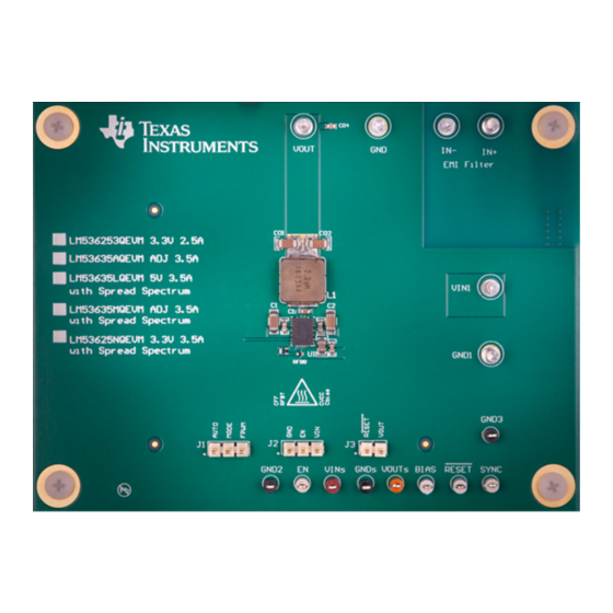
PWM and PFM operation AUTO MODE, along with a low quiescent current, ensures high efficiency at all loads. The Texas Instruments LM53625QEVM and LM53635xQEVM helps to evaluate the operation and performance of the LM53625x and LM53635x and is available for order in five variants. See Table 1 of orderable EVM variants and configuration. -
Page 4: Technical Specification Evm Board
Sense BIAS typical 3.3 V or 5 V BIAS BIAS Voltage Sense If J3 [RESET-VOUT] then VOUTs RESET RESET output external sync frequency source SYNC Switch node SYNC input LM53625xQEVM and LM53635xQEVM User's Guide SNVU526 – May 2016 Submit Documentation Feedback Copyright © 2016, Texas Instruments Incorporated... -
Page 5: Schematics
LM53635NQEVM 3.3V / 3.5A with SS 3.3V fixed AGND Copyright © 2016, Texas Instruments Incorporated Figure 2. Fixed - Output Voltage Option Schematic The fixed voltage option has an internal resistor divider and FB pin that connects directly to Cout capacitor. - Page 6 LM53635NQEVM 3.3V / 3.5A with SS 3.3V fixed AGND Copyright © 2016, Texas Instruments Incorporated Figure 3. Adjustable - Output Voltage Option Schematic Adjustable option uses external resistor divider to define output voltage. The CFF capacitor can be adjusted to make the feedback loop response faster for load transient.
-
Page 7: Board Layout
SNVU526 – May 2016 LM53625xQEVM and LM53635xQEVM User's Guide Submit Documentation Feedback Copyright © 2016, Texas Instruments Incorporated... - Page 8 Figure 5. PCB Layout Top Layer 1 – Top View Figure 6. PCB Layout Mid Layer 2 GND Plane – Top View LM53625xQEVM and LM53635xQEVM User's Guide SNVU526 – May 2016 Submit Documentation Feedback Copyright © 2016, Texas Instruments Incorporated...
- Page 9 Figure 7. PCB Layer Mid Layer 3 – Top View Figure 8. PCB Layer Bottom Layer 4 – Flipped View (as Seen From Bottom of Board) SNVU526 – May 2016 LM53625xQEVM and LM53635xQEVM User's Guide Submit Documentation Feedback Copyright © 2016, Texas Instruments Incorporated...
- Page 10 Board Layout www.ti.com Figure 9. PCB Layer 5 – Dimensions Figure 10. PCB Layer 7 Composite Top LM53625xQEVM and LM53635xQEVM User's Guide SNVU526 – May 2016 Submit Documentation Feedback Copyright © 2016, Texas Instruments Incorporated...
-
Page 11: Operation And Test Setup
NOTE: If the jumper J1 is set to [MODE-FPWM] the part will have a lower efficiency at light loads by maintaining the 2.1-MHz switch frequency. To measure the highest light load efficiency place the Jumper J1 in [AUTO-MODE]. SNVU526 – May 2016 LM53625xQEVM and LM53635xQEVM User's Guide Submit Documentation Feedback Copyright © 2016, Texas Instruments Incorporated... -
Page 12: Measure Load Transient
4.7µF 0.1µF GND1 when laying out the board, keep the EMI fi lter away from Switch Node. Copyright © 2016, Texas Instruments Incorporated Figure 12. 3-Stage EMI Filter Schematic LM53625xQEVM and LM53635xQEVM User's Guide SNVU526 – May 2016 Submit Documentation Feedback... -
Page 13: Posts, Probes, And Jumpers
Rbias = 3 Ω resistor. An external Bias supply voltage can be provided by removing Rbias located on bottom side of PCB to disconnect IC output voltage as source for bias. SNVU526 – May 2016 LM53625xQEVM and LM53635xQEVM User's Guide Submit Documentation Feedback Copyright © 2016, Texas Instruments Incorporated... -
Page 14: Reset And Gnd3 Probe
Test Point, Miniature, Black, TH 5001 Machine Screw, Round, #4-40 × 1/4, Nylon, Philips H1, H2, H3, H4 NY PMS 440 0025 PH panhead LM53625xQEVM and LM53635xQEVM User's Guide SNVU526 – May 2016 Submit Documentation Feedback Copyright © 2016, Texas Instruments Incorporated... - Page 15 LM53635NQEVM Fixed 3.3 V, 3.5 A With Spread Spectrum 2.5/3.5A Synchronous Buck Regulator for Automotive LM53635NQRNLRQ1 Applications, RNL0022A RFBB RFBT 0 Ω RES, 0 Ω, 5%, 0.063 W, 0402 CRCW04020000Z0ED SNVU526 – May 2016 LM53625xQEVM and LM53635xQEVM User's Guide Submit Documentation Feedback Copyright © 2016, Texas Instruments Incorporated...
-
Page 16: Efficiency And Line- And Load-Regulation
= 5 V AUTO = 5 V FPWM Figure 16. LM53635LQEVM Load and Line Regulation Figure 17. LM53635LQEVM Load and Line Regulation LM53625xQEVM and LM53635xQEVM User's Guide SNVU526 – May 2016 Submit Documentation Feedback Copyright © 2016, Texas Instruments Incorporated... -
Page 17: Load Transients
Figure 18. LM53635LQEVM Load Regulation Conducted EMI Figure 20. Conducted EMI Setup - Front View Figure 21. Conducted EMI Setup - Side View SNVU526 – May 2016 LM53625xQEVM and LM53635xQEVM User's Guide Submit Documentation Feedback Copyright © 2016, Texas Instruments Incorporated... - Page 18 Results for 5 Vout With Spread Spectrum. Green-Average EMI Results for 5 Vout With Spread Spectrum. Green- and Yellow-Peak Average and Yellow-Peak LM53625xQEVM and LM53635xQEVM User's Guide SNVU526 – May 2016 Submit Documentation Feedback Copyright © 2016, Texas Instruments Incorporated...
- Page 19 STANDARD TERMS AND CONDITIONS FOR EVALUATION MODULES Delivery: TI delivers TI evaluation boards, kits, or modules, including any accompanying demonstration software, components, or documentation (collectively, an “EVM” or “EVMs”) to the User (“User”) in accordance with the terms and conditions set forth herein. Acceptance of the EVM is expressly subject to the following terms and conditions.
- Page 20 FCC Interference Statement for Class B EVM devices NOTE: This equipment has been tested and found to comply with the limits for a Class B digital device, pursuant to part 15 of the FCC Rules. These limits are designed to provide reasonable protection against harmful interference in a residential installation.
- Page 21 【無線電波を送信する製品の開発キットをお使いになる際の注意事項】 開発キットの中には技術基準適合証明を受けて いないものがあります。 技術適合証明を受けていないもののご使用に際しては、電波法遵守のため、以下のいずれかの 措置を取っていただく必要がありますのでご注意ください。 1. 電波法施行規則第6条第1項第1号に基づく平成18年3月28日総務省告示第173号で定められた電波暗室等の試験設備でご使用 いただく。 2. 実験局の免許を取得後ご使用いただく。 3. 技術基準適合証明を取得後ご使用いただく。 なお、本製品は、上記の「ご使用にあたっての注意」を譲渡先、移転先に通知しない限り、譲渡、移転できないものとします。 上記を遵守頂けない場合は、電波法の罰則が適用される可能性があることをご留意ください。 日本テキサス・イ ンスツルメンツ株式会社 東京都新宿区西新宿6丁目24番1号 西新宿三井ビル 3.3.3 Notice for EVMs for Power Line Communication: Please see http://www.tij.co.jp/lsds/ti_ja/general/eStore/notice_02.page 電力線搬送波通信についての開発キットをお使いになる際の注意事項については、次のところをご覧くださ い。http://www.tij.co.jp/lsds/ti_ja/general/eStore/notice_02.page SPACER EVM Use Restrictions and Warnings: 4.1 EVMS ARE NOT FOR USE IN FUNCTIONAL SAFETY AND/OR SAFETY CRITICAL EVALUATIONS, INCLUDING BUT NOT LIMITED TO EVALUATIONS OF LIFE SUPPORT APPLICATIONS.
- Page 22 Notwithstanding the foregoing, any judgment may be enforced in any United States or foreign court, and TI may seek injunctive relief in any United States or foreign court. Mailing Address: Texas Instruments, Post Office Box 655303, Dallas, Texas 75265 Copyright © 2015, Texas Instruments Incorporated...
- Page 23 IMPORTANT NOTICE Texas Instruments Incorporated and its subsidiaries (TI) reserve the right to make corrections, enhancements, improvements and other changes to its semiconductor products and services per JESD46, latest issue, and to discontinue any product or service per JESD48, latest issue.
Need help?
Do you have a question about the LM53625 QEVM Series and is the answer not in the manual?
Questions and answers