Table of Contents
Advertisement
Quick Links
Advertisement
Table of Contents
Troubleshooting

Related Manuals for ECR International Olsen OLSSV-050


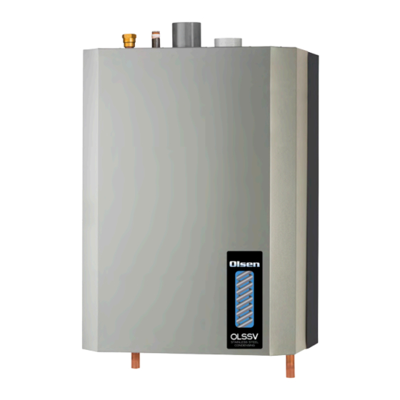
Summary of Contents for ECR International Olsen OLSSV-050
- Page 1 WALL MOUNTED GAS BOILER INSTALLATION, OPERATION & MAINTENANCE MANUAL Models OLSSV OLSSV-075 OLSSV-100 OLSSV-150 OLSSV-200 Manufactured by: ECR International, Inc. 2201 Dwyer Avenue, Utica NY 13501 web site: www.ecrinternational.com P/N# 2400010616, Rev. E [07/2015]...
- Page 2 VERIFY CONTENTS RECEIVED Description Illustration Item Fully Assembled Boiler SIZE SHOWN 050/075/100 Metal Wall Bracket Lag Bolt, 3/8" x 3" Hex (4 ea) *Safety Relief Valve Condensate Trap Height 12.45" [316mm] **Temperature Pressure Gauge Bushing 3/4" x 1/4" 3/4" FNPT Adapter 3/4"...
- Page 3 OVERALL DIMENSIONS Vent Connector Combustion Air Gas Connection(K) Safety Relief Valve Connection (¾ NPT) BACK OF BOILER TOP OF BOILER Wall Hanging Bracket RIGHT SIDE LEFT SIDE FRONT OF BOILER OF BOILER OF BOILER Table 1 : Physical Data Models 050/075/100 150/200 Width (A)
-
Page 4: Table Of Contents
TABLE OF CONTENTS 1 - Introduction ..........................5 2 - Important Safety Information ....................6 3 - Component Listing ........................7 4 - Locating Boiler ......................... 11 5 - Hydronic Piping ........................13 5.2 Special Conditions ......................... 13 5.3 Safety Relief Valve and Air Vent ....................13 5.4 Trim Piping ........................... -
Page 5: Introduction
Check our website frequently for updates: www.ecrinternational.com Information and specifications outlined in this manual in effect at the time of printing of this manual. ECR International reserves the right to discontinue, change specifications or system design at any time without notice and without incurring any obligation, whatsoever. -
Page 6: Important Safety Information
2 - IMPORTANT SAFETY INFORMATION 2.1 General 2.3 Installation shall conform to requirements of authority having jurisdiction or in absence of such Boiler installation shall be completed by qualified agency. requirements: See glossary for additional information. • United States WARNING •... -
Page 7: Component Listing
3 - COMPONENT LISTING 3.1 Component Listing - Refer to diagrams on Supply Water Outlet to Heating System (Out) following pages. Connections supplied for connecting from bottom of boiler. See section 5. Gas Shutoff Valve (Field Installed) Fuel supply isolation during servicing. Factory supplied, Field installed. Temperature Pressure Gauge (Field Installed) See section 7. - Page 8 3 - COMPONENT LISTING FIGURE 3-1 Boiler Components (Viewed from Back of Boiler) NOTE: 050/075/100/150/200 See Section 5-3 SIZE SHOWN For Safety Relief Valve Piping (2) VENT CONNECTOR Instructions (32) GAS CONNECTION (3) COMBUSTION (28) SAFETY RELIEF VALVE AIR INLET (31) WALL MOUNT SUPPORT BRACKET FIGURE 3-2 Jacket Removal (Viewed from Bottom of...
- Page 9 3 - COMPONENT LISTING FIGURE 3-4 Boiler Components 50/75/100 MBH (View from Front of Boiler) As seen on front cover (1) GAS (CONNECTION) NOTE: SHUT OFF VALVE See Section 5 (2) VENT CONNECTOR (28) SAFETY RELIEF For Piping VALVE Instructions (3) COMBUSTION AIR INLET (27) SUPPLY WATER...
- Page 10 3 - COMPONENT LISTING NOTE: FIGURE 3-5 Boiler Components 150-200 MBH (View from Front of Boiler) See Section 5 (1) ) GAS (CONNECTION) For Piping SHUT OFF VALVE (28) SAFETY RELIEF VALVE Instructions (2) VENT CONNECTOR (27) SUPPLY (3) COMBUSTION WATER AIR INLET TEMPERATURE...
-
Page 11: Locating Boiler
4 - LOCATING BOILER 4.1 Boiler Location Considerations FIGURE 4-1 Clearance to Combustible Materials • Ambient room temperature always above 32°F (0°C) to prevent freezing of liquid condensate. • Approved for installation in closets. • Protect gas ignition system components from water (dripping, spraying, rain, etc.) during operation and service (circulator replacement, condensate trap, control FRONT OF BOILER... - Page 12 4 - LOCATING BOILER FIGURE 4-2 Wall Mount Bracket Engaged with Pre-pipe supply and return water connections Bracket on Boiler (50-100 size shown) with factory fittings before wall mounting. 4.3 Wall Mounting Center brackets. Avoid Mount boiler on wall using wall mounting bracket included overhang on sides of with unit.
-
Page 13: Hydronic Piping
5 - HYDRONIC PIPING 5.1 General WARNING • Install piping in accordance with authority having jurisdiction. • Poison hazard. Ethylene glycol is toxic. Do not NOTICE use ethylene glycol. Use two (2) wrenches when tightening boiler's • Never use automotive or standard glycol antifreeze, fitting and pipes. -
Page 14: Trim Piping
5 - HYDRONIC PIPING • Individual boiler discharge piping shall be independent WARNING of other discharge piping. Burn and scald hazard. Safety relief valve could • Size and arrange discharge piping to avoid reducing discharge steam or hot water during operation. safety relief valve relieving capacity below minimum Install discharge piping per these instructions. - Page 15 5 - HYDRONIC PIPING FIGURE 5-4A System Piping - LWCO Probe Location FIGURE 5-4C LWCO Suggested Probe Location Shown 50/75/100 Model Safety Relief Valve Air Vent Safety Relief Valve MINIMUM ACCEPTABLE LWCO HEIGHT FOR LWCO PROBE MINIMUM ACCEPTABLE HEIGHT FOR LWCO PROBE WALL MOUNTED...
- Page 16 5 - HYDRONIC PIPING NOTICE Illustrations are meant to show system piping Piping Legend concept only. Installer is responsible for all equipment and detailing required by authority having jurisdiction. NOTICE Arrange piping to prevent water dripping onto boiler. Primary Loop Equivalent Length Calculation & Pump Selections may be found on pages 84 thru 87 of this manual.
- Page 17 5 - HYDRONIC PIPING FIGURE 5-5 Single Boiler Primary/Secondary Two-Pipe Zoned System With Zone Valves Pump CH/System Pump FIGURE 5-6 Single Boiler Primary/Secondary Two-Pipe Zoned System With Zone Pumps Pump Zone Pump Primary Loop Equivalent Length Calculation & Pump Selections may be found on pages 84 thru 87 of this manual.
- Page 18 5 - HYDRONIC PIPING FIGURE 5-7A Single Boiler Using Primary/Secondary Pumping 12"(305mm) Maximum separation closely spaced tees in primary system loop CH/System Limit length Pump 5' (1.6m) FIGURE 5-7B Single Boiler Using Primary/Secondary Pumping With DHW Tank Heating Load Heating Load 12"(305mm) Maximum separation Closely spaced tees...
- Page 19 5 - HYDRONIC PIPING FIGURE 5-8A Multiple Boiler Primary/Secondary Two Pipe Zoned System With Zone Valves - (See Multiple Boiler Guide) Pump CH/System Pump 12"/305mm Maximum Separation Size common piping System per maximum heat Temperature capacity of entire Sensor system Limit length to 5' (1.6m)
- Page 20 5 - HYDRONIC PIPING FIGURE 5-8B Multiple Boilers Using Primary/Secondary Pumping 12"/305mm Maximum Separation Closely spaced tees in primary system loop CH/System Size common piping Pump per maximum heat System capacity of entire Temperature system Sensor Limit length to 5' (1.6m) Up to 16 boilers P/N# 2400010616, Rev.
- Page 21 5 - HYDRONIC PIPING 5-8C Multiple Boilers Using Primary/Secondary Pumping with DHW Tank 12"/305mm Maximum Separation Closely spaced tees in primary system loop CH/System Pump System Size common piping Temperature per maximum heat Sensor capacity of entire system Limit length to 5' (1.6m) Up to 16 boilers...
-
Page 22: Combustion Air And Vent Piping
6 - COMBUSTION AIR AND VENT PIPING 6.1 General • Any improper operation of common venting system should be corrected so installation conforms with National This boiler requires a dedicated vent system. Install Fuel Code, ANSI Z223.1/NFPA 54 and/or Natural Gas combustion air and vent piping in accordance with these and Propane Installation Code, CAN/CSA B149.1. -
Page 23: Vent Pipe Installation
6 - COMBUSTION AIR AND VENT PIPING 6.4 Vent Pipe Installation • Canadian installations only. All venting material, primer and glue must be listed to ULC S636. • Minimum and maximum combustion air and vent pipe lengths listed in Table 5. Pipe length counted from •... -
Page 24: Venting Configurations
6 - COMBUSTION AIR AND VENT PIPING 6.6 Venting Configurations NOTICE Various venting configurations can be applied to this boiler. Use of vent covers may cause freezing. If using For guidance see Venting Configuration Table 7A and vent covers overall vent length must be considered. corresponding figures. - Page 25 6 - COMBUSTION AIR AND VENT PIPING FIGURE 6-1 Two Pipe Roof Vent 12" (205mm) Min. horizontal 12" (205mm) Min. separation between combustion air intake and vent of same appliance. 12" (305mm) Min. 15" 12" (205mm) Min. or greater separation (381mm) ...
- Page 26 6 - COMBUSTION AIR AND VENT PIPING FIGURE 6-4 Side Wall Concentric Terminal FIGURE 6-5 Side Wall Concentric Terminal Multiple Appliances Roof 1"(2.54cm) Overhang 1" (25mm) Maximum 1" (25.4mm) Maximum Maximum 12" (305mm) Minimum * See Note 36"(0.9m(914mm) Below (28m)) Minimum Vent Maintain 12"...
- Page 27 6 - COMBUSTION AIR AND VENT PIPING FIGURE 6-7 Concentric Roof Terminal Vent Glue inner vent pipe to prevent Maintain 12"(305mm) US (18"(457mm) Canada) recirculation. minimum clearance above Maintain 12" (305mm) US highest anticipated snow (18"(457mm) Canada) minimum Combustion Air level 24"...
- Page 28 6 - COMBUSTION AIR AND VENT PIPING FIGURE 6-10 Flue on Sidewall, Combustion Air on Roof FIGURE 6-12 Two Pipe Side Wall with 45° Vent Maintain 12"(305mm) US (18"(457mm) Canada) minimum clearance Combustion above highest anticipated 12" (205mm) Min. Vent snow level 24"...
-
Page 29: Side Venting Terminal Requirements
6 - COMBUSTION AIR AND VENT PIPING 6.7 Side Venting Terminal Requirements • USA - National Fuel Gas Code, ANSI 223.1/NFPA 54. • Canada - Natural Gas and Propane Installation Code, CAN/CSA B149.1 See figure 6-15 Venting terminal from doors and windows See figure 6-16 Venting terminal from forced air inlet of other appliances See figure 6-17... - Page 30 6 - COMBUSTION AIR AND VENT PIPING FIGURE 6-18 Keep vent termination 3’ minimum Vegetation, (0.9m) away from vegetation. Position Plants & termination where vent vapors will not Shrubs damage plants/shrubs or air conditioning equipment. Termination Vent termination US only - 4’ (1.2m), Meters, Canada - 6' (1.9m) horizontally from, Regulators,...
-
Page 31: Multiple Boiler Venting Installation
6 - COMBUSTION AIR AND VENT PIPING 6.8 Multiple Boiler Venting Installation FIGURE 6-20 Condensate Drain • Multiple boiler application boiler shall be vented individually. • Follow guidelines as described in figures 6-1 through 6-14. 6.9 Condensate Piping • Use materials acceptable to authority having jurisdiction. In absence of such authority: End must be •... -
Page 32: Gas Supply Piping
7 - GAS SUPPLY PIPING FIGURE 7-1A Gas Connection (at top of Boiler) CAUTION 50/75/100 Shown WHAT TO DO IF YOU SMELL GAS • Do not try to light any appliance. Attach Supplied Gas Shutoff Valve (shown Connection • Do not touch any electrical switch; do not use in open position) any phone in your building. - Page 33 7 - GAS SUPPLY PIPING FIGURE 7-2 Manual Gas Shutoff Valve - Outside DANGER Boiler Jacket (view from top rear of boiler) Fire Hazard. Do not use matches, candles, open Shown 50/75/100 Model flames, or other methods providing ignition source. Failure to comply will result in death or serious injury.
-
Page 34: Electrical Connections
8 - ELECTRICAL CONNECTIONS 8.1 General WARNING Electrically bond boiler to ground in accordance with Electrical shock hazard. Turn OFF electrical power requirements of authority having jurisdiction. Refer to: supply at service panel before making electrical • USA- National Electrical Code, ANSI/NFPA 70. connections. - Page 35 8 - ELECTRICAL CONNECTIONS • Argus Link (Multiple boiler applications only) NOTICE • Outdoor Sensor, if used. Use dry contact for wires to CH T-T terminal and A. Provided with boiler. DHW T-T terminal. E33 error code is displayed if B.
-
Page 36: Start Up Procedure
9 - START UP PROCEDURE 9.1 Fill Boiler With Water And Purge Air NOTICE NOTICE IMPORTANT: Condensate trap must be manually filled with water at initial start up. To maintain boiler efficiency and prevent boiling inside the heat exchanger, flush entire heating FIGURE 9-1 Condensate Drain Assembly system until clean. - Page 37 9 - START UP PROCEDURE 9.3 Program Boiler Control FIGURE 9 -2 User Interface Description - Manual Lockout Reset - Enter/Exit user menu - Go to previous screen - Select a menu item - Confirm new parameter value - Scroll up to next menu item - Increase value - Scroll down to next menu item - Decrease value...
- Page 38 9 - START UP PROCEDURE 9.4 Boiler Start-up and Operational Test For Propane (LP): Verify air is purged from hydronic piping 9160 x cu ft Input (MBH) System test pumps - verify each pump is seconds operational For Metric formulas- See Glossary Verify gas piping •...
- Page 39 9 - START UP PROCEDURE FIGURE 9-3 Gas Valve - Models WARNING 050/075/100/150/200 MBH Fire, explosion, asphyxiation and electrical shock hazard. Read this instruction and understand all requirements, including requirements of authority Throttle Screw having jurisdiction before making adjustments. Failure to follow these instructions could result in death or serious injury.
-
Page 40: Perform Csd-1 Compliance Test
9 - START UP PROCEDURE See Figure 9-4 for location of Offset Screw on FIGURE 9-4 Offset Screw Location - Models modulating gas valve of various boiler models. T40 050/075/100/150/200 MBH male Torx bit is necessary for removal of Offset Screw cap and adjustment of Offset Screw. -
Page 41: Complete Start Up Procedure
9 - START UP PROCEDURE 9.7 Complete Start Up Procedure WARNING Reset control parameters to operating settings if Asphyxiation hazard. Carbon monoxide is odorless, adjusted to allow startup and operation test. tasteless, clear colorless gas, which is highly toxic. Follow instructions TO TURN OFF GAS TO APPLIANCE Verify cap is firmly placed on combustion analyzer (page 42) if boiler is not being placed into port to prevent CO emission. -
Page 42: Operating Instructions
10 - OPERATING INSTRUCTIONS FOR YOUR SAFETY READ BEFORE OPERATING CAUTION WARNING WHAT TO DO IF YOU SMELL GAS If you do not follow these instructions • Do not try to light any appliance. exactly, a fire or explosion may result •... -
Page 43: General Maintenance And Cleaning
11 - GENERAL MAINTENANCE AND CLEANING 11.1 Beginning of Each Heating Season DANGER • Check boiler area is free from combustible materials, Before servicing, turn off electrical power to boiler gasoline, and other flammable vapors and liquids. at service switch. Close manual gas valve to turn •... - Page 44 11 - GENERAL MAINTENANCE AND CLEANING Figure 11-2 Condensate Trap 11.2 Annual Shut Down Procedure • Follow instructions “To Turn Off Gas To Appliance” unless boiler is also used to supply domestic hot water. See section 10. • Drain system completely if system does not have antifreeze when heating system is to remain out of service during freezing weather.
-
Page 45: Ratings And Capacities
12 - RATINGS AND CAPACITIES Table 13 - Sea Level Ratings SEA LEVEL RATINGS NATURAL AND PROPANE GASES Boiler Input Rate Heating Net AHRI (MBH) Size Capacity Rating, Water AFUE (MBH) (MBH) (1)(2) (1)(3) Maximum Minimum 95.0 95.0 95.0 95.0 95.0 1000 Btu/hr (British Thermal Units Per Hour) Heating Capacity and AFUE (Annual Fuel Utilization Efficiency) are based on DOE (Department of Energy) test... -
Page 46: Trouble Shooting
13 - TROUBLE SHOOTING If boiler does not function. Remove Jacket. Is User Interface lit? Check for 120 vac in boiler high Does display show "Standby - No voltage terminal box. Demand? Is 120 vac present? Locate fuse holder on front of Check power supply to There is no call for control and pull to check fuse. - Page 47 13 - TROUBLE SHOOTING Go to Page For Screen Display Explanation Troubleshooting Control has blocking error for more than 20 Go to Page 49 hours in a row. Three unsuccessful ignition attempts in a row Go to Page 50 Open gas valve power circuit. May involve high temperature switch, gas valve, or gas Go to Page 49 valve relay in control module.
- Page 48 13 - TROUBLE SHOOTING Go to Page For Screen Display Explanation Troubleshooting Low water cutoff sees no water. Go to Page 55 Flue temperature sensor sees temperature Go to Page 56 higher than 200°F. E 39 B l o c k i n g E r r o r F l u e G a s E r r o r Return water temperature sensor sees Go to Page 57...
- Page 49 13 - TROUBLE SHOOTING P/N# 2400010616, Rev. E [07/2015]...
- Page 50 13 - TROUBLE SHOOTING P/N# 2400010616, Rev. E [07/2015]...
- Page 51 13 - TROUBLE SHOOTING P/N# 2400010616, Rev. E [07/2015]...
- Page 52 13 - TROUBLE SHOOTING P/N# 2400010616, Rev. E [07/2015]...
- Page 53 13 - TROUBLE SHOOTING P/N# 2400010616, Rev. E [07/2015]...
- Page 54 13 - TROUBLE SHOOTING P/N# 2400010616, Rev. E [07/2015]...
- Page 55 13 - TROUBLE SHOOTING P/N# 2400010616, Rev. E [07/2015]...
- Page 56 13 - TROUBLE SHOOTING P/N# 2400010616, Rev. E [07/2015]...
- Page 57 13 - TROUBLE SHOOTING P/N# 2400010616, Rev. E [07/2015]...
- Page 58 13 - TROUBLE SHOOTING P/N# 2400010616, Rev. E [07/2015]...
- Page 59 13 - TROUBLE SHOOTING P/N# 2400010616, Rev. E [07/2015]...
- Page 60 13 - TROUBLE SHOOTING P/N# 2400010616, Rev. E [07/2015]...
- Page 61 13 - TROUBLE SHOOTING P/N# 2400010616, Rev. E [07/2015]...
- Page 62 13 - TROUBLE SHOOTING P/N# 2400010616, Rev. E [07/2015]...
-
Page 63: Trouble Shooting (Temperature Resistance Chart)
13 - TROUBLE SHOOTING Thermistor Resistance Chart Temperature Temperature Resistance °C °F 36100 28590 22790 18290 14770 12000 9805 8055 6653 5524 4809 3863 3253 2752 2337 1994 1707 1467 1265 1095 P/N# 2400010616, Rev. E [07/2015]... -
Page 64: Wiring Diagram
14 - WIRING DIAGRAM 14.1 Connection Diagram - 050/075/100 MBH P/N# 2400010616, Rev. E [07/2015]... - Page 65 14 - WIRING DIAGRAM 14.2 Schematic Diagram of Ladder Form - 050/075/100 MBH P/N# 2400010616, Rev. E [07/2015]...
- Page 66 14 - WIRING DIAGRAM 14.3 Connection Diagram - 150/200 MBH P/N# 2400010616, Rev. E [07/2015]...
- Page 67 14 - WIRING DIAGRAM 14.4 Schematic Diagram of Ladder Form - 150/200 MBH P/N# 2400010616, Rev. E [07/2015]...
-
Page 68: Glossary
15 - GLOSSARY • ANSI - American National Standards Institute, Inc. • GAS PIPE SIZES - Table 14 oversees creation and maintenance of voluntary consensus standards, including ANSI Z21.13/CSA 4.9: NATURAL GAS Gas-Fired Low Pressure Steam and Hot Water Boilers. Pipe Capacity - BTU Per Hour Input Includes Fittings Length of Pipe - Ft. - Page 69 15 - GLOSSARY • QUALIFIED AGENCY - Any individual, firm, corporation, or company engaged in and responsible for: • Installation, testing, or replacement of gas piping, or connection, installation, testing, repair or servicing of appliances and equipment. • Experienced in such work. •...
-
Page 70: Appendix A - Control Module
APPENDIX A - CONTROL MODULE 1.1 Introduction Operation with LCD character display module Boiler is equipped with programmable electronic control and user interface module. 1.2 Operation • Display: 4 x 20 character LCD screen to show boiler status. • Function Keys Description - Manual Lockout Reset - Enter/Exit user menu... -
Page 71: Sequence Of Operation
APPENDIX A - CONTROL MODULE 1.4 Sequence of Operation Operational State User Interface Display Explanation Boiler operates in standby mode until demand for Central Heat (CH) Heat or Domestic Hot Water (DHW) is Demand? detected. CH or DHW pump is turned on based DHW CH on type of heating demand. - Page 72 APPENDIX A - CONTROL MODULE 1.4 Sequence of Operation Operational State User Interface Display Explanation After 2 seconds If flame detected before Gas Valve opens during ignition boiler will lockout. Lockout Flame Error A21 Detected? Please refer to troubleshooting guide. Note: 5 Ignition trials,...
-
Page 73: User Menu
APPENDIX A - CONTROL MODULE 1.5 User Menu Explanation User Interface Display Boiler operates in standby mode until demand for Central Heat (CH) or Domestic Hot Water (DHW) is detected. User Menu (Press Menu button on user interface to access User Menu) User Menu structure includes: •... - Page 74 APPENDIX A - CONTROL MODULE Explanation User Interface Display Adjust CH set point to hydronic system design while in Operating in CH Mode = 0 (CH with Thermostat) or 3 (Permanent Demand). In CH Mode = 1 (CH with Thermostat and Outdoor Reset) or 2 (CH with Full Outdoor Reset).
- Page 75 APPENDIX A - CONTROL MODULE Explanation User Interface Display Installer Menu Installer Menu structure includes: • User 'Menu' can be accessed by pressing 'Menu' key on user interface. • Installer 'Menu' can be accessed by first pressing and holding the 'Enter' key continue to hold and at the same time press and hold the 'Menu’...
- Page 76 APPENDIX A - CONTROL MODULE Explanation User Interface Display Installer Menu Control module logs successful and failed ignition attempts. Information accessed in ‘Ignition Attempts’ Screen as shown. Ignition attempts are stored in non-volatile memory and are retained in event of power failure. Figure A-1 Typical Ignition Cycle Following control features are implemented to ensure safe and reliable operation of Combustion System:...
- Page 77 APPENDIX A - CONTROL MODULE Explanation User Interface Display Boiler stores information regarding total CH and DHW run time in hours. Data stored in non-volatile memory and retained in event of power failure. Boiler logs last 16 blocking errors and 16 lockout errors in non-volatile memory.
- Page 78 APPENDIX A - CONTROL MODULE Explanation User Interface Display Two pump modes are available: Pump Mode = 0 ‘CH or CH&DHW’ • In this mode either CH or DHW pump terminal is energized depending on type of demand (CH or DHW). •...
- Page 79 APPENDIX A - CONTROL MODULE Explanation User Interface Display 4. Central Heating (CH) modes available: • CH Mode = 0 ‘CH with Thermostat’ • Boiler will attempt to satisfy CH demand while CH thermostat input is closed. • Boiler will modulate its firing rate to maintain CH set point and match system heat load.
- Page 80 APPENDIX A - CONTROL MODULE Explanation User Interface Display If outdoor temperature is greater than Warm Weather Shutdown Temperature, demand for CH blocked and pumps stopped. Allowed Range: 35°F to 100°F (2°C to 38°C) Default Setting: 70°F (21°C) Boiler capable of operating in Outdoor Reset Mode when included Outdoor Sensor is connected and proper CH Mode selected.
- Page 81 APPENDIX A - CONTROL MODULE Explanation User Interface Display Outdoor reset boost function increases CH set point by increment (‘Temp’) if CH demand continues beyond pre-set time limit (‘Time’). CH set point will continue to increase until set point reaches 195°F / 91°C Allowable Temperature Increment: 0..36 °F (0..20 °C) Default Temperature increment:...
- Page 82 APPENDIX A - CONTROL MODULE Explanation User Interface Display Maximum time boiler operates in DHW mode limited by DHW Maximum Priority Time Setting. Priority timer starts when both CH and DHW demand is present. Boiler will switch from DHW back to CH operation after Maximum Priority Time has elapsed.
-
Page 83: Optional User Interface Relocation
OPTIONAL USER INTERFACE RELOCATION User interface can be easily relocated outside of the boiler. Figure - A User Interface Terminal Block Follow instructions TO TURN OFF GAS TO APPLIANCE found on page 42. Verify all electrical power to boiler is turned off. -
Page 84: Primary Loop Equivalent Length Calculations & Pump Selection
50/75/100 MBH - PRIMARY LOOP EQUIVALENT LENGTH CALCULATION & PUMP SELECTION For 50/75/100 MBH Boilers (This boiler must be piped with a primary loop) These charts are valid for piping diagrams on pages 17 & 18 Instructions: Pipe diameter determines pump size. Smaller the diameter of pipe, larger the pump. 50/75/100 Mbh boilers can be piped in 3/4"... - Page 85 50/75/100 MBH - PRIMARY LOOP EQUIVALENT LENGTH CALCULATION & PUMP SELECTION Chart 3 Equivalent Length Enter Number of Pipe Diameter Fitting Multiply By Fittings A x B 90° Elbow 1.875 45° Elbow 1¼" Tee-branch 3.75 (Any pipe/fitting larger than 1¼", Tee-through 1.25 count as 1¼")
- Page 86 150/200 MBH - PRIMARY LOOP EQUIVALENT LENGTH CALCULATION & PUMP SELECTION For 150/200 MBH Boilers (This boiler must be piped with a primary loop) These charts are valid for piping diagrams on pages 17 & 18 Instructions: Pipe diameter determines pump size. Smaller the diameter of pipe, larger the pump. 150/200 Mbh boilers can be piped in 3/4"...
- Page 87 150/200 MBH - PRIMARY LOOP EQUIVALENT LENGTH CALCULATION & PUMP SELECTION Chart 3 Equivalent Length Enter Number of Pipe Diameter Fitting Multiply By Fittings A x B 90° Elbow 45° Elbow 1½" Tee-branch (Any pipe/fitting larger than 1½", Tee-through count as 1½") Swing check valve 12.5 Lift check valve...
- Page 88 IMPORTANT In accordance with Section 325 (f) (3) of the Energy Policy and Conservation Act, this boiler is equipped with a feature that saves energy by reducing the boiler water temperature as the heating load decreases. This feature is equipped with an override which is provided primarily to permit the use of an external energy management system that serves the same function.
Need help?
Do you have a question about the Olsen OLSSV-050 and is the answer not in the manual?
Questions and answers