Table of Contents
Advertisement
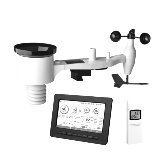
PROFESSIONAL WIFI WEATHER STATION
Operation Manual
Model: HP2551
Thank you for purchasing this Professional WIFI Weather Station! This
device provides accurate weather readings and is Wi-Fi capable to stream
data from the weather station to Internet based weather services.
This manual will guide you, step-by-step, through setting up your weather
station and console, and understanding the operation of your weather station.
Use this manual to become familiar with your professional weather station
and save it for future reference.
1
Advertisement
Table of Contents

Related Manuals for ECOWITT HP2551CA


Summary of Contents for ECOWITT HP2551CA
- Page 1 PROFESSIONAL WIFI WEATHER STATION Operation Manual Model: HP2551 Thank you for purchasing this Professional WIFI Weather Station! This device provides accurate weather readings and is Wi-Fi capable to stream data from the weather station to Internet based weather services. This manual will guide you, step-by-step, through setting up your weather station and console, and understanding the operation of your weather station.
-
Page 2: Table Of Contents
1 Table of Contents 1 TABLE OF CONTENTS..................2 2 WARNINGS AND CAUTIONS................4 3 UNPACKING......................4 4 OVERVIEW......................6 4.1 D .....................6 ISPLAY CONSOLE 4.2 I :....................6 NDOOR SENSOR 4.3 O :.................... 7 UTDOOR SENSOR 4.4 O ................... 7 PTIONAL SENSORS 5 SET UP GUIDE.................... - Page 3 5.10.4 Temperature unit setting................ 37 5.10.5 Barometric unit..................37 5.10.6 Wind speed unit..................37 5.10.7 Rainfall unit................... 37 5.10.8 Solar Rad. Unit..................38 5.10.9 Multi Channel Sensor................38 5.10.10 Backlight setting.................. 39 5.10.11 Longitude: Latitude setting..............41 5.10.12 Reset Weekly Rain................41 5.10.13 Rainfall season (default: January)............
-
Page 4: Warnings And Cautions
2 Warnings and Cautions Warning: Any metal object may attract a lightning strike, including your weather station mounting pole. Never install the weather station in a storm. Warning: If you are mounting the weather station to a house or structure, consult a licensed electrician for proper grounding. A direct lightning strike to a metal pole can damage or destroy your home. - Page 5 If components are missing from the package, or broken, please contact customer service to resolve the issue. Note: Batteries for the outdoor sensor package are not included. You will need 2 AA size batteries, alkaline or Lithium batteries (Lithium recommended for colder climates). Note: The console operates using an AC adapter.
-
Page 6: Overview
4 Overview 4.1 Display console memory card slot USB port Power jack Reset Figure 1: Display console Note: The USB port in the console of weather station is only for firmware update, not for data communication (USB cable not included). You can use a SD card for the firmware update.(SD card not included). -
Page 7: Outdoor Sensor
4.3 Outdoor sensor: Figure 3: Sensor assembly components 1. Wind speed cups 7. Antenna 2. Wind vane 8. U-Bolts 3. Thermo- and hygro-meter senor 9. Battery compartment door 4. Rain collector 10. Reset button 5. Bubble level 11. LED (red) to indicate data transmission 6.Solar panel 12. - Page 8 Sensor Image Maximum Number WH31 Multi-channel temperature and humidity sensor WH51 Soil moisture sensor WH41 outdoor PM2.5 air quality sensor WH43 indoor PM2.5 air quality sensor WH41 and WH43 share the channels WH55 Water leak alarm WH57 Thunder and lightning WH45 Indoor PM2.5/PM10 CO2 air quality sensor WN34S Stainless-steel probe thermometer...
- Page 9 Note: For above optional sensors: 1. Console display just show the current data, the history data save in the SD card. 2. Ecowitt.net can support these sensor data upload. WU website doesn’t support extra sensor.
-
Page 10: Set Up Guide
5 Set up Guide 5.1 Pre Installation Checkout To complete assembly you will need a Philips screwdriver (size PH0) and a wrench (size M5; included in package). Before installing the weather station on the place of operation, we recommend placing the weather station at a temporary location with easy access for one week. -
Page 11: Outdoor Sensor Package Assembly
and the mounting pole is 6’ or 1.83m tall, install the sensor array 4 x (20 – 6)’ = 56’ or 4 x (6.1-1.83)=17.08m away. 3. Installing the weather station over sprinkler systems or other unnatural vegetation may affect temperature and humidity readings. We suggest mounting the sensor array over natural vegetation. -
Page 12: Install Wind Vane
5.3.2 Install wind vane Push the wind vane onto the shaft on the top side of the sensor package, until it goes no further, tighten the set screw, with a Philips screwdriver (size PH0). Make sure the wind vane can rotate freely. The wind vane’s movement has a small amount of friction, which is helpful in providing steady wind direction measurements. -
Page 13: Install The Rain Gauge Funnel
Figure 6: Wind speed cup installation diagram 5.3.4 Install the Rain Gauge Funnel Rotate clockwise to attach the funnel to the sensor array. Figure 7: Rain Gauge Funnel installation diagram 5.3.5 Install Batteries in sensor package Open the battery compartment and insert 2 AA batteries in the battery compartment. -
Page 14: Mount Assembled Outdoor Sensor Package
Figure 8: Battery installation diagram Note: If LED does not light up or is on permanently, make sure the battery is inserted the correct way and inserted fully, starting over if necessary. Do not install the batteries backwards as it may permanently damage the outdoor sensor. -
Page 15: Reset Button And Transmitter Led
Figure 9: Sensor package mounting diagram .Note: If you tested the full assembly indoors and then came back here for instructions and mounted to sensor package outdoor you may want to make some further adjustments on the console. The transportation from indoor to outdoor and handling of the sensor is likely to have “tripped”... -
Page 16: Indoor Sensor Set Up
Figure 10: Reset button and Transmitter LED location 5.4 Indoor Sensor Set Up Note: To avoid permanent damage, please take note of the battery polarity before inserting the batteries. Remove the battery door on the back of the sensor. Insert two AA batteries. Figure 11: Indoor sensor battery installation 5.5 Multi-channel temperature and humidity sensor (Optional) The device supports up to 8 additional thermo-hygrometer sensors (WH31),... -
Page 17: Install Batteries
5.5.1 Install batteries 1. Remove the battery door on the back of the transmitter(s) by sliding down the battery door, as shown in Figure 12 . Figure 12: Battery installation for Multi-channel sensor 2. BEFORE inserting the batteries, locate the dip switches on the inside cover of the lid of the transmitter. - Page 18 Figure 13: Dip Switch diagram 5. Insert two AA batteries. 6. Verify the correct channel number (CH) and temperature units of measure (°F vs. °C) are on the display, as shown in Figure 14. (1) Temperature (2) Temperature units (°F vs. °C) (3) Channel number (4) Relative humidity Figure 14: sensor LCD display...
-
Page 19: Sensor Placement
5.5.2 Sensor Placement The best mounting location for the indoor sensor is in a location that never receives direct sunlight, not even through windows. Also, do not install in a location where a nearby radiant heat source (radiator, heaters, etc.) will affect it. -
Page 20: Best Practices For Wireless Communication
5.6 Best Practices for Wireless Communication Wireless (RF) communication is susceptible to interference, distance, walls and metal barriers. We recommend the following best practices for trouble free wireless communication between both sensor packages and the console: Indoor sensor placement: The sensor will have the longest reach for its ... -
Page 21: Console Display
Medium RF Signal Strength Reduction Glass (untreated) 5-15% Plastics 10-15% Wood 10-40% Brick 10-40% Concrete 40-80% Metal 90-100% Table: RF Signal Strength reduction 5.7 Console Display See 6 to help you identify elements of the console’s display screen. Figure 16: Display Console Screen Layout... - Page 22 Description Description Outdoor temperature Last lightning strikes detected time / distance; daily counts (optional sensor) Outdoor Feels Like/Dew Indoor humidity point/Humidity/10Min. Average Wind Direction/Max Daily Gust PM2.5 concentration(optional RF signal bar for multi-channel sensor) temperature and humidity sensor(optional sensor) RF signal bar for PM2.5 Multi-channel temperature and sensor(optional sensor) humidity sensor cycle display...
-
Page 23: Initial Display Console Set Up
5.7.1 Initial Display Console Set Up Immediately after power up (inserting power adapter), the unit will turn on the display, and the unit will start to look for reception of the indoor and outdoor sensor data. This may take up to 3 minutes. Dark Background Display Light Background Display Note: Sunrise/sunset time display will only work properly when GEO... -
Page 24: Key Functions
5.7.2 Key functions Figure 17: Buttons around the display There is a set of eight keys on the bottom of the display console. The following table briefly explains the function of these keys. Icon Description Brightness control key Press this key to decrease the brightness Brightness control key Press this key to enhance the brightness Backlight on/off key... -
Page 25: Main Interface Icons Explain
5.7.3 Main interface icons explain 5.7.3.1 Temperature Icon Temperature Range Color Ring Temperature Range Color Ring (degF) (degF) < -10 50-60 -10 to 0 60-70 0 to 10 70-80 10-20 80-90 20-30 90-100 30-40 100-110 40-50 > 110... - Page 26 5.7.3.2 Humidity Icon Humidity Range Color Ring Humidity Range Color Ring 0%, No signal or 50 to 60 dashes 1 to 10 60 to 70 10 to 20 70 to 80 20 to 30 80 to 90 30 to 40 90 to 99 40 to 50 100%...
-
Page 27: Multiple Channel Selection And Scroll Mode
5.7.3.4 Hourly Rainfall Icon Hourly Rain (in) Icon Hourly Rain (in) Color Ring 0.6 to 0.8 0 to 0.2 0.8 to 1 0.2 to 0.4 1 to 1.2 0.4 to 0.6 1.2 to 1.4 5.8 Multiple Channel Selection and Scroll Mode Multi-channel sensor is an optional sensor, not included in the package. - Page 28 Figure 18: Max/Min Screen Icon Description Selection key Press this key to select the weather MAX/MIN record which need to clear Selection key Press this key to select the weather MAX/MIN record which need to clear Enter key While the desired weather MAX/MIN record selected , press this key to popup Message Box ”Clear the Max/Min record?”.
-
Page 29: History Record Mode
History key Press this key to select History data display. Return key Press this key to return to normal display mode 5.9.2 History Record Mode While in normal display, press the key twice to enter History Record Mode. Figure 19: History record Screen Icon Description File Select key... - Page 30 Scroll right key Press this key to view the right of the scrollable area. Page up key Press this key to scroll up the page you are viewing Page down key Press this key to scroll down the page you are viewing History key Press this key to select the Max/Min record or History.
- Page 31 5.9.2.2 View a specific page of history While in History Record Mode, press the key to enter the page selection mode: Figure 21: view a specific page of history Screen Press to select a digit in a number, press to change the number. Press to change the activated option field, toggle OK or Cancel then press key to confirm.
-
Page 32: View Graph
5.9.3 View Graph While in History Record Mode, press the key three times to enter Graph Mode. Figure 22: Graph Screen Press to shift the data display of 12/24/48/72H. Press to view the graph of the following data: Indoor outdoor temperature Dew Point and Feels like ... -
Page 33: View Channel Data
5.9.4 View Channel Data While in normal display, press the key four times to enter Channel Data Mode. If you purchase the optional sensor, soil moisture sensor or PM2.5 sensor or multi-channel temperature and humidity sensor, their data can be showed on Channel Data screen. -
Page 34: Setting Mode
5.10 Setting Mode While in normal display, press the key to enter Setting Mode. You can select the below sub-mode by pressing the Figure 24: Setup Menu Screen Icon Description Select key Press this key to select the unit or scrolls the value Select key Press this key to select the unit or scrolls the value. -
Page 35: Date And Time Setting
Down arrow key Press this key to change the activated option field Set key Press this key to select the Setting sub-Mode Return key Press this key to return to previous mode 5.10.1 Date and Time setting While in Menu Setting Mode, press key to select Date and Time Setup field, press key to enter Date and Time Setup mode:... - Page 36 the minute, the minute digit will turn red, press the key to change the minute setting. Press to set the second, and the second digit will turn red, press the key to change the second setting Date setting Press key to select Date setting field, the day digit on focus turns red, press the key to change the day setting.
-
Page 37: Time Format Setting
synchronize with time server immediately. Console time will be updated at 2:01am automatically when internet access is possible. 5.10.2 Time Format setting Press to change the time format between hour: minute: second (h:mm:ss), hour: minute: second AM (h:mm:ss AM) and AM hour: minute: second (AM h:mm:ss). -
Page 38: Solar Rad. Unit
5.10.8 Solar Rad. Unit Press to change the solar radiation units of measure between W/m^2, lux and fc. 5.10.9 Multi Channel Sensor In Multi channel sensor Setup Screen, you can rename the Multi-channel temperature and humidity sensor or register the Multi-channel temperature and humidity sensor again while the sensor lost connection to console display. -
Page 39: Backlight Setting
Figure 27: rename the sensor Screen Press key to select Register setting field, press the key to register the selected sensor 5.10.10 Backlight setting While in Menu Setting Mode, press key to select Backlight Setup field, press key to enter backlight Setup mode:... - Page 40 Figure 28: Backlight Setting Screen Automatic control backlight: select this option, the backlight will auto turn on and off according the set time Turn on the backlight: set the time of turning on backlight Turn off the backlight: set the time of turning off backlight Automatic brightness adjustment: select this option, the brightness will change according to the light intensity measured from outdoor sensor Maximum brightness: set the maximum brightness while it is the highest...
-
Page 41: Longitude: Latitude Setting
5.10.11 Longitude: Latitude setting While in Menu Setting Mode, press key to select Longitude: Latitude Setup field, press key to enter Longitude Latitude Setup mode: Figure 29: Longitude and Latitude Setting Screen The sunrise/sunset times will be calculating automatically base on the Longitude and Latitude. -
Page 42: Rainfall Season (Default: January)
Your console is capable of sending your sensor data to select internet-based weather services. The supported services are shown in the table below: Service Website Description Ecowitt https://www.ecowitt.net Ecowitt is a new weather Weather server that can host a bunch of sensors that other services don’t support. Weather https://www.wunderground. -
Page 43: Wunderground Server Setup
Website customized website, if the website has the same protocol with Wunderground or Ecowitt Table: Supported weather services Note: If you are testing the setup with the outdoor sensor package nearby and indoor, you may want to consider connecting to Wi-Fi, but not yet configuring any of the weather services. - Page 44 Select More | Register Your PWS (3) Click Send Validation Email (4). Respond to the validation email from Wunderground.com (it may take a few minutes). Select More | Register Your PWS (5) again. This time you will be asked details about your weather station. Go ahead and fill out the form After completing the weather station, you will see something like this: Your station ID will have the form: KSSCCCC###, where K is for USA station (I for international), SS is your state, CCCC is an abbreviation for...
- Page 45 Take note of the station ID and key/password and enter it in the Weather Server: 2) Registration on console display Press key to enter Weather Server set up mode. The device can be configured to send real-time data to wunderground.com®. Enter the Station ID and Password obtained from Wunderground.com.
- Page 46 Set Station ID: Press to highlight the Station ID. Enter your station ID. Press to display the keyboard. Press to scroll to the character and press to select the character. Press to return to the setup page. Set Station Key: Press to highlight the station key.
- Page 47 http://www.wunderground.com/personal-weather-station/dashboard?ID=ST ATIONID It will show a page such as this, where you can look at today’s data and historical data as well: There are also some very useful mobile apps. The URLs provided here go to the Web version of the application pages. You can also find them directly from the iOS or Google Play stores: WunderStation: iPad application for viewing your station’s data and ...
- Page 48 WU Storm: iPad and iPhone application for viewing radar images, animated wind, cloud coverage and detailed forecast, and PWS station data https://itunes.apple.com/us/app/wu-storm/id955957721...
- Page 49 Weather Underground: Forecast: iOS and Android application for forecasts https://itunes.apple.com/us/app/weather-underground-forecast/id486154808 https://play.google.com/store/apps/details?id=com.wunderground.android.w eather&hl=en PWS Weather Station Monitor: View weather conditions in your neighborhood, or even right in your own backyard. Connects to wunderground.com https://itunes.apple.com/us/app/pws-weather-station-monitor/id7137059...
-
Page 50: Weathercloud Server Setup
5.10.15.2 Weathercloud server setup To register with Weathercloud follow these steps: Visit weathercloud.net and enter a Username, Email and Password to sign up. Respond to the validation email from Weathercloud (it may take a few minutes). - Page 51 You will then be prompted to add a device/ Select “Create device” and enter your station’s information: After registering your station, take note of the “Weathercloud ID” and “Key” presented to you. Enter these values in the Weather Server: Figure 31: Weathercloud Server setup screen scroll value scroll value Scroll field...
- Page 52 Weather Observations Website (WOW) server setup 5.10.15.3 To have your weather station upload data to the Met Office’s WOW site you will need to complete the following steps: Sign Up with WOW Navigate your browser to http://wow.metoffice.gov.uk. On the top-right side of the resulting page you will see menu options.
- Page 53 The actual form is longer, but all questions should be self-explanatory. Complete and submit the form. You will receive the following notice on completion: Confirm your email with WOW Respond to the validation email from WOW(it may take a few minutes). Login to WOW Follow instructions on the screen and login to the site.
- Page 54 You will be presented with a form where you detail your station’s location and a bunch of other settings related to how you wish the site to operate. After you complete the setup, you should see: Make sure you are (still) logged in to the WOW site. Login as necessary. Now click on “My Sites”...
- Page 55 You will need both “Site ID” and “Authentication Key” to setup the upload configuration for WOW in the Weather Server. Figure 32: WOW Server setup screen scroll value scroll value Scroll field Scroll field return to down down Setup...
- Page 56 Setup To register with Ecowitt follow these steps: 1) Visit ecowitt.net and enter Email and Password to sign up. 2) Press the upper left menu button and select Devices. Press Add Device and input all the information needed, press save. MAC address found on Ecowitt Server setup screen (Figure33), Note that this is an example only and your MAC address will be different.
- Page 57 WIFI connection. Once registered, select the dashboard to view your data, as shown below: Ecowitt.net is a responsive design and mobile friendly. Simply open your mobile devices web browser, browse to ecowitt.net, and bookmark your...
- Page 58 Press the “setup” button to enter Customized setup screen, Figure 34: Server setup screen Select Enable button and select the protocol type. The website should has the same protocol with Wunderground or Ecowitt. Input all the information needed.
-
Page 59: Wi-Fi Scan
5.10.16 Wi-Fi scan Figure 35: Select Wi-Fi Network Screen Press key to select the Wi-Fi network. Press key to confirm and enter the password. Press key to return to normal display... - Page 60 mode. It is possible that your network is not listed when Wi-Fi Scan is performed. Press button and restart Wi-Fi Scan, this will usually solve the problem. Only after connect to WLAN you can upload the data to weather website. If the Wi-Fi network connects successfully, the icon will show on the left top of the console display.
-
Page 61: Reset Daily Rain
After connected successfully, the status will display” Connected”. 5.10.17 Reset Daily Rain While in Menu Setting Mode, press key to select Reset Daily Rain Setup field, press key to change the beginning of the Daily rainfall from 00:00 to 23:00. The default is 00:00. -
Page 62: More
5.10.18 More This screen is for optional sensors calibration and all sensor ID setup. Press key to enter More mode. Figure 36: optional sensors calibration and sensor ID setup Screen Press key to select setting field, press the to enter option sensors calibration mode or Sensor ID setup mode. - Page 63 Figure 37: Soil Moisture Calibration Screen Figure 38: Multi-channel Temperature and Humidity Sensor calibaration Screen...
- Page 64 Icon Description Select key Press this key to select the unit or scrolls the value Select key Press this key to select the unit or scrolls the value. Left key Press this key to select the set value. Right key Press this key to select the set value.
- Page 65 Figure 39: Sensors ID setup Screen This screen list all sensors can work with the console. This package just included WH65 outdoor sensor array and T&HP (Temperature, humidity and pressure) indoor sensor. These two sensors signal reception status and ID number will automatically display on the screen if console receives the sensors signal.
-
Page 67: Alarm Setting Mode
pop up the pop up the Scroll field Scroll field return to keyboard or keyboard or down Setup confirm the confirm the operation operation 5.11 Alarm Setting Mode Figure 40: Alarm Setting Screen... - Page 68 Icon Description Select key Press this key to select the unit or scrolls the value Select key Press this key to select the unit or scrolls the value. Left key Press this key to select the set value. Right key Press this key to select the set value.
-
Page 69: Calibration Mode
5.12 Calibration Mode Figure 41: Calibraton Setting Screen Icon Description Select key Press this key to select the unit or scrolls the value Select key Press this key to select the unit or scrolls the value. Left key Press this key to select the set value. Right key Press this key to select the set value. - Page 70 To adjust the parameter, press to scroll to the parameter you wish to change. Press to highlight the sign (positive vs. negative, if applicable) and significant digit. Press to change the calibrated value. Parameter Type of Default Typical Calibration Source Calibration Temperature Offset...
- Page 71 (1) Temperature errors can occur when a sensor is placed too close to a heat source (such as a building structure, the ground or trees). To calibrate temperature, we recommend a mercury or red spirit (fluid) thermometer. Bi-metal (dial) and digital thermometers (from other weather stations) are not a good source and have their own margin of error.
- Page 72 pressure (the pressure your location would be at if located at sea-level) is generally higher than your measured pressure. Thus, your absolute pressure may read 28.62 inHg (969 mb) at an altitude of 1000 feet (305 m), but the relative pressure is 30.00 inHg (1016 mb).
- Page 73 Many installations are not perfect and installing the weather station on a roof can be difficult. Thus, you can calibrate for this error with a wind speed multiplier. In addition to the installation challenges, wind cup bearings (moving parts) wear over time. Without a calibrated source, wind speed can be difficult to measure.
-
Page 74: Factory Reset
NOTE: UV Calibration MUST be performed every 2 to 3 months to improve results. Over time, UV Index may alter results based on bright and strong sunlight conditions. This is why diligent UV Calibration is recommended. 5.13 Factory reset Figure 42: Factory Reset Screen 5.13.1 Re-register indoor transmitter Press key to select re-register indoor transmitter. -
Page 75: Re-Register Outdoor Transmitter
5.13.2 Re-register outdoor transmitter Please reference section 6.7.1. Procedures and settings are similar to re-register indoor transmitter 5.13.3 Automatic Clear Max/Min To turn on/off automatically clear Max/Min record at 0:00hr every day. Press key to select Automatic clear Max/Min. Press key to switch on/off. -
Page 76: Backup Data
5.13.7 Backup data Press key to select Backup data. Press key to popup the Message Box ”Copy history data to SD card?” Press to select OK or Cancel. Press the key to confirm the selection. Note: You need to insert a SD card(not included) into the console before using this function. -
Page 77: Language
5.13.9 Language Press key to select Language. Press key to switch different language display. 6. Other Console Functions 6.1 Beaufort Wind Force Scale If you have selected the use of Beaufort wind speed units, you can use the table below for reference. The Beaufort scale is based on qualitative wind conditions and how they would affect a ship’s (frigate) sails (so yes, it is an “old”... -
Page 78: Weather Forecasting
6.2 Weather Forecasting The seven weather icons are Sunny, Partly Cloudy, Cloudy, Rainy, Stormy, Snowy and Storm Snowy. The forecast icon is based on the rate of change of barometric pressure. Please allow at least one month for the weather station to learn the barometric pressure over time. -
Page 79: Lightning Alert
6.3 Lightning Alert The lightning icon will appear if the Dew Point exceeds 70 F. This means there is a chance of lightning storms forming. 6.4 Weather Forecasting Description and Limitations In general, if the rate of change of pressure increases, the weather is generally improving (sunny to partly cloudy). - Page 80 Day 1 Day 14 Day 2 Day 15 Day 3 Day 16 Day 4 Day 17 Day 5 Day 18 Day 6 Day 19 Day 7 Day 20 Day 8 Day 21 Day 9 Day 22 Day 10 Day 23 Day 11 Day 24 Day 12...
- Page 81 Day 13 Day 26 Full Moon New Moon...
-
Page 82: Maintenance
7. Maintenance The following steps should be taken for proper maintenance of your station 1. Clean the rain gauge once every 3 months. Rotate the funnel counter-clockwise and lift to expose the rain gauge mechanism, and clean with a damp cloth. Remove any dirt, debris and insects. If bug infestation is an issue, spray the array lightly with insecticide. -
Page 83: Troubleshooting Guide
8. Troubleshooting Guide Look through the following table and locate an issue or problem you are experiencing in the left column and read possible solutions in the right column. Problem Solution The maximum line of sight communication Wireless remote range is about 150m. Move the sensor assembly (thermo-hygrometer) not closer to the display console. - Page 84 Problem Solution Bring the sensor array inside the house (you can disconnect it from the rest of the sensors). The LED next to the battery compartment will flash every 16 seconds. If the LED is not flashing every 16 seconds… Replace the batteries in the outside sensor array.
- Page 85 Problem Solution Rain gauge reports rain An unstable mounting solution (sway in the when it is not raining mounting pole) may result in the tipping bucket incorrectly incrementing rainfall. Make sure you have a stable, level mounting solution. Confirm your password is correct. It is Data not reporting to the password you registered on Wunderground.com...
-
Page 86: Glossary Of Common Terms
9. Glossary of Common Terms TERM DESCRIPTION ABSOLUTE AIR Absolute air pressure is the air pressure PRESSURE registered on a barometer without regard to ABSOLUTE altitude. BAROMETRIC PRESSURE BAROMETER A barometer is a device that measures the pressure of the air pushing on it—this measurement is called the barometric pressure. - Page 87 TERM DESCRIPTION INCHES OF MERCURY This is the common unit of measurement for (inHg) air pressure in the United States. It refers to the length of a standard column of mercury (a liquid metal) that can be pushed up by the ambient air pressure.
- Page 88 TERM DESCRIPTION (UV) radiation at a particular place and time. The purpose of the UV Index is to help people effectively protect themselves from UV radiation. The UV Index is a linear scale, with higher values representing a greater risk of sunburn (which is correlated with other health risks) due to UV exposure.
-
Page 89: Specifications
10. Specifications Note: Out of range values will be displayed using “---”: Outdoor sensor Specification Transmission distance in 100 m (330 ft.) open field RF Frequency 433 / 868 MHz depending on location Temperature range -40°C – 60°C (-40°F - 140°F) Temperature accuracy ±... - Page 90 Indoor sensor Specification Temperature range -10°C – 60°C (14°F - 140°F) Temperature resolution 0.1°C, or 0.1°F Humidity range 10% ~ 99% Humidity resolution Barometric pressure range 300 – 1,100 hPa (8.85 – 32.5 inHg) Barometric pressure accuracy ± 3 hPa in 700 – 1,100 hPa range Barometric pressure resolution 0.1 hPa (0.01 inHg) Sensor reporting interval...
Need help?
Do you have a question about the HP2551CA and is the answer not in the manual?
Questions and answers