Table of Contents
Advertisement
Quick Links
TFT COLOR DISPLAY WIFI WEATHER
STATION
Operation Manual
Model: HP2552
Thank you for purchasing this TFT Color Display Weather Station! This
device provides accurate weather readings and is Wi-Fi capable to stream
data from the weather station to Internet based weather services.
This manual will guide you, step-by-step, through setting up your weather
station and console, and understanding the operation of your weather station.
Use this manual to become familiar with your professional weather station
and save it for future reference.
Note: The stainless steel pole for the wireless anemometer is not included.
1
Advertisement
Table of Contents

Related Manuals for ECOWITT HP2552


Summary of Contents for ECOWITT HP2552
- Page 1 TFT COLOR DISPLAY WIFI WEATHER STATION Operation Manual Model: HP2552 Thank you for purchasing this TFT Color Display Weather Station! This device provides accurate weather readings and is Wi-Fi capable to stream data from the weather station to Internet based weather services.
-
Page 2: Table Of Contents
1 Table of Contents 1 TABLE OF CONTENTS ..................2 2 UNPACKING ......................5 3 OVERVIEW ......................7 3.1 D ISPLAY CONSOLE........................3.2 I NDOOR SENSOR ........................3.3 O UTDOOR TEMPERATURE AND HUMIDITY SENSOR ............3.4 F EATURES ..........................4 SET UP GUIDE ....................11 4.1 S URVEY......................... - Page 3 5.1 N ORMAL MODE ........................5.1.1 Outdoor or “Feels Like” ................ 29 5.1.2 Rain data ....................30 5.1.3 Graphed data ..................30 5.2 S ETTING ODE ........................5.2.1 Backlight ....................31 5.2.2 Data Units ....................32 5.2.3 Coefficients .................... 32 5.2.4 Barometer ....................
- Page 4 7.2 R EGISTERING WITH AND USING WUNDERGROUND COM ......... 7.2.1 Viewing data on wunderground.com ............55 8 PC SOFTWARE OPERATION ................ 59 8.1 I NSTALLATION AND CONFIGURATION ................8.1.1 Connect the display console to the PC ........... 59 8.2 S ETUP UNCTIONS .......................
-
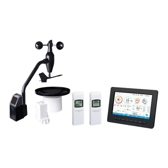
Page 5: Unpacking
2 Unpacking Open your weather station box and inspect that the contents are intact (nothing broken) and complete (nothing missing). Inside you should find the following: Item Description Display Console Wireless Anemometer with built-in: Wind Speed Sensor/ Wind Direction Sensor, Light and UV sensor, Solar panel Wind speed cups (to be attached to anemometer sensor body) Wind vane (to be attached to anemometer sensor body) USB Cable (for console to PC connectivity) - Page 6 Note: Batteries for the wireless anemometer and the rain gauge sensor are all not included. You will need 1 AA size battery, alkaline or Lithium battery (Lithium recommended for colder climates) for each unit. Note: The console operates using an AC adapter. The included adapter is a switching-type adapter and can generate a small amount of electrical interference with the RF reception in the console, when placed too close to the console.
-
Page 7: Overview
3 Overview 3.1 Display console Figure 1: Display console screen memory card slot USB port Power jack reset Figure 2: Display console side views... -
Page 8: Indoor Sensor
3.2 Indoor sensor: Figure 3: Indoor sensor 3 display variations The indoor sensor will display indoor temperature, humidity and barometric pressure alternately. The sensor will use US or metric units, as appropriate for the locale where the unit was sold. -
Page 9: Outdoor Temperature And Humidity Sensor
3.3 Outdoor temperature and humidity sensor: Figure 4: Outdoor temperature and humidity sensor display 3.4 Features • 4.3" TFT full color display • Time and date • Indoor/Outdoor temperature and humidity • Wind speed, gust speed, and wind direction (red arrow icon for the current wind direction and blue dot icon for the previous wind direction on the compass) •... - Page 10 • Barometric history graph (12, 24, 48, or 72 hr.) • Maximum and minimum values for sensor with time stamp • High/low alarm options for sensors • Historical data preserved during power outage on optional SD card • PC software (requires USB connection) •...
-
Page 11: Set Up Guide
4 Set up Guide To complete assembly you will need a Philips screwdriver (size PH0) and a wrench (size M5; included in package). Note: We suggest you assemble all components of the weather station, including console in one location so you can easily test functionality. After testing, place the outdoor sensors in the desired location. -
Page 12: Wireless Anemometer Sensor Assembly
Rain Gauge • Ideally mounted at a height of 4 to 6 feet above the ground. • Ideally located at a horizontal distance of 4 times the height of the nearest obstruction. • Ensure the gauge is mounted level to the ground, away from any horizontal surface that can introduce rain-splashing or surrounding snow buildup. -
Page 13: Install U-Bolts And Metal Plate
1 Wind speed cups 6 LED (red) to indicate data transmission 2 Wind vane 7 Light sensor and UV sensor 3 Connection tube 8 NORTH arrow 4 U-Bolts 9 Solar panel 5 Mounting Pole(not 10 Reset button included) Table 2: Sensor assembly detailed items 4.2.2 Install U-bolts and metal plate Installation of the U-bolts, which are in turn used to mount the sensor package on a pole, requires installation of an included metal plate to receive... -
Page 14: Install Wind Vane
Figure 8: U-Bolts and nuts installed The plate and U-Bolts are not yet needed at this stage but doing this now may help avoid damaging wind vane and wind speed cups later on. Handling of the sensor package with wind vane and speed cups installed to install these bolts is more difficult and more likely to lead to damage. -
Page 15: Install Wind Speed Cups
Figure 9: Wind vane installation diagram 4.2.4 Install wind speed cups Push the wind speed cup assembly onto the shaft on the opposite side of the wind vane, as shown in Figure 10 on the top side. Tighten the set screw, with a Philips screwdriver (size PH0), as shown on the right side. -
Page 16: Install Batteries In Sensor Package
4.2.5 Install Batteries in sensor package Open the battery compartment with a screwdriver and insert 1 AA battery in the battery compartment. The LED indicator on the back of the sensor package (item 6) will turn on for 3 seconds and then flash once every 16.5 seconds indicating sensor data transmission. - Page 17 you keep the anemometer sensor nearby (although preferably not closer than 5 ft. or 1.53m from the display console). This will make any troubleshooting and adjustments easier and avoids any distance or interference related issues from the setup. After setup is complete and everything is working, return here for outdoor mounting.
-
Page 18: Reset Button And Transmitter Led
necessary. Once placed, hand tightens all four nuts, taking care to do so evenly. Do not use a wrench yet! Now you will need to align the whole package in the proper direction by rotating it on top of the mounting pipe as needed. Locate the arrow labeled “NORTH”... -
Page 19: Rain Gauge Sensor Set Up
4.3 Rain Gauge Sensor Set Up See Figure 13 to locate and understand all the parts of the rain gauge sensor once fully assembled. Figure 13: Sensor assembly components 1 Rain collector top 4 Battery door 2 LED Indicator 5 Screw hole 3 Bubble level 6 U-bolt install hole Table 3: Sensor assembly detailed items... -
Page 20: Install Batteries In Rain Gauge Sensor
Figure 14: Rain collector top installation diagram 4.3.2 Install Batteries in rain gauge sensor Remove the battery door on the back of the sensor by sliding it in the direction of the arrow. Insert one AA battery as described and put compartment door back and slide it in the opposite direction to lock. -
Page 21: Mounting
Note: If no LED light up or is lighted permanently, make sure the battery is inserted the correct way or a proper reset is happened. Do not install the batteries backwards. You can permanently damage the outdoor sensor. We recommend lithium batteries for cold weather climates, but alkaline batteries are sufficient for most climates. - Page 22 Figure 16: Rain gauge sensor mounting with u-bolts installation diagram Note: Use the bubble level beside the rain sensor as a guide to verify that the sensor is leveled. Mount with screws The mounting assembly also includes two screws for installation on a flat place.
-
Page 23: Indoor Sensor Set Up
4.4 Indoor Sensor Set Up Note: To avoid permanent damage, please take note of the battery polarity before inserting the batteries. Looking at Figure 18 from left to right the left-most (or bottom) battery is to be installed with its + terminal pointing down, and the other battery with its + terminal pointing up. -
Page 24: Outdoor Temperature And Humidity Sensor Operation
• Use a screw or nail to affix the remote sensor to the wall, as shown on the left side of Figure 19, or • Hang the remote sensor using a string, as shown in right side of Figure Figure 19: Indoor sensor mounting Note: Make sure the sensor is mounted vertically and not lying down on a flat surface. - Page 25 • Indoor/outdoor sensor placement: The sensor will have the longest reach for its signal when mounted or hung vertically. Avoid laying it down on a flat surface. • Electro-Magnetic Interference (EMI). Keep the console several feet away from computer monitors and TVs. •...
-
Page 26: Console Display
4.7 Console Display See 错误!未找到引用源。 to help you identify elements of the console’s display screen. Figure 20: Display Console Screen Layout Description Description Outdoor temperature Last lightning strikes detected time / distance; daily counts (optional sensor) Outdoor Feels Like/Dew Indoor humidity point/Humidity/10Min. -
Page 27: Initial Display Console Set Up
Description Description RF signal bar for PM2.5 Multi-channel temperature and sensor(optional sensor) humidity sensor cycle display mode icon(optional sensor) Sunrise / Sunset Time Multi-channel temperature and humidity sensor channel number (optional sensor) Wi-Fi signal bar Rain fall Daily/Event/Hourly/Weekly/ Monthly/Yearly Low battery power indicator for RF signal bar for rain fall each sensor nsor... -
Page 28: Key Functions
Dark Background Display Light Background Display Note: Sunrise/sunset time display will only work properly when GEO location has been set up correctly. GEO setup can be carried out under setup menu. Key functions Figure: Buttons around the display There is a set of eight keys on the bottom of the display console. The following tables briefly explains the function of these keys. - Page 29 Icon Description Brightness control key Press this key to decrease the brightness Brightness control key Press this key to enhance the brightness Backlight on/off key Press this key to on/off the backlight Background key Press this key to choose between dark background display and light background display Pressure display key Press this key to choose the display between Absolute pressure and...
- Page 30 0 to 10 70-80 10-20 80-90 20-30 90-100 30-40 100-110 40-50 > 110 Note: please refer to the online manual for colorful display. Humidity Icon Color Humidity Range Color Humidity Range (%) Ring Ring 0%, No signal or 50 to 60 dashes 1 to 10 60 to 70...
- Page 31 40 to 50 100% Current wind direction indication , 10-minute average wind direction indication Hourly Rainfall Icon Hourly Rain (in) Icon Hourly Rain (in) Color Ring 0.6 to 0.8 0 to 0.2 0.8 to 1 0.2 to 0.4 1 to 1.2 0.4 to 0.6 1.2 to 1.4 Multiple Channel Selection and Scroll Mode...
- Page 32 History Mode View and Reset MAX/MIN While in normal display, press the key once to view and reset minimum and maximums. Figure: Max/Min Screen Icon Description Selection key Press this key to select the weather MAX/MIN record which need to clear Selection key Press this key to select the weather MAX/MIN record which need to clear...
- Page 33 ”Clear the Max/Min record?”. Press key to popup Message Box key or key to select YES or NO. Press the key or key to confirm the selection. Up arrow key Press this key to change the activated option field Down arrow key Press this key to change the activated option field History key Press this key to select History data display.
- Page 34 Page Select key Press this key to enter particular page of the history data. Each page contains 16sets data. Scroll left key Press this key to view the left of the scrollable area. Scroll right key Press this key to view the right of the scrollable area.
- Page 35 While in History Record Mode, press the key to enter the page selection mode: Figure : view a specific page of history Screen Press to select a digit in a number, press key to change the number. Press to change the activated option field, toggle OK or Cancel then press key to confirm.
- Page 36 Press to shift the data display of 12/24/48/72H. Press to view the graph of the following data: • Indoor outdoor humidity • Dew Point and Feels like • Indoor outdoor temperature • Wind speed and Gust • Wind Direction • •...
- Page 37 Note: Channel names can be edited on this page Setting Mode While in normal display, press the key to enter Setting Mode. You can select the below sub-mode by pressing the...
- Page 38 Figure : Setup Menu Screen Icon Description Select key Press this key to select the unit or scrolls the value Select key Press this key to select the unit or scrolls the value. Left key Press this key to select the set value. Right key Press this key to select the set value.
- Page 39 Figure : Time and date Setup Screen Time setting (hour/minute/second) Press key to select time setting field, and the hour digit will turn red, press key to change the hour setting. Press to set the minute, the minute digit will turn red, press the key to change the minute setting.
- Page 40 change the time zone setting. Press key to select Update field, press the key to update the time immediately. Automatically synchronize with internet time server key to tick” The time server is time.nist.gov. Press the Automatically synchronize with internet time server” and press” update” to synchronize with time server immediately.
- Page 41 Solar Rad. Unit Press to change the solar radiation units of measure between W/m^2, lux and Multi Channel Sensor In Multi channel sensor Setup Screen, you can rename the multi-channel temperature and humidity sensor or register the sensor again while the sensor lost connection to console display.
- Page 42 Figure : rename the sensor Screen Press key to select Register setting field, press the key to register the selected sensor Backlight setting While in Menu Setting Mode, press key to select Backlight Setup field, press key to enter backlight Setup mode:...
- Page 43 Figure : Backlight Setting Screen Automatic control backlight: select this option, the backlight will auto turn on and off according the set time Turn on the backlight: set the time of turning on backlight Turn off the backlight: set the time of turning off backlight Automatic brightness adjustment: select this option, the brightness will change according to the light intensity measured from outdoor sensor Maximum brightness: set the maximum brightness while it is...
- Page 44 Down arrow key Press this key to change the activated option field Return key Press this key to return to previous mode If the auto backlight turn-on time has been set, you can press key to turn off the backlight within the turn on time. Backlight will turn on again automatically at next turn on time.
- Page 45 Ecowitt Weather Site: https://www.ecowitt.net Ecowitt’s new weather server that can host a bunch of sensors that other services don’t support at this time. Table: Supported weather services Note: If you are testing the setup with the outdoor sensor package nearby and indoor, you may want to consider connecting to Wi-Fi, but not yet configuring any of the weather services.
- Page 46 Then, after final outdoor installation, come back and change the password after clearing console history. That will start uploading to the services with a clean slate. Press key to enter Weather Server set up mode. The device can be configured to send real-time data to wunderground.com®. Enter the Station ID and Password obtained from Wunderground.com.
- Page 47 1) Set Station ID. Press to highlight the Station ID. Enter your station ID. Press to display the keyboard. Press to scroll Press the “OK” to the character and press to select the character. button to confirm. Press to return to the setup page. 2) Set Station Key.
- Page 48 1. Click My Profile and select My Devices to register your station 2. Select Add New Device. 3. Find Personal Weather Station. Select ‘other’ and click ‘Next’.
- Page 49 4. Select ‘Address’ or ‘Manual’ option, and find your local position. Press ‘Next’.
- Page 50 5. This time you will be asked details about your weather station. Go ahead and fill out the form. 6. After completing the weather station, you will see station ID and key/password. 7. Take note of the station ID and key/password and enter it in the Weather Server:...
- Page 51 Figure 31: Weather Server setup screen scroll value scroll value Scroll field Scroll field return to down down Setup 1) Set Station ID. Press to highlight the Station ID. Enter your station...
- Page 52 ID. Press to display the keyboard. Press to scroll Press the “OK” to the character and press to select the character. button to confirm. Press to return to the setup page. 2) Set Station Key. Press to highlight the station key. Enter your password obtained from according weather server.
- Page 53 There are also some very useful mobile apps. The URLs provided here go to the Web version of the application pages. You can also find them directly from the iOS or Google Play stores: ⚫ WunderStation: iPad application for viewing your station’s data and graphs https://itunes.apple.com/us/app/wunderstation-weather-from-your-neigh borhood/id906099986 ⚫...
- Page 54 ⚫ Weather Underground: Forecast: iOS and Android application for forecasts https://itunes.apple.com/us/app/weather-underground-forecast/id486154808 https://play.google.com/store/apps/details?id=com.wunderground.android.we ather&hl=en...
- Page 55 Connects to wunderground.com https://itunes.apple.com/us/app/pws-weather-station-monitor/id713705929 Registering with and using Ecowitt Weather You can also use the Ecowitt Weather server to monitor and record all your sensors’ data. Configure as follows: ⚫ On the Weather Server page, set the reporting interval time(default: 1 minute).
- Page 56 When select device address on map, please wait until the map displays before selecting your address. You may add a shortcut to the ecowitt.net website on the home page of your phone so that you can visit it just like opening an app.
- Page 57 Graph display List display...
- Page 58 Weather Map Email Alerts...
- Page 59 For highly experienced users, it offers the option to send data to the user’s own server. Press the “setup” button to enter Customized setup screen, Figure : Server setup screen Select Enable button and select the protocol type. The website should has the same protocol with Wunderground or Ecowitt. Input all the information needed.
- Page 60 Connect Console to Your Router: Wi-Fi scan Entering this mode, system will display all the available Wi-Fi networks. Select the SSID that you want console to be connected with (only supports 2.4GHz band Wi-Fi network ) , and enter passer word as required.
- Page 61 Press key to select the Wi-Fi network. Press key to confirm and enter the password. Press key to return to normal display mode. It is possible that your network is not listed when Wi-Fi Scan is performed. Press button and restart Wi-Fi Scan, this will usually solve the problem. Only after connect to WLAN you can upload the data to weather website.
- Page 62 page. to highlight the “OK” button beside “Connect ” to start connecting. 4) Press After connected successfully, the status will display” Connected”. Background While in Menu Setting Mode, press key to select Background Setup field, press key to choose between dark background display and light background display...
- Page 63 Alarm Setting Mode Icon Description Select key Press this key to select the unit or scrolls the value Select key Press this key to select the unit or scrolls the value. Left key Press this key to select the set value. Right key Press this key to select the set value.
- Page 64 Calibration Mode Icon Description Select key Press this key to select the unit or scrolls the value Select key Press this key to select the unit or scrolls the value. Left key Press this key to select the set value. Right key Press this key to select the set value.
- Page 65 Temperature Offset Current Red Spirit or Mercury Value Thermometer (1) Humidity Offset Current Sling Psychrometer (2) Value Offset Current Calibrated laboratory grade Barometer Value barometer Offset Current Local airport (3) Barometer Value Wind Offset Current GPS, Compass (4) Direction Value Solar Gain 1.00...
- Page 66 Place the sensor in a shaded, controlled environment next to the fluid thermometer, and allow the sensor to stabilize for 3 hours. Compare this temperature to the fluid thermometer and adjust the console to match the fluid thermometer. (2) Humidity is a difficult parameter to measure electronically and drifts over time due to contamination.
- Page 67 the sensor on a 5’ pole: Distance = 4 x (20 – 5)’ = 60’ or =4 x (6.10-1.52)=18.32m. Many installations are not perfect and installing the weather station on a roof can be difficult. Thus, you can calibrate for this error with a wind speed multiplier.
- Page 69 Note: To calibrate the optional soil moisture sensor, please refer to the manual of the WH51 soil moisture senor. To calibrate the PM2.5 sensor, you’ll need to find a reliable source, such as professional devices from your local air quality service. To calibrate the temp and humidity sensor, please refer to section 4.9.19.
- Page 71 Factory reset Re-register indoor transmitter Press key to select re-register indoor transmitter. Press ”Register a new indoor transmitter?” Press key to popup the Message Box to select Yes or No. Press the key to confirm the selection.
- Page 72 Re-register outdoor transmitter Please reference section 5.13.1. Procedures and settings are similar to re-register indoor transmitter. Automatic Clear Max/Min To turn on/off automatically clear Max/Min record at 0:00hr every day. Press key to select Automatic clear Max/Min. Press key to switch on/off.
- Page 73 Backup data Press key to select Backup data. Press key to popup the ”Copy history data to SD card?” Press Message Box to select OK or Cancel. Press the key to confirm the selection. Note: You need to insert a SD card(not included) into the console before using this function.
- Page 74 Wind speed Beaufort Description number 0 - 1 mph, or 0 - 1.6 km/h Calm 1 - 3 mph, or 1.6 - 4.8 km/h Light air 3 - 7 mph, or 4.8 - 11.3 km/h Light breeze 7 - 12 mph, or 11.3 -1 9.3 km/h Gentile breeze 12 - 18 mph, or 19.3 - 29.0 km/h Moderate breeze...
- Page 75 Pressure decreases for Pressure decreases for Pressure rapidly a sustained period of a sustained period of decreases time, and temperature time ≤0℃ Storm Snowy Pressure rapidly decreases, temperature≤0℃ Lightning Alert The lightning icon will appear if the Dew Point exceeds 70 F. This means there is a chance of lightning storms forming.
- Page 76 conditions, including weather radar, weather models, and detailed mapping of ground conditions. Moon Phase In the event the moon phase is 100%, the icon will appear in its place. In the event of 0%, the word “New Moon” will appear in its place. Moon Phase Image Moon Phase...
- Page 77 Day 10 Day 23 Day 11 Day 24 Day 12 Day 25 Day 13 Day 26 Full Moon New Moon...
- Page 78 5 Maintenance The following steps should be taken for proper maintenance of your station Clean Rain Gauge Check the rain gauge every 3 months. Rotate the funnel counter-clockwise and lift it up. Clean the funnel and bucket with a damp cloth to remove any dirt, debris and insects.
- Page 79 Figure: Rain gauge maintenance...
- Page 80 Clean Solar Radiation Sensor and Solar Panel The solar radiation sensor and solar panel of the outdoor sensor array need to be cleaned with a non-abrasive slightly damp cloth every 3 months. Replacing Batteries Regularly Batteries of the outdoor sensor array need to be replaced every 1-2 years for environmental friendly.
- Page 81 6 Troubleshooting Guide Look through the following table and locate an issue or problem you are experiencing in the left column and read possible solutions in the right column. Problem Solution Outdoor sensor Check that the outdoor transmission LED is flashing not reporting to normally.
- Page 82 Problem Solution Intermittent There may be a temporary loss of communication due to problems with signal quality issues caused by electrical interference or outdoor sensor other location related factors (obstacles along line of reception on sight). console To troubleshoot, install a fresh set of batteries in the remote sensor console.
- Page 83 Problem Solution Indoor and The procedure here is that same as for outdoor/indoor Outdoor temperature. The sensors should agree within 10 % (the Humidity do sensor accuracy is ± 5 %) not agree If these values still disagree, use calibration offsets for during indoor one or both sensors (see section 5.3) to adjust to a known testing...
- Page 84 Problem Solution Data not Confirm your station ID is correct. The station ID is all reporting to caps, and the most common issue is substituting a capital Wunderground. letter O for a 0 (zero) or vice versa. Please note the digit 0 can only occur in the last part of the station ID (which is a station number in a city).
- Page 85 7 Glossary of Common Terms TERM DESCRIPTION ABSOLUTE AIR PRESSURE Absolute air pressure is the air pressure ABSOLUTE BAROMETRIC registered on a barometer without regard PRESSURE to altitude. BAROMETER A barometer is a device that measures the pressure of the air pushing on it—this measurement is called the barometric pressure.
- Page 86 TERM DESCRIPTION HYGROMETER An instrument that measure relative humidity of the air. This is expressed as a percentage between 0% and 100%. INCHES OF MERCURY This is the common unit of measurement (inHg) for air pressure in the United States. It refers to the length of a standard column of mercury (a liquid metal) that can be pushed up by the ambient air pressure.
- Page 87 TERM DESCRIPTION Thin-Film-Transistor, a type of LCD screen. ULTRA VIOLET INDEX The ultraviolet index or UV-Index (UVI) is an international standard measurement of the strength of sunburn-producing ultraviolet (UV) radiation at a particular place and time. The purpose of the UV Index is to help people effectively protect themselves from UV radiation.
- Page 88 8 Specifications Note: Out of range values will be displayed using “---”: Outdoor sensor Specification Transmission distance 100 m (330 ft.) open field 433/ 868/ 915MHz depending on location RF Frequency (North American: 915MHz; Europe: 868MHz; Other areas: 433MHz) -40° C – 60° C (-40° F - 140° F) Temperature range Temperature accuracy ±...
- Page 89 Indoor sensor Specification -10° C – 60° C (14° F - 140° F) Temperature range Temperature resolution 0.1° C, or 0.1° F Humidity range 10% ~ 99% Humidity resolution 300 – 1,100 hPa (8.85 – 32.5 inHg) Barometric pressure range ±...
- Page 90 9 Warranty Information We disclaim any responsibility for any technical error or printing error, or the consequences thereof. All trademarks and patents are recognized. We provide a 1-year limited warranty on this product against manufacturing defects, or defects in materials and workmanship. This limited warranty begins on the original date of purchase, is valid only on products purchased, and only to the original purchaser of this product.
Need help?
Do you have a question about the HP2552 and is the answer not in the manual?
Questions and answers