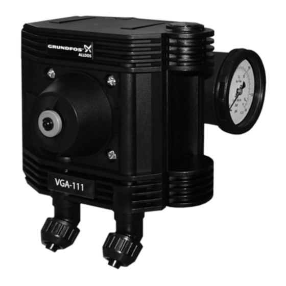
Grundfos Vaccuperm VGA-111 Installation And Operating Instructions Manual
Vacuum regulator
Hide thumbs
Also See for Vaccuperm VGA-111:
- Installation and operating instructions manual (220 pages)

Subscribe to Our Youtube Channel
Related Manuals for Grundfos Vaccuperm VGA-111


Summary of Contents for Grundfos Vaccuperm VGA-111
- Page 1 GRUNDFOS INSTRUCTIONS Vaccuperm VGA-111 Vacuum regulator Installation and operating instructions Other languages http://net.grundfos.com/qr/i/95714202...
-
Page 2: Table Of Contents
1.2 Safety advice for handling chlorine If you require further information, or if problems occur that are not 1.3 Protective equipment described in detail in this manual, please contact Grundfos. 1.4 First aid in case of accidents 1.5 Handling chlorine containers 1.1 Symbols used in this document... -
Page 3: Protective Equipment
1.3 Protective equipment 1.4 First aid in case of accidents 1.3.1 Personal protective equipment 1.4.1 First aid after inhaling chlorine The operating authority of a chlorine gas dosing system has to 1. Keep calm. provide respiratory equipment (full-sight gas mask), personally 2. -
Page 4: Handling Chlorine Containers
1.5 Handling chlorine containers 1.5.3 Basic rules Chlorine is stored in grey steel cylinders or drums in lockable Warning chlorine rooms. Due to safety precautions, chlorine containers Handling of chlorine containers only by experienced are only filled up to 95 % of their capacity. personnel. -
Page 5: Chlorine Rooms
1.6 Chlorine rooms 1.6.2 Labelling of chlorine rooms In Germany, according to DIN 4844, the following warning signs Chlorine rooms are rooms, where a chlorine gas dosing system must be installed outside the entrance of a chlorine room: and/or chlorine containers are located. The chlorine in these rooms is under pressure. -
Page 6: Introduction
The responsibilities of the user: • Read this manual before operating the product. • Be trained by qualified Grundfos personnel in the operation of the product. • Observe the relevant regulations governing safety in the workplace and accident prevention. -
Page 7: Type Key Of The Vga-111 Vacuum Regulator
2.6 Type key of the VGA-111 vacuum regulator The type key serves for the identification of the product, not for configuration. Code Example VGA-111 Vaccuperm Gas Advanced Installation Directly on the cylinder Wall-mounting Header line Directly on the cylinder/header line Connection G 3/4 U.S. -
Page 8: Technical Data
3. Technical data 3.2 Connections 3.1 General technical data Vacuum connection for for hose 8/11 mm the dosing regulator Permissible medium Pressure connection to for hose 8/11 mm Maximum flow 4000 g/h the adsorption filter Empty signal Optical indication union nut 1" Pressure connection at Approx. -
Page 9: Physical And Chemical Data Of Chlorine
3.5 Physical and chemical data of chlorine Under normal conditions of pressure and temperature, chlorine is a yellowish green gas with a pungent odour, which exists as Cl molecule. It is not flammable, but can promote the flammability of metals, hydrocarbons, etc. -
Page 10: Design And Function
4. Design and function 4.2 Functional principle 4.2.1 Vacuum regulator 4.1 Description of the device The vacuum regulator is a pressure reducing valve, which reduces the overpressure from the chlorine tank side to the negative pressure on the vacuum side. The valve at the vacuum regulator opens, when after switching on the injector a sufficient vacuum has built up at the outlet side. - Page 11 4.2.2 Vacuum chlorine gas dosing system Fig. 10 Principle of a vacuum chlorine gas dosing system Vacuum regulator (B) Pos. Description The vacuum regulator is a pressure reducing valve, which reduces the overpressure from the chlorine tank side to the Chlorine cylinder negative pressure on the vacuum side.
-
Page 12: Assembly And Installation
5. Assembly and installation 5.1 Selection of vacuum lines Warning Observe section 1. Safety instructions. The vacuum needed for the transport of chlorine gas is built up by the injector, and maintained by the vacuum lines. Rigid PVC pipes or flexible PE hoses are used as vacuum lines. The following tables show the recommended diameter of vacuum lines, depending on the line length and dosing quantity. -
Page 13: Connecting The Vacuum Regulator
5.2 Connecting the vacuum regulator 5.3 Connecting the liquid trap (option) Warning Make sure that the mains voltage indicated on the name plate corresponds with the local voltage. Before connecting, make sure that the valves of all Wrong voltage can lead to damages of the product. chlorine containers are closed. -
Page 14: Startup
6. Startup Checking the tightness with nitrogen 1. Close all chlorine container valves. Warning 2. Open container connection valves and all shut-off valves up to The chlorine gas dosing system can only be started the chlorine gas dosing system. after its good condition has been checked by an 3. -
Page 15: Chlorine Extraction
Checking the pressure connections (after change of 6.2.2 Container valves container) Operate the valves at the chlorine containers only manually 1. Open the container valve and immediately close it again. without force. Close the valves of full or empty chlorine containers with closing nut (marked chlorine or Cl ) and gasket. -
Page 16: Operation
7. Operation 7.3 Switching off the chlorine gas dosing system The vacuum regulator doesn't have to be operated. When it is 7.3.1 Emergency stop in case of gas escape correctly connected, and a sufficient vacuum has built up on the Warning outlet side, the vacuum regulator starts operation automatically. -
Page 17: Fault Finding
10. Disposal This product and all its associated parts must be disposed of in an environmentally friendly manner. Use appropriate waste collection services. If this is not possible, contact the nearest Grundfos company or service workshop. - Page 18 FR: Déclaration de conformité UE GR: ∆ήλωση συμμόρφωσης ΕΕ Nous, Grundfos, déclarons sous notre seule responsabilité, que les Εμείς, η Grundfos, δηλώνουμε με αποκλειστικά δική μας ευθύνη ότι τα produits VGA-111, VGA-113, VGA-117, VGA-146, VGB-103, VGS-141, προϊόντα VGA-111, VGA-113, VGA-117, VGA-146, VGB-103, VGS-141, VGS-143, VGS-145, VGS-147, VGS-148, auxquels se réfère cette...
- Page 19 Declaration of conformity EAC Установки вакуумные для дозирования газов типа Vaccuperm сертифицированы на соответствие требованиям Технических регламентов Таможенного союза: ТР ТС 004/2011 «О безопасности низковольтного оборудования»; ТР ТС 010/2011 «О безопасности машин и оборудования»; ТР ТС 020/2011 «Электромагнитная совместимость технических средств». Сертификат...
- Page 21 20th km. Athinon-Markopoulou Av. Phone: +55-11 4393 5533 Telefax: +64-9-415 3250 Turkey P.O. Box 71 Telefax: +55-11 4343 5015 GRUNDFOS POMPA San. ve Tic. Ltd. Sti. Norway GR-19002 Peania Gebze Organize Sanayi Bölgesi Bulgaria GRUNDFOS Pumper A/S Phone: +0030-210-66 83 400...
- Page 22 95714202 0419 ECM: 1260453 www.grundfos.com...
Need help?
Do you have a question about the Vaccuperm VGA-111 and is the answer not in the manual?
Questions and answers