Table of Contents
Advertisement
Quick Links
OM-01934-OB02
CDSW
October 10, 1983
Rev. H 12/12/01
INSTALLATION, OPERATION,
AND MAINTENANCE MANUAL
WITH PARTS LIST
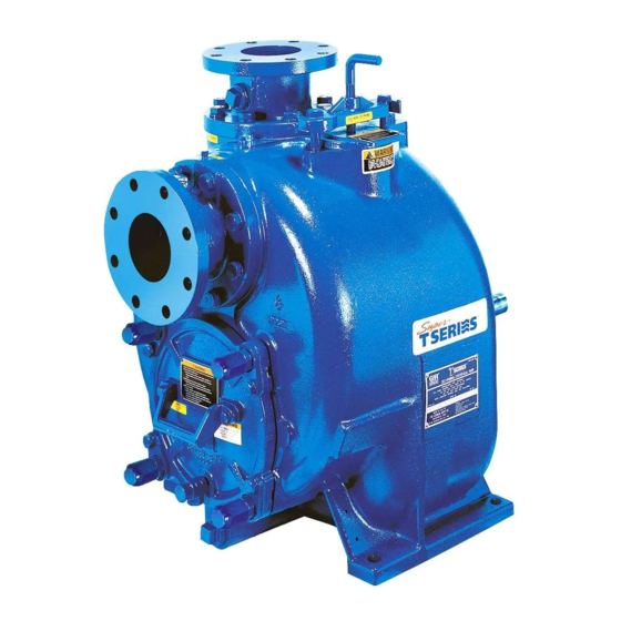
T---SERIES PUMP
MODEL
T6A61-B
INCLUDING: /F, /FM
THE GORMAN-RUPP COMPANY D MANSFIELD, OHIO
GORMAN-RUPP OF CANADA LIMITED
ST. THOMAS, ONTARIO, CANADA
D
Printed in U.S.A.
e
Copyright by the Gorman-Rupp Company
Advertisement
Table of Contents

Subscribe to Our Youtube Channel
Related Manuals for GORMAN-RUPP T6A61-B


Summary of Contents for GORMAN-RUPP T6A61-B
- Page 1 Rev. H 12/12/01 INSTALLATION, OPERATION, AND MAINTENANCE MANUAL WITH PARTS LIST T---SERIES PUMP MODEL T6A61-B INCLUDING: /F, /FM THE GORMAN-RUPP COMPANY D MANSFIELD, OHIO GORMAN-RUPP OF CANADA LIMITED ST. THOMAS, ONTARIO, CANADA Printed in U.S.A. Copyright by the Gorman-Rupp Company...
- Page 2 TABLE OF CONTENTS INTRODUCTION ..........PAGE I --- 1 SAFETY --- SECTION A .
-
Page 3: Table Of Contents
TABLE OF CONTENTS (continued) TROUBLESHOOTING --- SECTION D ......PAGE D --- 1 PREVENTIVE MAINTENANCE . - Page 4 If there are any questions regarding the pump or its application which are not covered in this manual or in other literature accompanying this unit, please contact your Gorman-Rupp distributor, or write: The Gorman-Rupp Company Gorman-Rupp of Canada Limited P .O.
- Page 5 SAFETY --- SECTION A These warnings apply to T Series basic Do not attempt to pump volatile, corro- pumps. Gorman-Rupp has no control sive, or flammable materials which may over or particular knowledge of the damage the pump or endanger person- power source which will be used.
- Page 6 OM -- 01934 T SERIES This pump is designed to handle materi- Use lifting and moving equipment in als which could cause illness or injury good repair and with adequate capacity through direct exposure or emitted to prevent injuries to personnel or dam- fumes.
- Page 7 For further assistance, contact your Gorman-Rupp Most of the information pertains to a standard distributor or the Gorman-Rupp Company. static lift application where the pump is posi- tioned above the free level of liquid to be pumped.
- Page 8 If the maximum shelf life has been exceeded, or if anything appears to be abnormal, contact your Gorman-Rupp distributor or the factory to deter- Materials mine the repair or updating policy. Do not put the pump into service until appropriate action has Either pipe or hose maybe used for suction and been taken.
- Page 9 T SERIES OM -- 01934 Fittings compatible with the liquid being pumped. If hose is used in suction lines, it must be the rigid-wall, rein- Suction lines should be the same size as the pump forced type to prevent collapse under suction. Us- inlet.
- Page 10 OM -- 01934 T SERIES Suction Line Positioning If it is necessary to position inflow close to the suc- tion inlet, install a baffle between the inflow and the The depth of submergence of the suction line is suction inlet at a distance 1 1/2 times the diameter critical to efficient pump operation.
- Page 11 If the application involves a high discharge overall pumping efficiency. Therefore, it is recom- head, gradually close the discharge mended that a Gorman-Rupp Automatic Air Re- throttling valve before stopping the pump. lease Valve be installed in the bypass line.
- Page 12 When properly installed and correctly adjusted to the specific hydraulic operating conditions of the Some leakage (1 to 5 gallons [3.8 to 19 application, the Gorman-Rupp Automatic Air Re- liters] per minute) will occur when the lease Valve will permit air to escape through the by- valve is fully closed.
- Page 13 However, if multiple Air Re- When mounted at the Gorman-Rupp factory, driver lease Valves are installed in a system, the bleeder and pump are aligned before shipment. Misalign- lines may be directed to a common manifold pipe.
- Page 14 OM -- 01934 T SERIES When checking alignment, disconnect the power source to ensure that the pump will remain inoperative. Adjusting the alignment in one direction may alter the alignment in another direc- Figure 6B. Aligning Non-Spider Type Cou- tion. check each procedure after altering plings alignment.
- Page 15 T SERIES OM -- 01934 Do not operate the pump without the guard in place over the rotating parts exposed rotating parts can catch cloth- ing, fingers, or tools, causing severe in- jury to personnel. MISALIGNED: MISALIGNED: ALIGNED: SHAFTS SHAFTS SHAFTS PARALLEL AND NOT PARALLEL...
- Page 16 OM -- 01934 T SERIES OPERATION --- SECTION C Review all SAFETY information in Section A. 1. The pump is being put into service for the first time. Follow the instructions on all tags, labels and de- 2. The pump has not been used for a consider- cals attached to the pump.
- Page 17 Lines With a Bypass Liquid Temperature And Overheating If a Gorman-Rupp Automatic Air Release Valve has been installed, the valve will automatically open to allow the pump to prime, and automatically close The maximum liquid temperature for this pump is after priming is complete (see INSTALLATION for 160_ F (71_ C).
- Page 18 OM -- 01934 T SERIES valve with a substitute which has not been speci- fied or provided by the Gorman-Rupp Company. Strainer Check If the application involves a high discharge head, gradually close the discharge throttling valve before stopping the pump.
- Page 19 OM -- 01934 T SERIES AND REPAIR). Bearing overheating can also be curately by placing a contact-type thermometer against the housing. Record this temperature for caused by shaft misalignment and/or excessive vi- future reference. bration. A sudden increase in bearing temperature is a warning that the bearings are at the point of failing When pumps are first started, the bearings may to operate properly.
-
Page 20: Troubleshooting
T SERIES OM -- 01934 TROUBLESHOOTING --- SECTION D Review all SAFETY information in Section A. Before attempting to open or service the pump: 1. Familiarize yourself with this manu- 2. Lock out or disconnect the power source to ensure that the pump will remain inoperative. - Page 21 OM -- 01934 T SERIES TROUBLE POSSIBLE CAUSE PROBABLE REMEDY Air leak in suction line. Correct leak. PUMP STOPS OR FAILS TO DELIVER Lining of suction hose collapsed. Replace suction hose. RATED FLOW OR PRESSURE Leaking or worn seal or pump gasket. Check pump vacuum.
-
Page 22: Preventive Maintenance
Gorman-Rupp pump. For specific questions con- For new applications, a first inspection of wearing cerning your application, contact your Gorman- parts at 250 hours will give insight into the wear rate Rupp distributor or the Gorman-Rupp Company. - Page 23 OM -- 01934 T SERIES Preventive Maintenance Schedule Service Interval* Item Daily Weekly Monthly Semi- Annually Annually General Condition (Temperature, Unusual Noises or Vibrations, Cracks, Leaks, Loose Hardware, Etc.) Pump Performance (Gauges, Speed, Flow) Bearing Lubrication Seal Lubrication (And Packing Adjustment, If So Equipped) V-Belts (If So Equipped) Air Release Valve Plunger Rod (If So Equipped)
-
Page 24: Pump Maintenance And Repair
MAINTENANCE AND REPAIR OF THE WEARING PARTS OF THE PUMP WILL MAINTAIN PEAK OPER- ATING PERFORMANCE. STANDARD PERFORMANCE FOR PUMP MODEL T6A61-B Based on 70_ F (21_ C) clear water at sea level Contact the Gorman-Rupp Company to verify per- formance or part numbers. - Page 25 OM -- 01934 T SERIES SECTION DRAWING Figure 1. Pump Model T6A61---B PAGE E -- 2 MAINTENANCE & REPAIR...
-
Page 26: Parts Lists
PARTS LIST Pump Model T6A61---B (From S/N 791258 up) If your pump serial number is followed by an “N”, your pump is NOT a standard production model. Contact the Gorman-Rupp Company to verify part numbers. ITEM PART NAME PART MAT’L... - Page 27 OM -- 01934 T SERIES SECTION DRAWING Figure 2. 44163---060 Repair Rotating Assembly PAGE E -- 4 MAINTENANCE & REPAIR...
- Page 28 OM -- 01934 T SERIES PARTS LIST 44163---060 Repair Rotating Assembly ITEM PART NAME PART MAT’L ITEM PART NAME PART MAT’L NUMBER CODE NUMBER CODE SHIPPING PLUG 11495B 15079 IMPELLER 10958 17070 SHIM SET 13131 17040 SEAL ASSEMBLY 46512--- 047 --- --- --- BRG HOUSING O-RING S1676...
-
Page 29: Pump And Seal Disassembly And Reassembly
OM -- 01934 T SERIES PUMP AND SEAL DISASSEMBLY 1. Familiarize yourself with this man- ual. AND REASSEMBLY 2. Disconnect or lock out the power source to ensure that the pump will Review all SAFETY information in Section A. remain inoperative. 3. -
Page 30: Rotating Assembly Removal
T SERIES OM -- 01934 quired since it must be replaced as a complete unit. Turn Individual parts are not sold separately. Counterclockwise Lathe Dog Arm Rotating Assembly Removal (Figure 2) “V” Notch Heavy Shaft Key Bar Stock The rotating assembly may be serviced without Impeller Shaft disconnecting the suction or discharge piping;... -
Page 31: Impeller Removal
OM -- 01934 T SERIES Install the tee, and screw the handles into the tee. assembly. Disassemble the shaft and bearings Use caution when lifting the rotating assembly to only when there is evidence of wear or damage. avoid injury to personnel or damage to the assem- bly. -
Page 32: Shaft And Bearing Reassembly And Installation
T SERIES OM -- 01934 Clean the bearings thoroughly in fresh cleaning Inspect the shaft for distortion, nicks or scratches, solvent. Dry the bearings with filtered compressed or for thread damage on the impeller end. Dress air and coat with light oil. small nicks and burrs with a fine file or emery cloth. -
Page 33: Seal Installation
OM -- 01934 T SERIES Lubricate the bearing housing as indicated in LU- movement has occurred, use a suitable sized sleeve and a press to reposition the bearings BRICATION. against the shaft shoulders. Seal Installation If heating the bearings is not practical, use a suit- (Figures 2 and 5) able sized sleeve, and an arbor (or hydraulic) press to install the bearings on the shaft. - Page 34 T SERIES OM -- 01934 SEAL PLATE RETAINER SPRING IMPELLER O-RINGS IMPELLER SHIMS IMPELLER SHAFT STATIONARY ELEMENT BELLOWS STATIONARY SEAT SPRING CENTERING ROTATING WASHER ELEMENT DRIVE BAND Figure 5. 46512-- 047 Seal Assembly This seal is not designed for operation at A new seal assembly should be installed any time the old seal is removed from the temperatures above 160...
-
Page 35: Impeller Installation
OM -- 01934 T SERIES NOTE Install the stationary seal element in the stationary seat. Press this stationary subassembly into the If the rotating assembly has been installed in the seal plate bore until it seats squarely against the pump casing, this clearance may be measured by bore shoulder. -
Page 36: Suction Check Valve Installation
Never NOTE replace this valve with a substitute which has not If the suction or discharge flanges were removed, been specified or provided by the Gorman-Rupp replace the respective gaskets, apply ‘Permatex Company. Aviation No. 3 Form-A-Gasket’ or equivalent com-... -
Page 37: Lubrication
OM -- 01934 T SERIES guards in place over the rotating parts. the middle of the gauge. When lubrication is re- Exposed rotating parts can catch cloth- quired, add SAE No. 30 non-detergent oil through the hole for the air vent (7). Do not over-lubricate. ing, fingers, or tools, causing severe in- Over-lubrication can cause the bearings to over- jury to personnel. - Page 38 For U.S. and International Warranty Information, Please Visit www.grpumps.com/warranty or call: U.S.: 419−755−1280 International: +1−419−755−1352 For Canadian Warranty Information, Please Visit www.grcanada.com/warranty or call: 519−631−2870 THE GORMAN-RUPP COMPANY D MANSFIELD, OHIO GORMAN-RUPP OF CANADA LIMITED ST. THOMAS, ONTARIO, CANADA...
Need help?
Do you have a question about the T6A61-B and is the answer not in the manual?
Questions and answers