
Related Manuals for Apex Tool Group Cleco 55PHH


Summary of Contents for Apex Tool Group Cleco 55PHH
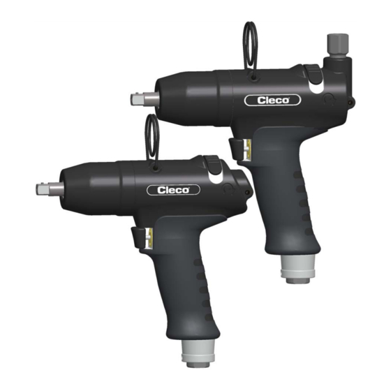
- Page 1 Instruction Manual P1994BA/EN 2014-06 55PHH Pulse nutsetter without shutoff For additional product information visit our website at http://www.apexpowertools.eu...
- Page 2 H – 3 Chamber motor Disclaimer: Apex Tool Group reserves the right to modify, supplement or improve the document or the product without prior announcement. This document may not be reproduced in any way, shape or form, in full or parts thereof, or copied to another natural or machine readable language or to a data carrier, whether electronic, mechanical, optical or otherwise without the express permission of Apex Tool Group.
-
Page 3: Table Of Contents
Contents Safety Warnings and notes..................... 5 Basic requirements for safe working practices............5 Operator training ......................6 Personal protective equipment..................6 Designated use ......................6 Noise and vibrations....................6 Items supplied Product description Operation and functional elements................7 Options ........................8 Before initial operation Air supply........................ - Page 4 Performance Data ..................... 37 Ambient conditions ....................37 Service Disposal P1994BA/EN 2013-09 P1994BA-EN_2014-06_55PHHIVZ.fm, 11.06.2014...
-
Page 5: Safety
Always carry out assembly according to Chapter 8 Spare parts, page 25. Use only accessory parts authorized by Apex Tool Group (see product catalog). Only use screw bits for machine-controlled fastening tools. Make sure that the screw bits are securely inserted. -
Page 6: Operator Training
Safety Operator training Users must be given instruction in the correct usage of the tool. The operator must make the Operating Manual accessible to users and make sure that the users have read and understood it. The tool may only be connected, used, serviced and repaired by qualified persons. -
Page 7: Items Supplied
Items supplied Items supplied Check shipment for transit damage and ensure that all items have been supplied: 1 55PHH 1 This instruction manual 1 Declaration of Conformity 1 Hex wrench (WAF 2) Product description Operation and functional elements 55PHHA… Alternative position 55PHH…... -
Page 8: Options
Before initial operation Options Protective sleeve Order No. 937449PT – 55PHH… Order No. 937444PT – 55PHHA… Vibration absorber Order No. 935965 – 55PHHA… Quick change chuck adapter Order No. 935472 Before initial operation Air supply Parameter Data Air hose Inner diameter 3/8" (ø 9.5 mm), maximum length 5 m ... -
Page 9: Change Air Inlet: Top / Bottom (Only On 55Phha)
Before initial operation Device Explanation Lubricator Compressed air requires a small amount of oil and is orientated to the air consumption of the tool. Calculate the time (T) between two drops of oil and make the following settings at the lubricator: ------------- ... -
Page 10: Setting Up The Tool
Before initial operation 4.3.1 Testing Fully open exhaust air throttle anti- clockwise. Check speed at output drive: >6000 rpm Setting up the tool The tool must be configured for the desired rundown. 4.4.1 Setting the torque Settings example: Tightening: 45 Nm Screw M10: 8.8 Set speed to approximately... -
Page 11: Troubleshooting
Before initial operation 4.4.2 Changing Torque Unscrew the threaded pin using the hex wrench (WAF 2). To reduce torque, turn the exhaust air throttle clockwise. To increase torque, turn the exhaust air throttle counter-clockwise. Torque Abb. 4-2 NOTE The torque setting may be corrected when the compressed air is activated. - Page 12 Before initial operation Error Possible causes Measures and remedies Adapter parts Replace adapter parts Accuracy insufficient Use extension and socket with guide diameter Pressure fluctuations in the air network Use a pressure regulator Premature release of the start button ...
-
Page 13: Maintenance
Maintenance Maintenance CAUTION! Danger of injury due to unintentional activation – before service, disconnect the tool from the compressed air supply. Service schedule Regular service reduces operating faults, repair costs and downtime. Maintenance Rundowns Measures interval 100.000 Check the suspension bail for functional safety. Check the air hose for wear. -
Page 14: Fill Reserve Oil
6.1, "Maintenance plan" V1 = 100,000 Number of rundowns after which a maintenance measure is pre- V2 = 500,000 scribed by Apex Tool Group. V3 = 1,000,000 1.8 seconds Specific rundown time, measured in life and endurance tests. 2 seconds Actual rundown time, depending on the hardness of the joint. - Page 15 Maintenance Align both ends as shown in the picture (internal equalization hole is opened). To avoid air pockets, fill the filling hole full of oil. Position the injector so that it has a sealing effect and add reserve oil until distance X for spacer <B2>...
-
Page 16: Complete Oil Filling
Maintenance Complete oil filling If no more pulses are generated, or if the pulse unit has been removed and refitted, the pulse unit must be completely refilled with oil: Oil order No. 925715, ESSO-UNIVIS HVI26, approx. 2 liters, temperature 20 ±5 °C ... - Page 17 Maintenance Uncouple the pulse unit and unscrew the Position the injector so that it has a sealing adapter. effect and add reserve oil until distance X for spacer <B2> is achieved. To avoid air pockets, fill the filling hole full of oil. ...
- Page 18 Maintenance Empty side P1994BA/EN 2014-06 1994c_Wartung_en-bedingt.fm, 11.06.2014...
-
Page 19: Disassembly Instructions
Disassembly instructions Disassembly instructions <…> Please refer to 8 Spare parts, page 25 and 8.5 Equipment order list, page 34 Remove motor unit Changing blades Changing bearings / rotor <C3> <C3> <C2> <61> <54> <C1> <59> <C1> <59> P1994BA/EN 2014-06 1994d_Reparatur_en-bedingt.fm, 11.06.2014... -
Page 20: Remove Throttle Valve
Assembly instructions Remove throttle valve Spring force! WAF 3/ Remove pulse unit WAF 1/2" CAUTION! Skin irritation in case of direct contact with oil. Wear protective gloves. <D3> CAUTION! Hydraulic blade is under spring pressure! Wear protective goggles. <84> <D2> <D1>... -
Page 21: Install Motor Unit
Assembly instructions Install motor unit CAUTION! • Only perform installation in accordance with exploded drawing, see 8.3 Motor unit, page 30. Incorrect installation can lead to uncontrolled reactions, e.g. unexpected start-up or parts being hurled out. • Tighten all screwed joints of the tool carefully, according to the specifications. NOTE To prevent damage, lubricate the gaskets and O-rings using grease (order no. - Page 22 Assembly instructions 7.1.1 Install rotor cover <54> <C8> <55> <59> Base <C4> <C5> 0.02 <C4> <C6> 0.03 <C5> <C7> 0.04 <C6> 0.05 <C7> 1. Press <59> in with <C4>, see X. Thickness gage = 0.03 mm max. 2 mm 2. Examine Y with thickness gage. If dimension > Y, step 1 with support <C5>, <C6>, <C7> repeat. <C8>...
-
Page 23: Install Pulse Unit
Assembly instructions Install pulse unit NOTE To prevent damage, lubricate the gaskets and O-rings using grease (order no. 914392) before assembly. 7.2.1 Assembling the hydraulic blades <97> <93> <98> <93> <F1> <F1> <97> <95> <94> <96> (2×) (2×) WAF 1/2" <F2>... - Page 24 Assembly instructions P1994BA/EN 2014-06 1994d_Reparatur_en-bedingt.fm, 11.06.2014...
-
Page 25: Spare Parts
Spare parts Spare parts NOTE Only Cleco original spare parts should ever be used. Using other parts could lead to inferior performance and increased maintenance requirements. If non-original spare parts are installed, the tool manufacturer is entitled to declare all warranty obligations for null and void. We would be glad to prepare a special quote for you for spare and wear parts. -
Page 26: Pistol Grip 55Phh
Spare parts Pistol grip 55PHH… Adhesive, order no. 914860PT Grease, order no. 914392 P1994BA/EN 2014-06 1994e_Ersatzteile_en.fm, 11.06.2014... - Page 27 Spare parts 1)Order no. 2)Quantity 3) Part of motor service kit K1 order no. 936169 4)Dimensions P1994BA/EN 2014-06 1994e_Ersatzteile_en.fm, 11.06.2014...
-
Page 28: Pistol Grip 55Phha
Spare parts Pistol grip 55PHHA… Adhesive, order no. 914860PT Grease, order no. 914392 P1994BA/EN 2014-06 1994e_Ersatzteile_en.fm, 11.06.2014... - Page 29 Spare parts 1)Order no. 2)Quantity 3) Part of motor service kit K1 order no. 936169 4)Dimensions P1994BA/EN 2014-06 1994e_Ersatzteile_en.fm, 11.06.2014...
-
Page 30: Motor Unit
Spare parts Motor unit Axial clearance, see 7.1.1 Install rotor cover, page 22 P1994BA/EN 2014-06 1994e_Ersatzteile_en.fm, 11.06.2014... - Page 31 Spare parts 1)Order no. 2)Quantity 3)Part of motor service kit K1 order no. 936169 4)Dimensions P1994BA/EN 2014-06 1994e_Ersatzteile_en.fm, 11.06.2014...
-
Page 32: Pulse Unit
Spare parts Pulse unit Tightening torque, see 7.2 Install pulse unit, page 23 For disassembly, note the position of the balls in the control disc. Reassemble balls in the same position. P1994BA/EN 2014-06 1994e_Ersatzteile_en.fm, 11.06.2014... - Page 33 Spare parts 1)Order no. 2)Quantity 3) Part of hydraulic service kit K2, order no. 936211 4)Dimensions P1994BA/EN 2014-06 1994e_Ersatzteile_en.fm, 11.06.2014...
-
Page 34: Equipment Order List
Spare parts Equipment order list 1)Order no. P1994BA/EN 2014-06 1994e_Ersatzteile_en.fm, 11.06.2014... -
Page 35: Technical Data
Technical data Technical data Dimensions 55PHH… in mm Abb. 9-1 P1994BA/EN 2014-06 1994f_TechnDaten_en.fm, 11.06.2014... -
Page 36: Dimensions 55Phha
Technical data Dimensions 55PHHA… in mm P1994BA/EN 2014-06 1994f_TechnDaten_en.fm, 11.06.2014... - Page 37 Permissible relative humidity 25…90%, non-condensing Service NOTE In the event of repairs, send the complete 55PHH to Apex Tool Group. Repairs may only be carried out by authorized personnel. Opening the tool will invalidate the warranty. Disposal CAUTION! Injuries and environmental damage from improper disposal.
- Page 38 POWER TOOLS SALES & SERVICE CENTERS Please note that all locations may not service all products. Contact the nearest Apex Tool Group Sales & Service Center for the appropriate facility to handle your service requirements. Sales Center Service Center NORTH AMERICA | SOUTH AMERICA...
Need help?
Do you have a question about the Cleco 55PHH and is the answer not in the manual?
Questions and answers