Table of Contents
Advertisement
Quick Links
ALL phases of this installation must comply with NATIONAL, STATE AND LOCAL CODES
IMPORTANT — This Document is customer property and is to remain with this unit. Please return to service information pack
upon completion of work.
These instructions do not cover all variations in systems
nor provide for every possible contingency to be met in
connection with installation. All phases of this installa-
tion must comply with NATIONAL, STATE AND LOCAL
CODES.
Should further information be desired or should
particular problems arise which are not covered sufficiently for
the purchaser's purposes, the matter should be referred to your
installing dealer or local distributor.
A. GENERAL
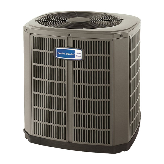
The following instructions cover 4A7A6 Condensing Units. See
special wiring and sequence of operation on page 5.
NOTICE: These outdoor units may be used with indoor
units equipped with Thermostatic Expansion Valve only.
▲
WARNING:
erant which operates at 50% to 70% higher pressures than
R-22. Use only R-410A approved service equipment. Re-
frigerant cylinders are painted a "Rose" color to indicate
the type of refrigerant and may contain a "dip" tube to
allow for charging of liquid refrigerant into the system.
All R-410A systems use a POE oil that readily absorbs
moisture from the atmosphere. To limit this "hygroscopic"
action, the system should remain sealed whenever pos-
sible. Never break a vacuum with air and always change
the driers when opening the system for component
replacement.
Check for transportation damage after unit is uncrated. Report
promptly, to the carrier, any damage found to the unit.
To determine the electrical power requirements of the unit, refer
to the nameplate of the unit. The electrical power available must
agree with that listed on the nameplate.
B. LOCATION & PREPARATION OF THE UNIT
1. When removing unit from the pallet, notice the tabs on the
basepan. Remove tabs by cutting with a sharp tool as shown in
Figure 2 (see page 2).
2. The unit should be set on a level support pad at least as large
as the unit base pan, such as a concrete slab. If this is not the
application used please refer to application bulletin
"ALG16-APG**-EN" (* denotes latest revision).
3. The support pad must NOT be in direct contact with any
structure. Unit must be positioned a minimum of 12" from any
wall or surrounding shrubbery to insure adequate airflow. Clear-
© 2005 American Standard Inc. All Rights Reserved
Condensing Units
Models:
4A7A6024,36,48, & 60B1000A
These units use R-410A refrig-
!
UNIT CONTAINS R-410A REFRIGERANT!
R-410A OPERATING PRESSURE EXCEEDS THE
LIMIT OF R-22. PROPER SERVICE EQUIPMENT IS
REQUIRED. FAILURE TO USE PROPER SERVICE
TOOLS MAY RESULT IN EQUIPMENT DAMAGE OR
PERSONAL INJURY.
SERVICE
USE ONLY R-410A REFRIGERANT AND
APPROVED POE COMPRESSOR OIL.
1
TOP DISCHARGE — UNRESTRICTED
5 FT. ABOVE UNIT
Since the manufacturer has a policy of continuous product
and product data improvement, it reserves the right to
change design and specifications without notice.
11-AC16D1-3
CAUTION
Advertisement
Table of Contents

Related Manuals for American Standard 4A7A6024


Summary of Contents for American Standard 4A7A6024
- Page 1 Clear- Since the manufacturer has a policy of continuous product and product data improvement, it reserves the right to © 2005 American Standard Inc. All Rights Reserved change design and specifications without notice.
- Page 2 INSTALLER'S GUIDE 1. Determine the most practical way to run the lines. BASEPAN TAB REMOVAL 2. Consider types of bends to be made and space limitations. NOTE: Large diameter tubing will be very difficult to rebend once it has been shaped. 3.
- Page 3 INSTALLER'S GUIDE LEAK CHECK GAS LINE SERVICE VALVE IMPORTANT: Replace pressure tap port valve core be- fore attaching hoses for evacuation. 1/4 TURN ONLY COUNTERCLOCKWISE After the brazing operation of refrigerant lines to both the FOR FULL OPEN POSITION outdoor and indoor unit is completed, the field brazed connec- tions must be checked for leaks.
- Page 4 INSTALLER'S GUIDE 12. The gas valve is now open for refrigerant flow. Replace valve H. ELECTRIC HEATERS stem cap to prevent leaks. Again, these caps MUST BE RE- Electric heaters, if used, are to be installed in the air handling PLACED to prevent leaks.
- Page 5 INSTALLER'S GUIDE FIELD HOOK-UP DIAGRAMS FOR 4A7A6 MODELS ONLY Note A Note A Notes: 1. Be sure power supply agrees with equipment nameplate. 2. Power wiring and grounding of equipment must comply with local codes. 3. Low voltage wiring to be No. 18 AWG minimum conductor. 4.
- Page 6 INSTALLER'S GUIDE 4A7A6 OUTLINE DRAWING NOTE: ALL DIMENSIONS ARE IN MM (INCHES). MODELS BASE 4A7A6024B 933 (36-3/4) 829 (32-5/8) 756 (29-3/4) 5/8 5/16 143 (5-5/8) 92 (3-5/8) 210 (8-1/4) 79 (3-1/8) 508 (20) 4A7A6036B 841 (33-1/8)) 946 (37-1/4) 870 (34-1/4) 3/4 3/8 152 (6) 98 (3-7/8) 219 (8-5/8) 86 (3-3/8)
- Page 7 INSTALLER'S GUIDE MOUNTING HOLE LOCATION NOTE: ALL DIMENSIONS ARE IN MM (INCHES). NOTE: For model base size, see table on page 6. From Dwg. 21D152989 Rev. 0 Pub. No. 11-AC16D1-3 PAGE 7...
- Page 8 2 Check only necessary if heating unit is used for indoor section and wiring has been disturbed during installation of cooling equipment. 3 When applicable. Technical Literature - Printed in U.S.A. American Standard Inc. Troup Highway Tyler, TX 75707-9010 PAGE 8 Pub.
Need help?
Do you have a question about the 4A7A6024 and is the answer not in the manual?
Questions and answers