Advertisement
Quick Links
ALL phases of this installation must comply with NATIONAL, STATE AND LOCAL CODES
IMPORTANT — This Document is customer property and is to remain with this unit. Please return to service
information pack upon completion of work.
These instructions do not cover all variations in systems or provide for every possible contingency to be met in connection with
the installation. Should further information be desired or should particular problems arise which are not covered sufficiently for the
purchaser's purposes, the matter should be referred to your installing dealer or local distributor.
Note: The manufacturer recommends installing only approved matched indoor and outdoor systems. All of the manufacture's split
systems are AHRI rated only with TXV/EEV indoor systems. Some of the benefits of installing approved matched indoor and out-
door split systems are maximum efficiency, optimum performance and the best overall system reliability.
Table of Contents
Section 1. Safety ..................................................................................... 2
Section 2. Unit Location Considerations.............................................. 3
Section 3. Unit Preparation .................................................................... 4
Section 4. Setting the Unit ..................................................................... 4
Section 5. Refrigerant Line Considerations ......................................... 4
Section 6. Refrigerant Line Routing ..................................................... 6
Section 7. Refrigerant Line Brazing ...................................................... 7
Section 8. Refrigerant Line Leak Check ............................................... 8
Section 9. Evacuation ............................................................................. 8
Section 10. Service Valves ..................................................................... 8
Section 11. Electrical - Low Voltage ..................................................... 9
Section 12. Electrical - High Voltage .................................................. 11
Section 13. Start Up .............................................................................. 11
Section 14. System Charge Adjustment ............................................. 11
Section 15. Checkout Procedures ....................................................... 15
Section 16. Refrigerant Circuits .......................................................... 16
Section 17. Wiring Diagrams ............................................................... 17
Section 18. Pressure Curves ............................................................... 20
Installation and Operation Manual
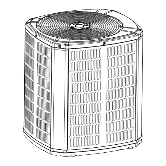
Condensing Units
4A7C7
11-AC38D1-1D-EN
Advertisement

Related Manuals for American Standard 4A7C7


Summary of Contents for American Standard 4A7C7
- Page 1 11-AC38D1-1D-EN Installation and Operation Manual Condensing Units 4A7C7 ALL phases of this installation must comply with NATIONAL, STATE AND LOCAL CODES IMPORTANT — This Document is customer property and is to remain with this unit. Please return to service information pack upon completion of work.
- Page 2 Section 1. Safety LIVE ELECTRICAL COMPONENTS! This information is intended for use by individuals During installation, testing, servicing, and trouble- possessing adequate backgrounds of electrical and shooting of this product, it may be necessary to work mechanical experience. Any attempt to repair a central with live electrical components.
- Page 3 Section 2. Unit Location Considerations 2.1 Unit Dimensions and Weight Table 2.1 Unit Dimensions and Weight Models H x D x W (in) Weight* (lb) 4A7C7036A3/4 45 x 34 x 37 4A7C7048A3/4 45 x 34 x 37 4A7C7060A3/4 45 x 34 x 37 * Weight values are estimated.
- Page 4 2.4 Cold Climate Considerations NOTE: It is recommended that these precautions be taken for units being installed in areas where snow accu- mulation and prolonged below freezing temperatures occur. • Units should be elevated 3-12 inches above the pad or roof top, depending on local weather. This additional height will allow drainage of snow and ice melted during defrost cycle prior to its refreezing.
- Page 5 Line Sizes Service Valve Connection Sizes Max Line & Lift Lengths ALTERNATE LINE SIZES Vapor Liquid Vapor Line Liquid Line TOTAL Max Max Lift (ft.) Line Line Connection Connection Line Length (ft.) 4A7C7036A3/4 4A7C7048A3/4 4A7C7060A3/4 Note: For other line lengths, Refer to Refrigerant Piping Application Guide, SS-APG006-EN or Refrigerant Piping Software Program, 32-3312-xx (latest revision).
- Page 6 Section 6. Refrigerant Line Routing 6.1 Precautions Important: Take precautions to prevent noise Comply with National, State, and Local Codes when within the building structure due to vibration isolating line sets from joists, rafters, walls, or other transmission from the refrigerant lines. structural elements.
- Page 7 Wall Sealant Ductwork Insulation Vapor Line Isolator Line Set Isolation Through Wall DO NOT hang line sets from ductwork Section 7. Refrigerant Line Brazing 7.1 Braze The Refrigerant Lines STEP 1 - Remove caps or plugs. Use a deburing tool to debur the pipe ends. Clean both internal and external surfaces of the tubing using an emery cloth.
- Page 8 Section 8. Refrigerant Line Leak Check 8.1 Check For Leaks STEP 1 - Pressurize the refrigerant lines and evaporator coil to 150 PSIG using dry nitrogen. STEP 2 - Check for leaks by using a soapy solution or bubbles at each brazed location. Remove nitrogren pressure and repair any leaks before continuing.
- Page 9 1/4 TURN ONLY COUNTERCLOCKWISE FOR FULL OPEN Unit Side POSITION of Service 3/16” Hex Wrench Valve Rolled Edge to VALVE STEM Captivate Stem Hex Headed UNIT SIDE Valve System OF VALVE PRESSURE TAP PORT Service Port GAS LINE CONNECTION Gas Service Valve Liquid Service Valve Section 11.
- Page 10 With Variable Speed UH2/DH2-V Furnace Outdoor Thermostat Furnace Unit • Units with pigtails require wirenuts for connec- tions. Cap all unused wires. 24 VAC HOT • In systems with multiple stages of heat, jumper W1 and W2 together if comfort control has only one stage of heat.
- Page 11 Section 12. Electrical - High Voltage 12.1 High Voltage Power Supply LIVE ELECTRICAL COMPONENTS! During installation, testing, servicing, and troubleshooting of this product, it may be nec- essary to work with live electrical components. Failure to follow all electrical safety precau- tions when exposed to live electrical compo- nents could result in death or serious injury.
- Page 12 14.2 Subcooling Charging in Cooling (Above 55º F Outdoor Temp.) STEP 1 - Use the refrigerant line total length and lift measurements from Section 5.3. Total Line Length = __________ Ft. LIFT Vertical Change (Lift) = __________ Ft. STEP 2 - Determine the final subcooling value using total Line Length and Lift measured in STEP 1 and the charts below. 2 Ton Heat AC 3 Ton Heat AC SUBCOOL CHARGING CHART CORRECTIONS TABLE (FOR LINE LENGTH AND RISE)
- Page 13 Table 14.2 R-410A REFRIGERANT CHARGING CHART FINAL SUBCOOLING ( ° LIQUID TEMP LIQUID GAGE PRESSURE (PSI) ° 179 182 185 188 191 195 198 195 198 201 204 208 211 215 107 °F 211 215 218 222 225 229 232 229 232 236 240 243 247 251 247 251 255 259 263 267 271 267 271 275 279 283 287 291...
- Page 14 STEP 9 - Record System Information for refer- ence. Record system pressures and temperatures after charging is complete. Outdoor model number = _________________ Measured Suction Line Temp = __________ º F Liquid Gage Pressure = __________ PSIG Measured Outdoor Ambient = __________ º F Suction Gage Pressure = __________ PSIG Measured Indoor Ambient = __________ º...
- Page 15 STEP 2 - Stabilize the system by operating for a minimum of 20 minutes. At startup, or whenever charge is removed or added, the system must be operated for a minimum of 20 minutes to stabilize before accurate measurements can be made. STEP 3 - Check the liquid line temperature and liquid gage pressure to obtain a minimum of 10º...
- Page 16 Section 16. Refrigerant Circuits 3-Ton Units Cooling Refrigeration Cycle Printed from D156597 Rev00 4 & 5-Ton Units L I N E D A M P E N E R ( S E E N O T E 1 ) PRINTED FROM D156708 11-AC38D1-1D-EN...
- Page 17 Section 17. Wiring Diagrams 11-AC38D1-1D-EN...
- Page 18 11-AC38D1-1D-EN...
- Page 19 11-AC38D1-1D-EN...
- Page 20 Section 18. Pressure Curves COOLING PERFORMANCE CAN BE CHECKED WHEN THE OUTDOOR TEMP IS ABOVE 65 DEG F. TO CHECK COOLING PERFORMANCE, SELECT THE PROPER INDOOR CFM, ALLOW PRESSURES TO STABILIZE. MEASURE INDOOR WET BULB TEMPERATURE, OUTDOOR TEMPERATURE, LIQUID AND SUCTION PRESSURES. ON THE PLOTS LOCATE OUTDOOR TEMPERATURE (1); LOCATE INDOOR WET BULB (2);...
- Page 21 PRESSURE CURVES FOR 4A7C7036A4 Cooling with Thermal Expansion Valve Cooling with Thermal Expansion Valve INDOOR ENTERING INDOOR ENTERING WET BULB CURVES WET BULB CURVES TOP TO BOTTOM 71, TOP TO BOTTOM 71, 67, 63 AND 59 DEG F. 67, 63 AND 59 DEG F. 110 120 OUTDOOR TEMPERATURE (Degree F) INDOOR ENTERING...
- Page 22 PRESSURE CURVES FOR 4A7C7048A4 Cooling with Thermal Expansion Valve Cooling with Thermal Expansion Valve INDOOR ENTERING INDOOR ENTERING WET BULB CURVES WET BULB CURVES TOP TO BOTTOM 71, TOP TO BOTTOM 71, 67, 63 AND 59 DEG F. 67, 63 AND 59 DEG F. OUTDOOR TEMPERATURE (Degree F) INDOOR ENTERING INDOOR ENTERING...
- Page 23 PRESSURE CURVES FOR 4A7C7060A4 Cooling with Thermal Expansion Valve Cooling with Thermal Expansion Valve INDOOR ENTERING INDOOR ENTERING WET BULB CURVES WET BULB CURVES TOP TO BOTTOM 71, TOP TO BOTTOM 71, 67, 63 AND 59 DEG F. 67, 63 AND 59 DEG F. 110 120 OUTDOOR TEMPERATURE (Degree F) INDOOR ENTERING...
- Page 24 About American Standard Heating and Air Conditioning American Standard has been creating comfortable and affordable living environments for more than a century. For more information, please visit www.americanstandardair.com. The AHRI Certified mark indicates company participation in the AHRI Certification program. For verification of individual certified products, go to ahridirectory.org.
Need help?
Do you have a question about the 4A7C7 and is the answer not in the manual?
Questions and answers