Advertisement
Quick Links
Advertisement

Related Manuals for Mitsubishi Electric MAC-587-IF


Summary of Contents for Mitsubishi Electric MAC-587-IF
- Page 1 Wi-Fi INTERFACE MAC-567IF-E Model INSTALLATION MANUAL English(GB)
-
Page 2: Table Of Contents
Improper connection and mounting may result Incomplete connecting or mounting may result in breakdown, heat generation, smoke genera- in broken wire, heat generation, smoke genera- tion, or fire. tion, or fire. ■ Mitsubishi Electric’s components or other ■ Do not install the Wi-Fi interface nearby the designated components must be used for automatic control devices such as auto- installation. matic doors or fire alarms. Improper component may result in fire, electric It can cause accidents due to malfunctions. - Page 3 Warning (Improper handling may have serious consequences, including serious injury or death.) ■ Do not use the Wi-Fi interface nearby the ■ This equipment should be installed and medical electrical equipment or people who operated with a minimum distance of 20 have a medical device such as a cardiac cm between the device and the user or pacemaker or an implantable cardioverter- bystanders.
- Page 4 [Precautions for setting up, or use of the Wi-Fi interface] ■ Meanings of symbols used in this manual Be sure not to do. Be sure to follow the instruction. Never touch with wet hand. Be sure to disconnect the power supply plug from the power outlet. Never splash water on the unit. Warning (Improper handling may have serious consequences, including serious injury or death.) ■ Do not disassemble, modify, or repair ■ Do not touch the Wi-Fi interface with by yourself (user). wet hands. It can cause electric shock, fire, or injury.
- Page 5 ■ The End user should read and accept the terms ■ This Wi-Fi interface should not be installed and and conditions of the Wi-Fi service before connected to any Mitsubishi Electric system commencement of the installation of this Wi-Fi which is to provide application critical cooling interface. or heating. ■ To complete connection of this Wi-Fi inter- ■ Please write down the model information and face to the Wi-Fi service the Router may be more on the last page "Setting information", required. when you install this Wi-Fi interface. Mitsubishi Electric’s Wi-Fi Interface is designed for communication to Mitsubishi Electric’s MELCloud Wi-Fi service. Third party Wi-Fi interfaces cannot be connected to MELCloud. Mitsubishi Electric is not responsible for any (i) underperformance of a system or any product; (ii) system or product fault; or (iii) loss or damage to any system or product; which is caused by or arises from connection to and/or use of any third party Wi-Fi interface or any third party Wi-Fi service with Mitsubishi Electric equipment. For the latest information regarding MELCloud from Mitsubishi Electric Corporation, please visit GB-4...
-
Page 6: Product Introduction
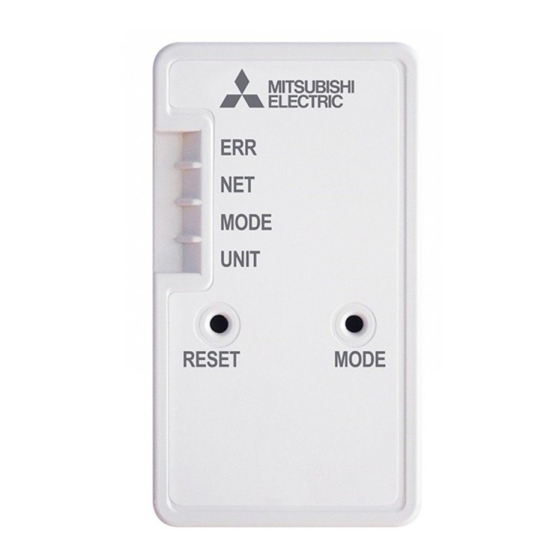
2. Product Introduction Item Description MODE switch It selects modes. RESET switch It resets the system and ALL settings. MODE ERR LED (Orange) It shows the network error state. UNIT NET LED (Green) It shows the network state. RESET MODE MODE LED (Orange) It shows the Access point mode state. UNIT LED (Green) It shows the indoor unit state. (1) MODE switch ● The MODE switch is used for selecting modes in configurations. (2) RESET switch ● Hold down the RESET switch for 2 seconds to reboot the system. ● Hold down the RESET switch for 14 seconds to initialize the Wi-Fi interface to the factory default. When the Wi-Fi interface is reset to the factory default, ALL the configuration information will be lost. -
Page 7: Connecting The Wi-Fi Interface
4. Connecting the Wi-Fi interface (For details on each system, see the relevant instruction manual.) Turn off the breaker of the room airconditioner or the ATW unit before connecting the cable to the indoor unit. Refer to the installation manual of each model for connecting instructions and details. (1) The connecting cable connected to a indoor unit (CN105) should be mounted at the indoor unit or its vicinity. When mounting the Interface unit inside an indoor unit, refer to the installation manual of the indoor unit. Do not mount the Interface unit inside the indoor unit, if not mentioned. - Page 8 When mounting on the outer side of indoor unit • Insert the clip into the holder until it clicks. • Insert the interface unit into the holder until it clicks. Note: When inserting the interface unit into the holder, align the cable of the Interface unit with the mark for the cable on the holder . Otherwise, light leakage or degradation in appearance may result. Holder Holder Mark for cable Align Interface unit Clip Connecting cable • Slip the clip over the edge of corner box to fix the interface unit . Note: Mount the interface unit on the underside of the indoor unit if it cannot be mounted on the side of the indoor unit.
-
Page 9: Specifications
<ATW indoor unit> Cylinder unit Hydrobox Connecting to Cylinder unit Connecting to Hydrobox Mounting cord clamp 4 Screw 3 Screw 3 Mounting cord clamp 4 Mount in the same procedure for room air conditioner. Please refer to “When mounting on the wall” on page 6. Initial State (2) Turn on the breaker of the room air conditioner or the ATW unit and check that the LED indication of the Wi-Fi interface enters the initial state shown on right. MODE OFF UNIT Flashing Setting up Refer to SETUP QUICK REFERENCE GUIDE (Included in same package) and SETUP MANUAL to connect to a Router for setting up. For SETUP MANUAL, please go to the website below. For MELCloud User Manual, please go to the website below. 5. Specifications Input Voltage DC12.7 V (from indoor unit) Power consumption MAX 2 W Size H×W×D (mm) 79×44×18.5 Weight (g) 110 (including cable) Transmitter power level (MAX) 17.5 dBm @IEEE 802.11b... - Page 10 Setting information Indoor unit model name Indoor unit serial number Outdoor unit model name Outdoor unit serial number Wi-Fi interface MAC address (MAC) Wi-Fi interface serial number (ID) Wi-Fi interface PIN (PIN) Wi-Fi interface SSID (SSID) Wi-Fi Interface KEY (KEY) System commissioning date Wi-Fi interface installation date Installer contact details...
- Page 11 Travellers Lane, Hatfield, Herts., AL10 8XB, England, U.K. Polish Branch Krakowska 50, PL-32-083 Balice, Poland MITSUBISHI ELECTRIC TURKEY ELEKTRİK ÜRÜNLERI A.Ş. Şerifali Mah. Kale Sok. No: 41 34775 Ümraniye, İstanbul / Turkey MITSUBISHI ELECTRIC (RUSSIA) LLC 52, bld.1 Kosmodamianskaya Nab. 115054, Moscow, Russia...
- Page 12 This product is designed and intended for use in the residential, commercial and light-industrial environment. HEAD OFFICE: TOKYO BUILDING, 2-7-3, MARUNOUCHI, CHIYODA-KU, TOKYO 100-8310, JAPAN MITSUBISHI ELECTRIC CONSUMER PRODUCTS (THAILAND) CO., LTD AMATA NAKORN INDUSTRIAL ESTATE 700/406 MOO 7, TAMBON DON HUA ROH, AMPHUR MUANG, CHONBURI 20000, THAILAND...
Need help?
Do you have a question about the MAC-587-IF and is the answer not in the manual?
Questions and answers