Mitsubishi Electric MAC-567IF-E Installation Manual
Hide thumbs
Also See for MAC-567IF-E:
- Installation manual (21 pages) ,
- Setup manual (137 pages) ,
- Setup manual (10 pages)
Advertisement
L L
7 5
RGHO
67
7
67
7
6
67
67
7
67
67
67
7
6
67
7
6
67
5
6 c
6
6
6
INSTRUKCJA MONTAŻU
7
7e6
e
PŘÍRUČKA PRO INSTALACI
РЪКОВОДСТВО ЗА МОНТАЖ
РУКОВОДСТВО ПО УСТАНОВКЕ
67
ΕΓΧΕΙΡΙΔΙΟ ΟΔΗΓΙΩΝ ΕΓΚΑΤΑΣΤΑΣΗΣ
MONTAJ ELKİTABI
ПОСІБНИК ІЗ МОНТАЖУ
7
d
g
(
OLVK
H WVFK
)UD oDLV )
HGHUOD GV
(VSD RO (
RUW
rV
D VN
(
YH VND
:
RUVN
RPL )
ROVNL
D
DU
Český (CZ)
Български
Русский
WDOLD R
Ελληνικά
UNoH .
Українська
.
Advertisement
Table of Contents

Related Manuals for Mitsubishi Electric MAC-567IF-E


Summary of Contents for Mitsubishi Electric MAC-567IF-E
- Page 1 RGHO OLVK H WVFK )UD oDLV ) HGHUOD GV (VSD RO ( D VN YH VND RUVN RPL ) INSTRUKCJA MONTAŻU ROVNL PŘÍRUČKA PRO INSTALACI Český (CZ) Български РЪКОВОДСТВО ЗА МОНТАЖ Русский РУКОВОДСТВО ПО УСТАНОВКЕ WDOLD R Ελληνικά ΕΓΧΕΙΡΙΔΙΟ ΟΔΗΓΙΩΝ ΕΓΚΑΤΑΣΤΑΣΗΣ MONTAJ ELKİTABI UNoH .
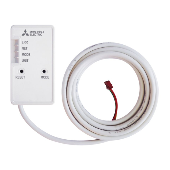
- Page 2 R WH W 1. Safety precautions..................2. Product Introduction ..................3. Parts ....................... 4. Connecting the Wi-Fi interface ............... 5. Speci cations ....................ER W :L )L L WH IDFH This Wi-Fi interface, communicates the status information and controls the commands from the MELCloud by connecting to an indoor unit.
- Page 3 :D L (Improper handling may have serious consequences, including serious injury or death.) ■ R RW H W H :L )L L WH IDFH HD E W H ■ L HT LSPH W R O EH L WDOOH D PH LFDO HOHFW LFDO HT LSPH W R SHRSOH RSH DWH LW D PL LP P L WD FH RI D H D PH LFDO H LFH...
- Page 4 3 HFD WLR HWWL H RI W H :L )L L WH IDFH ■ Meanings of symbols used in this manual Be sure not to do. Be sure to follow the instruction. Never touch with wet hand. Be sure to disconnect the power supply plug from the power outlet.
- Page 5 Third party Wi-Fi interfaces cannot be connected to MELCloud. Mitsubishi Electric is not responsible for any (i) underperformance of a system or any product; (ii) system or product fault; or (iii) loss or damage to any system or product; which is caused by or arises from connection to and/or use of any third party Wi-Fi interface or any third party Wi-Fi service with Mitsubishi Electric equipment.
- Page 6 FW , W R FWLR Item Description MODE switch It selects modes. RESET switch It resets the system and ALL settings. MODE UNIT ERR LED (Orange) It shows the network error state. NET LED (Green) It shows the network state. RESET MODE MODE LED (Orange) It shows the Access point mode state.
- Page 7 HFWL W H :L )L L WH IDFH HWDLO R HDF HH W H HOH D W L W FWLR PD Turn off the breaker of the room airconditioner or the ATW unit before connecting the cable to the indoor unit. Refer to the installation manual of each model for connecting instructions and details.
- Page 8 When mounting on the outer side of indoor unit • Insert the clip into the holder until it clicks. • Insert the interface unit into the holder until it clicks. Note: When inserting the interface unit into the holder, align the cable of the Interface unit with the mark for the cable on the holder Otherwise, light leakage or degradation in appearance may result.
Need help?
Do you have a question about the MAC-567IF-E and is the answer not in the manual?
Questions and answers