Table of Contents
Advertisement
Quick Links
Bedienungsanleitung
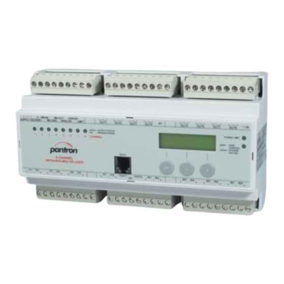
8-Kanal Lichtschrankenverstärker
ISM-8800
Sicherheitshinweise am Ende dieser Anleitung beachten!
Einleitung
Die Lichtschrankenverstärker werden zur Erkennung von Objekten in Maschinen oder Produktionsanlagen
eingesetzt. Sie bilden in Verbindung mit Infrarotsendern IT... und Infrarotempfängern IR... (nicht
im Lieferumfang) eine leistungsstarke Lichtschranke und sind einsetzbar in Bereichen mit hoher
Reichweite oder Verschmutzung. Sie können als Einweg-Lichtschranke, Reflektions-Lichttaster oder
Reflektions-Lichtschranke betrieben werden.
Arbeitsweise
Das ISM-8800 ist ein 8-Kanal Lichtschranken-Verstärker, dessen Verstärkung zwischen manueller
und automatischer Einstellung wählbar ist.
Der Verstärker arbeitet mit moduliertem Infrarotlicht, wodurch eine hohe Sicherheit gegen Fremdlicht
erreicht wird. Die Schaltung ist so ausgelegt, daß nur Signale richtiger Frequenz und Phasenlage
erkannt werden. Dadurch ist eine Beeinflussung durch andere Lichtschranken nahezu ausgeschlossen.
Ein Analogausgang liefert eine Gleichspannung von 0 ... 10 V DC in Abhängigkeit von der Streckenqualität
zwecks Ausrichtung der Sensoren oder Trübungsmessung.
Installation
Der Verstärker darf senkrecht und waagerecht auf eine Tragschiene (EN 60715) montiert werden.
Geräte, die schädliche Wärme abgeben, sind in einem Abstand von min. 20 mm zu platzieren
(Betriebstemperatur: 0° C ... +50° C). Für den Anschluss der Steckverbinder ist oben und unten ein
Abstand von mindestens 15 mm zu anderen Teilen einzuhalten. Die Betriebsspannung des Verstärkers
beträgt 24 V DC ± 20 %.
Anschlussschema / Wiring diagram
Master-Slave
vorheriges
Betriebsspannung
Erde
Gerät
Supply voltage
Ground
previous
device
Master
24V DC
MS-
MS-
OUT
GND
1
2
3
4
5
MS-IN
24 V DC
MS-GND
IT1
IT2
IT3
28
29
30
31
32
● Betriebsspannung
Die Versorgungsspannung für das ISM-8800
beträgt 24 V DC. Die Spannung wird an die
Anschlüsse Pin 1 (+) und Pin 2 (-) angeklemmt.
Gegen Verpolung ist das Gerät intern geschützt.
● Erde
Der Anschluss (Pin 3) verbindet das Gerät mit
Nullpotential der Umgebung.
● Sender
Die maximal 8 IR-Sender werden über Pin 28
(+) und Pin 29 (-) bis Pin 39 (+) und Pin 38 (-)
angeschlossen. Auf die Polung ist zu achten. Die
Anschlüsse sind kurzschlussfest.
● Empfänger
Die maximal 8 IR-Empfänger werden über Pin
43 (+) und Pin 44 (-) bis Pin 54 (+) und Pin 53
(-) angeschlossen. Auf die Polung ist zu achten.
Die Anschlüsse sind kurzschlussfest.
● Schaltausgänge
An die Schaltausgänge Pin 10...17, 19...26
(potentialfreie Halbleiter-Relais) lassen sich Lasten
mit max. 60 V AC (DC) / 100 mA anschließen, um
Lichtschranken-Ereignisse auswerten zu können.
Die Relais sind kurzschlussfest.
● Testeingang 1
Der Testeingang 1 (Pin 40) bietet die Möglichkeit
die Funktion des Lichtschrankensystem zu prüfen.
Legt man an den Eingang eine Spannung von 24
V DC an, schalten sich die Sender elektronisch ab
und ein Zustandswechsel an den Schaltausgängen
erfolgt.
OI140311DE/EN
Ausgang
Output
folgendes
Analogausgang
Gerät
Error
Limit
succeed
24 V / 100 mA
device
Slave
MS-
MS-
Last
Last
GND
IN
Load
Load
6
7
8
9
10
MS-OUT
ERROR
ANALOG
LIMIT
IT4
IT5
IT6
33
34
35
36
37
8
7
6
5
4
3
2
1
Sender
Transmitter
● Testeingang 2
Testeingang 2 (Pin 41) besitzt die gleiche Funktion
wie Testeingang 1, ist aber nur in Verbindung mit
der Lichtvorhang-Funktion aktiv.
● Analogausgang
Am Analogausgang ist eine Spannung zwischen 0
und 10 V abnehmbar, die von der Streckenqualität
der Lichtschranke abhängt und dient z. B. zum
Ausrichten der Sensoren mittels Voltmeter.
● Errorausgang
Der Errorausgang Pin 8 ist bei einem Sensorfehler
oder Systemfehler des Geräts aktiv. Der High-
Side-Ausgang ist kurzschlussfest.
● Limitausgang
Der Limitausgang Pin 9 ist aktiv, wenn die
Leistungsgrenze erreicht ist oder die automatische
Leistungsregelung aussetzt. Der High-Side-
Ausgang ist kurzschlussfest.
● Master - Slave
Über die Anschlüsse Pin 4, 5 (GND) und 6 lassen
sich ISM-Multiplexer synchronisieren, sodass
weitere Lichtschranken im Multiplexverfahren
bedient werden können.
● COM-Schnittstelle
Das Gerät ISM-8800 besitzt eine integrierte
serielle Schnittstelle. Mit optional erhältlichem
Verbindungskabel (Typ CAB-COM-2m) zur COM-
Schnittstelle des PC und der Software WinISM ist
eine komfortable Bedienung des Lichtschranken-
Systems möglich.
Alle technischen Angaben beziehen sich auf den Stand 12/2015. Änderungen bleiben vorbehalten.
All technical specifications refer to the state of the art 12/2015. They are subject to modifications.
Operating Instructions
8-channel light barrier amplifier
ISM-8800
Introduction
The light barrier amplifiers are used for the detection of objects in machines or production systems.
They form, in conjunction with infrared transmitters and receivers (not included in delivery), a powerful
light barrier and they are useable in areas with long range or an extreme degree of pollution. They
can operate as Trough Beam, Retro-Reflective or Diffuse Proximity.
Principle of operation
The ISM-8800 is an 8-channel amplifier with change-over gain setting mode between manual and
automatic mode.
This amplifier works with modulated infrared light, which provides high immunity to ambient light. The
electronic circuit is designed to detect only those signals with the correct frequency and phase relation.
This almost completely excludes interference from other light barriers.
An analog output, which supplies a voltage between 0 ... 10 V DC independent of the received power,
is useable to adjust the sensor heads or measure the turbidness of the environment.
Installation
It is acceptable to mount the amplifier using a DIN rail (EN 60715) vertically or horizontally. Devices
that release dangerous heat must be mounted at a distance of at least 20 mm (operation temperature:
0°C (32°F) ... +50°C (+122°F). For electrical connection a distance of at least 15 mm from top and
bottom of the device to other parts is needed. The supply voltage of the device is 24 V DC ± 20 %.
Schaltausgang Kanal 1-4
Switching output channel 1-4
60 V / 100 mA
3
1
2
4
Last
Last
Last
Last
Load
Load
Load
Load
11
12
13
14
15
16
17
18
NC
OUT1
OUT2
OUT3
OUT4
IT7
IT8
IR1
IR2
TEST1
TEST2
38
39
40
41
42
43
44
45
8
Testeingang
7
6
24 V DC / 2 mA
5
4
3
2
1
● Supply voltage
The supply voltage for the ISM-8800 amplifier is
about 24 V DC ± 20 % at Pin 1 (+) and Pin 2 (-).
The device is protected against inverse-polarity.
● Earth
This pin (No. 3) connects the device with ground
of the environment.
● Transmitter
The maximum eight IR-Transmitter, connect from
Pin 28 (+) and 29 (-) to Pin 39 (+) and 38 (-). The
transmitter connections are short-circuit proof.
● Receiver
The maximum eight IR-Receiver, are connecting
at Pin 43 (+) and 44 (-) to Pin 54 (+) and 53 (-).
The receiver connections are short-circuit proof.
● Switching output
The switching outputs Pin 10...17, 19...26 are
allowed, to drive loads of about 60 V AC (DC) /
100 mA. The semiconductor relays are floating
and short-circuit proof.
● Test input 1
The test input 1 (Pin 40) offers the practicability
to check the photo-electric system. By connecting
a voltage of about 24 V DC at this input, all
transmitters switch off and the state of the
outputs change.
Regard the security notes at the end of this manual!
Schaltausgang Kanal 5-8
Switching output channel 5-8
60 V / 100 mA
5
6
Last
Last
Load
Load
19
20
21
22
23
OUT5
OUT6
IR3
IR4
IR5
46
47
48
49
50
Empfänger
Receiver
● Test input 2
Test input 2 (Pin 41) is only active, during light
Curtain Mode, and has then the same function as
Test input 1, but only for a part of the transmitters.
● Analog output
At the Analog output (Pin 7) a voltage between 0
and 10 V is available, depending upon the beam
quality. The application of this function is to adjust
the sensor heads by voltmeter for example.
● Error output
At Pin 8 (error output) a voltage is available, when
a Sensor Error or System Error is present. The
High-Side output is short-circuit proof.
● Limit output
At Pin 9 (limit output) a voltage is available, when
the limit of capacity is reached. The High-Side
output is short-circuit proof.
● Master - Slave
With these connections Pin 4, 5 (GND) and 6,
several ISM multiplexers can synchronized. So
it is possible to operate with more channels.
● COM interface
The ISM-8800 is provided with a serial interface.
With optional available communication cable
(type CAB-COM-2m) linked to the COM-Interface
of a PC and the software WinISM, easy operation
by PC is possible.
7
8
Last
Last
Load
Load
24
25
26
27
NC
OUT7
OUT8
IR6
IR7
IR8
51
52
53
54
1
/6
Advertisement
Table of Contents

Related Manuals for Pantron ISM-8800


Summary of Contents for Pantron ISM-8800
- Page 1 Arbeitsweise Principle of operation Das ISM-8800 ist ein 8-Kanal Lichtschranken-Verstärker, dessen Verstärkung zwischen manueller The ISM-8800 is an 8-channel amplifier with change-over gain setting mode between manual and und automatischer Einstellung wählbar ist. automatic mode. Der Verstärker arbeitet mit moduliertem Infrarotlicht, wodurch eine hohe Sicherheit gegen Fremdlicht This amplifier works with modulated infrared light, which provides high immunity to ambient light.
- Page 2 ● General setting in the second line. Betrieb wird Alarm dann ausgelöst, wenn für eine Die 8-Kanal Lichtschranke ISM-8800 lässt sich This device works with modulated IR-light, so that The alarm is active, when the received signal is bestimmte Zeitspanne das Empfangssignal zu am Gerät durch eine menügeführte Bedienung,...
- Page 3 Bedienungsanleitung Operating Instructions 8-Kanal Lichtschrankenverstärker 8-channel light barrier amplifier ISM-8800 ISM-8800 ● CHANNEL SETTINGS (Kanaleinstellungen) Wählen Sie im Automatik- ● CHANNEL SETTINGS ○ Channel disconnection (OFF) Wählen Sie im Hauptmenü CHANNEL SETTINGS B e t r i e b m i t d e n Select CHANNEL SETTINGS in the main menu and und drücken Sie...
- Page 4 Bedienungsanleitung Operating Instructions 8-Kanal Lichtschrankenverstärker 8-channel light barrier amplifier ISM-8800 ISM-8800 ● CURTAIN MODE (Lichtvorhang) ● MASTER MODE ● ANALOG OUTPUT Press button to change to the sensor Mit der Master-Slave- display or to another channel. The output voltage is for simple measure Wählen Sie CURTAIN...
- Page 5 Bedienungsanleitung Operating Instructions 8-Kanal Lichtschrankenverstärker 8-channel light barrier amplifier ISM-8800 ISM-8800 ● SYSTEM INFO ● Problembehebung ● TEST INPUT Wählen Sie im Hauptmenü den Punkt SYSTEM With the test input, a test of the device function is INFO und drücken Sie possible by external test equipment.
- Page 6 Operating temperature Lagerungstemperatur -10 °C ... +60 °C (14 °F ... +140 °F) Storage temperature Prüfungen Approvals Tel. +49 (0) 5063 / 9591-0 Pantron Instruments GmbH +49 (0) 5063 / 9591-55 Süllbergstraße 3-5 E-mail sales@pantron.de D-31162 Bad Salzdetfurth Internet www.pantron.de...
Need help?
Do you have a question about the ISM-8800 and is the answer not in the manual?
Questions and answers