Table of Contents
Advertisement
IMPORTANT SAFETY NOTICE
The information in this service guide is intended for use by individuals possessing adequate backgrounds of
electrical, electronic, and mechanical experience. Any attempt to repair a major appliance may result in personal
injury and property damage. The manufacturer or seller cannot be responsible for the interpretation of this
information, nor can it assume any liability in connection with its use.
WARNING
To avoid personal injury, disconnect power before servicing this product. If electrical power is required for diagnosis
or test purposes, disconnect the power immediately after performing the necessary checks.
RECONNECT ALL GROUNDING DEVICES
If grounding wires, screws, straps, clips, nuts, or washers used to complete a path to ground are removed for
service, they must be returned to their original position and properly fastened.
A
LL RIGHTS RESERVED
WRITTEN PERMISSION FROM THE MIDEA DISHWASHER MANUFACTURING
CONTENTS
Introduction ............................................................................................................................................................. 3
Specification ........................................................................................................................................................... 3
Control Panel Features ......................................................................................................................................... 3
Component Locator Views ................................................................................................................................... 4
Dishwasher Components ..................................................................................................................................... 5
Main control board ......................................................................................................................................... 6
Floater assembly ........................................................................................................................................... 7
Heating pump motor assembly .................................................................................................................... 7
Heating pump assembly ............................................................................................................................... 8
Motor assembly .............................................................................................................................................. 9
Drain pump assembly ................................................................................................................................. 10
Check plate ................................................................................................................................................... 11
Inlet valve ...................................................................................................................................................... 11
Control panel ................................................................................................................................................ 12
Technical Service Guide
Compact Dishwasher (6 settings)
MODEL SERIES:
MIDEA C
T
ECHNICAL
. T
HIS SERVICE GUIDE MAY NOT BE REPRODUCED IN WHOLE OR IN PART
WQP6-3602E
P
ONSUMER
RODUCTS
S
G
ERVICE
UIDE
COPYRIGHT. 2014
1
,
,
IN ANY FORM
WITHOUT
C
.
OMPANY
Advertisement
Table of Contents

Related Manuals for Midea WQP6-3602E Series


Summary of Contents for Midea WQP6-3602E Series
-
Page 1: Table Of Contents
COPYRIGHT. 2014 LL RIGHTS RESERVED HIS SERVICE GUIDE MAY NOT BE REPRODUCED IN WHOLE OR IN PART IN ANY FORM WITHOUT WRITTEN PERMISSION FROM THE MIDEA DISHWASHER MANUFACTURING OMPANY CONTENTS Introduction ................................3 Specification ................................3 Control Panel Features ............................3 Component Locator Views ........................... - Page 2 Operating board ............................13 Outer Door ..............................13 Dispenser ..............................14 Inner Door ..............................14 Shell ................................15 Door lock assembly ............................. 16 Air breaker ..............................16 Hinge assembly and spring system ......................17 Tank assembly ............................. 18 Troubleshooting ..............................19...
-
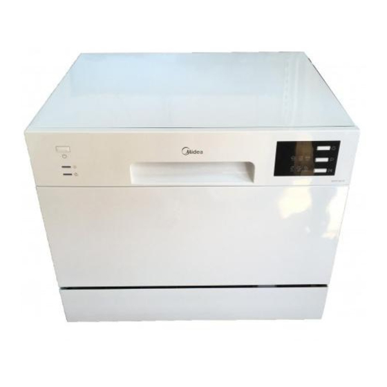
Page 3: Introduction
Introduction WQP6-3602 compact electrical dishwasher with 6 washing cycles offers good washing performance to satisfy every washing requirement. Its electronic control is easy and convenient to operate. The rack can hold up to 6 sets of dishes. The size (width * depth * height: 550mm * 500mm * 438mm) can easily fit in any corner of the kitchen, and it’s recommended to locate at which the water hose connection is accessible. -
Page 4: Component Locator Views
Component Locator Views Front View Part Name:1 – control panel 2 – outer door 3 – kick board Interior View (with basket) Part Name: 1 – cutlery basket 2 – basket 3 – dispenser 4 – inner door... -
Page 5: Dishwasher Components
Interior View (With Basket Removed) Part Name: 1 –Nut of air breaker 2 –Water Softener cover 3 –Sprayer 4 –Filter System Back View Part Name: 1 –Bottom board 2 –Power cord 3 –Inlet hose connecter 4 – Outer drain hose Dishwasher Components Note : Throughout this manual, features and appearance may vary from your model. -
Page 6: Main Control Board
making ohmmeter checks, or replacing any parts. Note : All voltage checks should be made with a voltmeter having a full scale range of 250 volts or higher. After service is completed, be sure all safety grounding circuits are complete, all electrical connections are secure, and all access panels are in place. -
Page 7: Floater Assembly
5. Reverse the above procedure to install. And check out all connectors connects well. Floater assembly Snaps Terminlals Part Name: 1 – cover of bottom board 2 – microswitch 3 – floater holder 4 – floater Removal and Replacement Remove cover of bottom board. (see main control board removal and replacement) Pull out all terminals of microswitch. -
Page 8: Heating Pump Assembly
Part Name: 1 – heating pump assembly 2 – lower pump cover 3 – motor assembly 4 – motor hunger Removal and Replacement Remove cover of bottom board. (see main control board removal and replacement) Pull out all terminals of heating pump motor assembly. Terminals Terminals Clamps... -
Page 9: Motor Assembly
Part Name: 1 – upper pump cover 2 – heating element 3 – pressure switch assembly Removal and Replacement Take out heating pump motor assembly from the dishwasher machine. (see main heating pump motor assembly removal and replacement) Snap Unfit snap of heating pump assembly, and contrarotate heating pump assembly. Reverse the above procedure to install. -
Page 10: Drain Pump Assembly
Screws Part Name: 1 – motor hunger 2 – impeller assembly 3 – pump seal ring 4 – lower pump 5 – motor assembly Removal and Replacement 1. Take out heating pump motor assembly from the dishwasher machine. (see main heating pump motor assembly removal and replacement) 2. -
Page 11: Check Plate
Pull out all terminals of drain pump assembly. Unfit snap of drain pump assembly, and contrarotate drain pump assembly to take it out. Snap Terminals Reverse the above procedure to install. And check out all connectors connected well. Check plate Removal and replacement Remove cover of bottom board. -
Page 12: Control Panel
Clamps Terminals Remove clamp for fixing connecting hose to inlet valve, and contrarotate inlet valve to take it out. Reverse the above procedure to install. And check out all connectors connected well. Control Panel The outer door covers the door to the dishwasher and protects the detergent dispenser. Removal and Installation 1. -
Page 13: Operating Board
Operating board Removal and Replacement 1. Disconnect power supply. 2. Remove all screws for fixing control panel. (see control panel removal and installation) 3. Put out all housings for connecting operating board. 4. Remove screw and unfix all snaps for fixing the operating board. (see control panel removal and installation) 5. -
Page 14: Dispenser
Dispenser The dispenser automatically dispenses both the detergent and the rinse agent at the appropriate times. The dispenser is activated twice during a wash cycle. The first time, the dispenser is activated, the lever slides up the right-hand path of the connecting rod. -
Page 15: Shell
Removal and Replacement 1. Remove outer door assembly. (see outer door removal and installation) 2. Remove control panel .(see control panel removal and installation) 3. Remove dispenser. (see dispenser removal and replacement) 4. Remove all screws for fixing inner door to right hinge assembly and left hinge assembly. Screws 5. -
Page 16: Door Lock Assembly
Part Name: 1 – door switch assembly 2 – absorber 3 – 4 –backboard Door Lock Assembly Removal and Replacement 1. Disconnect power supply. 2. Remove shell. (see shell removal and installation) 3. Unfit snap of door lock assembly, and push it out. Snap Locking terminals 4. -
Page 17: Hinge Assembly And Spring System
snap 5. Turn the dishwasher machine, remove the cover of bottom board. (see main control board removal and installation) 6. Remove all clamps for fixing connecting hoses to air breaker. 7. Reverse the above procedure to install. And check out all connectors connected well. Hinge assembly and Spring system Part Name: 1 –... -
Page 18: Tank Assembly
4. Remove all screws for fixing hinge assembly to bottom board. Screws 5. Reverse the above procedure to install. And check out all connectors connected well. Tank assembly Removal and Installation 1. Remove shell. (see shell removal and installation) 2. Take out absorbing cotton. 3. -
Page 19: Troubleshooting
Troubleshooting SYMPTOM CHECK FOR THE FOLLOWING REMEDY Error:E1 The water supply is turned off. Turn the water supply on. ( Defective water fill valve. Replace the water fill valve. Dishwasher Low water pressure. Minimum water pressure of 20 PSI. will not fill with water or will not Disassemble and clean the water fill valve and Obstructed water fills valve or hose. - Page 20 protector Defective motor bearings. Replace the motor. Repeated dishwasher Defective PCB assembly Replace the PCB assembly cycles. Water remains in This is necessary to keep the pump primed and is A small amount of water (in sump area) bottom drained automatically at the beginning of each is normal.
Need help?
Do you have a question about the WQP6-3602E Series and is the answer not in the manual?
Questions and answers