
Subscribe to Our Youtube Channel
Related Manuals for Infineon XC800 AP08113


Summary of Contents for Infineon XC800 AP08113
- Page 1 All manuals and user guides at all-guides.com XC800 Family AP08113 Capacitive-Touch Color Wheel Implementation Application Note V 1 . 0 , 2 0 1 0 - 0 8 Microcontrollers...
- Page 2 Infineon Technologies components may be used in life-support devices or systems only with the express written approval of Infineon Technologies, if a failure of such components can reasonably be expected to cause the failure of that life-support device or system or to affect the safety or effectiveness of that device or system. Life support devices or systems are intended to be implanted in the human body or to support and/or maintain and sustain and/or protect human life.
- Page 3 Is there any information in this document that you feel is wrong, unclear or missing? Your feedback will help us to continuously improve the quality of this document. Please send your proposal (including a reference to this document) to: mcdocu.comments@infineon.com Application Note...
-
Page 4: Table Of Contents
All manuals and user guides at all-guides.com AP08113 Capacitive-Touch Color Wheel Implementation Table of Contents Table of Contents Introduction ..............5 Overview . -
Page 5: Introduction
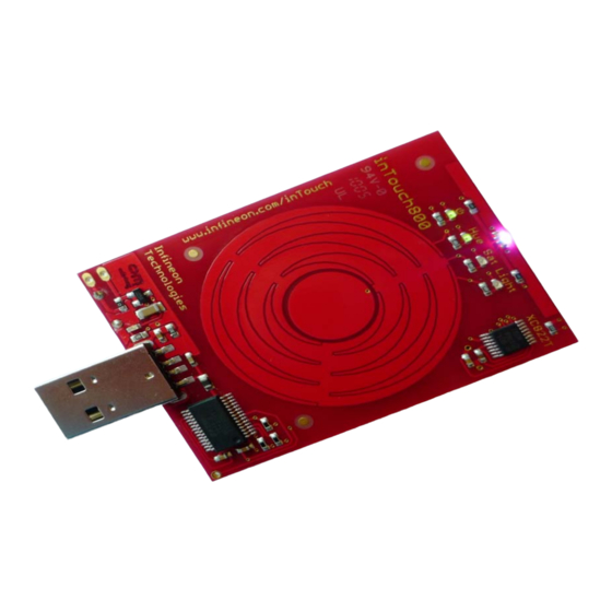
(Figure 1). The kit is built around the XC822T, a member of Infineon Technologies 8-bit microcontrollers XC800 Family, which is capable of capacitive touch detection and LED driving with color control. The implementation comprises of a touch-wheel PCB board consisting of XC822T, the LEDs and the software code running on XC822T. -
Page 6: Color Wheel Features
All manuals and user guides at all-guides.com AP08113 Capacitive-Touch Color Wheel Implementation Color Wheel Features Color Wheel Features The Color Wheel board starts automatically when the kit is plugged into computer (via USB). This is indicated by the ‘On/Off’ LED (see LED4 in Figure 6). -
Page 7: Implementation Of Color Wheel Software
All manuals and user guides at all-guides.com AP08113 Capacitive-Touch Color Wheel Implementation Implementation of Color Wheel Software Implementation of Color Wheel Software The Color Wheel software enables some XC822T device functions, such as Real-Time Clock, Power Down Mode and LEDTSCU for example. When the Color Wheel board is turned off, it actually enters Power Down Mode. The µ... -
Page 8: Touch Detection Methodology For The Touch-Wheel
All manuals and user guides at all-guides.com AP08113 Capacitive-Touch Color Wheel Implementation Implementation of Color Wheel Software The pad detection period depends on many parameters, such as the number of pad turns and LED columns enabled and the accumulation of SFR LTS_TSVAL for example. The ‘All Enabled Pads Accumulated Count Period’... -
Page 9: Touch-Wheel Library
All manuals and user guides at all-guides.com AP08113 Capacitive-Touch Color Wheel Implementation Implementation of Color Wheel Software Touch-Wheel Library The Touch-Wheel Library (Library_TouchWheel.lib) has 2 main functions - calc_touchwheel() and calc_compensation(). The functions are described in this section. 3.2.1 Calc_Touchwheel() Function The calc_touchwheel() function provides the status (i.e. -
Page 10: Rgb Led
All manuals and user guides at all-guides.com AP08113 Capacitive-Touch Color Wheel Implementation Implementation of Color Wheel Software The calc_compensation() function provides the compensation values for Wheel1 and Wheel2 as described in Table 2. The user can call this function during board calibration to obtain an estimation of the compensation values. -
Page 11: Overview Flow Chart Of Color Wheel Software Code
All manuals and user guides at all-guides.com AP08113 Capacitive-Touch Color Wheel Implementation Implementation of Color Wheel Software Overview Flow Chart of Color Wheel Software Code Figure 4 shows the overview flow chart of the Color Wheel software code. Start Initialization of all modules (Handled by XC800_FLOAD.exe, by clicking “Connect”... -
Page 12: Modifying Color Wheel Software Code
Modifying Color Wheel Software Code Modifying Color Wheel Software Code The Color Wheel software example code can be accessed and modified by the user with DAvE-Bench - Infineon’s free tool chain. The user can modify the user-defined parameters (as described in Section 4.1), the timing, code... - Page 13 All manuals and user guides at all-guides.com AP08113 Capacitive-Touch Color Wheel Implementation Modifying Color Wheel Software Code There are two configurations, Debug and Release, available to compile the Color Wheel software code. Select the hex file from the respective folder. To select the required configuration, select: “Project”...
- Page 14 All manuals and user guides at all-guides.com AP08113 Capacitive-Touch Color Wheel Implementation Modifying Color Wheel Software Code Figure 5 DAvE-Bench GUI for Compiling the Color Wheel Software Code Application Note V1.0, 2010-08...
-
Page 15: Downloading Modified Color Wheel Software Code
All manuals and user guides at all-guides.com AP08113 Capacitive-Touch Color Wheel Implementation Downloading Modified Color Wheel Software Code Downloading Modified Color Wheel Software Code The Color Wheel Application Kit is prepared to start up automatically after power-on reset. This is achieved by programming the Boot Mode Index (BMI) to User Mode (Productive). - Page 16 All manuals and user guides at all-guides.com AP08113 Capacitive-Touch Color Wheel Implementation Downloading Modified Color Wheel Software Code MAIN_vInit(); INT.C void INT_vInit(void) NMICON = 0x00; //NMI Control Register IEN0 |= 0x01; // interrupt enable register 0 IEN1 |= 0x00; // interrupt enable register 1 EXICON0 = 0xF3;...
-
Page 17: Implementation Of Color Wheel With Xc822T
All manuals and user guides at all-guides.com AP08113 Capacitive-Touch Color Wheel Implementation Implementation of Color Wheel with XC822T Implementation of Color Wheel with XC822T There are several on-chip modules used in the Color Wheel Application Kit. The configuration and usage of these modules are described in this chapter. -
Page 18: Schematics And Layout Of The Color Wheel Board
All manuals and user guides at all-guides.com AP08113 Capacitive-Touch Color Wheel Implementation Schematics and Layout of the Color Wheel Board Schematics and Layout of the Color Wheel Board Figure 6 shows the component layout of the Color Wheel board, while Figure Figure 8 Figure 9... - Page 19 All manuals and user guides at all-guides.com AP08113 Capacitive-Touch Color Wheel Implementation Schematics and Layout of the Color Wheel Board Figure 8 Schematic of USB Interface on the Color Wheel Board Figure 9 Schematic of power supply of the Color Wheel Board Application Note V1.0, 2010-08...
- Page 20 All manuals and user guides at all-guides.com AP08113 Capacitive-Touch Color Wheel Implementation Schematics and Layout of the Color Wheel Board Figure 10 Figure 11 show the top and bottom layout of the Color Wheel board respectively. Figure 10 Top Layout of the Color Wheel Board Figure 11 Bottom Layout of the Color Wheel Board Application Note...
-
Page 21: Summary
The capacitive touch-sensing capability of the Infineon XC82x and XC83x Microcontrollers opens the door to a wide variety of applications. The Infineon touch-sensing solution described in this document is a total solution on- chip, comprising optimized hardware and effective software functions running from ROM. By taking the example provided and working with the Infineon’s free tool-chain, the development of new applications for these devices is... - Page 22 All manuals and user guides at all-guides.com w w w . i n f i n e o n . c o m Published by Infineon Technologies AG...
Need help?
Do you have a question about the XC800 AP08113 and is the answer not in the manual?
Questions and answers