Advertisement
Advertisement
Table of Contents

Subscribe to Our Youtube Channel
Related Manuals for Sunny Health & Fitness SF-S0637


Summary of Contents for Sunny Health & Fitness SF-S0637
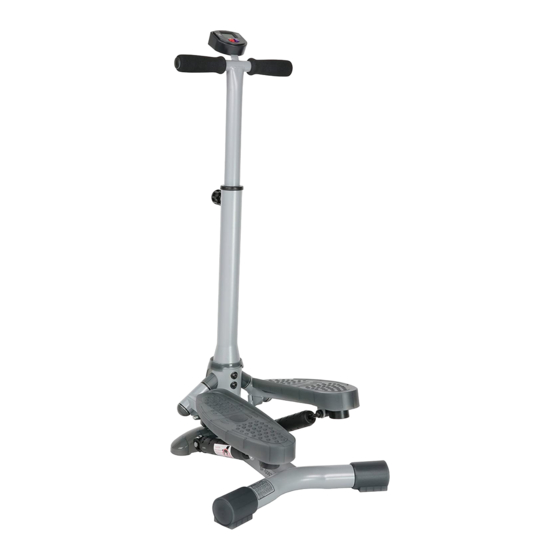
- Page 1 TWIST-IN STEPPER WITH HANDLEBAR SF-S0637 USER MANUAL IMPORTANT! Please retain owner’s manual for maintenance and adjustment instructions. Your satisfaction is very important to us, PLEASE DO NOT RETURN UNTIL YOU HAVE CONTACTED US: support@sunnyhealthfitness.com or 1- 877 - 90SUNNY (877-907-8669).
- Page 2 IMPORTANT SAFETY INFORMATION We thank you for choosing our product. To ensure your safety and health, please use this equipment correctly. It is important to read this entire manual before assembling and using the equipment. Safe and effective use can only be achieved if the equipment is assembled, maintained and used properly.
- Page 3 NOTE: We recommend that you place a non-slip mat underneath the stepper to protect your carpet or floor. Always make sure that the product is placed on a flat and non-skid surface. Check all connections and moving parts on a regular basis. Damaged parts have to be changed immediately.
- Page 4 EXPLODED DIAGRAM HARDWARE PACKAGE #37 M8 x 24.5 4 PCS 1 PCS # 27 1 PCS #36 4 PCS #13 2 PCS...
- Page 5 PARTS LIST DESCRIPTION SPECIFICATION Main Frame Pedal Holder, Right Pedal Holder, Left Hydraulic Cylinder Pedal, Right Pedal, Left Front Base Support Plastic Spacer Meter Magnet Axle 16x170 mm Square Plastic Bushing 25.4 mm Plastic End Piece Plastic Bushing 38 mm Plastic Spacer C-Ring Plastic Cap...
- Page 6 ASSEMBLY INSTRUCTIONS STEP 1: Put the 2 Plastic End Pieces (No. 13) onto the rear tubes on the Main Frame (No. 1). Make sure the ball pins pop into the holes on the bottom of the rear tubes. STEP 2: (1) Insert the meter wire into the hole at the top of the Handlebar (No.
- Page 7 STEP 3: (1) Pull the Cover (No. 27) up. #37 M8 x 24.5 4 PCS 1 PCS #36 4 PCS # 27 1 PCS (2) Connect the meter wire to the Wire A (No. 29) in the Main Frame (No. 1). (3) Lower the Handlebar Tube (No.
- Page 8 BATTERY: Prior to first use of the product you have to install the battery. If the display is not working properly, change the battery. To change the battery, remove the meter from the handlebar. The battery compartment is located at the back of the meter. After you change the battery, put the meter back on the handlebar.
Need help?
Do you have a question about the SF-S0637 and is the answer not in the manual?
Questions and answers