Advertisement
Advertisement
Table of Contents

Related Manuals for Sunny Health & Fitness SF-S0636


Summary of Contents for Sunny Health & Fitness SF-S0636
- Page 1 TWIST-IN STEPPER SF-S0636 USER MANUAL IMPORTANT! Please retain owner’s manual for maintenance and adjustment instructions. Your satisfaction is very important to us, PLEASE DO NOT RETURN UNTIL YOU HAVE CONTACTED US: support@sunnyhealthfitness.com or 1- 877 - 90SUNNY (877-907-8669).
-
Page 2: Important Safety Information
IMPORTANT SAFETY INFORMATION We thank you for choosing our product. To ensure your safety and health, please use this equipment correctly. It is important to read this entire manual before assembling and using the equipment. Safe and effective use can only be achieved if the equipment is assembled, maintained and used properly. - Page 3 A) This product has been tested in accordance with the requirements of EN 957-1, 957-8 standard, class H (home use). The maximum load is limited to 100 kg. B) The CE marking of this item is in regard to the electromagnetic compatibility (EC- directive 89/EWG) as well as to the electrical safety.
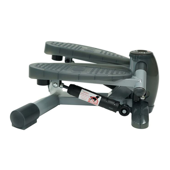
- Page 4 EXPLODED DIAGRAM...
-
Page 5: Parts List
PARTS LIST DESCRIPTION SPECIFICATION Main Frame Pedal Holder, Right Pedal Holder, Left Hydraulic Cylinder Pedal, Right Pedal, Left Front Base Support Plastic Spacer Meter Magnet Axle 16x170 mm Square Plastic Bushing 25.4 mm Plastic End Piece 38 mm Plastic Bushing Plastic Spacer C-Ring Plastic Cap... -
Page 6: Assembly Instructions
ASSEMBLY INSTRUCTIONS Put the 2 Plastic End Pieces (No. 13) onto the rear tube on the Main Frame (No. 1). Make sure the ball pins pop into the holes on the bottom of the rear support. See drawing below. - Page 7 BATTERY INSTALLATION AND REPLACEMENT If the meter display is not clear, try replacing the battery. The stepper uses 1 x 1.5V AAA battery. To replace the battery, use the notch that is next to the button and gently pull the meter up slightly to loosen.
Need help?
Do you have a question about the SF-S0636 and is the answer not in the manual?
Questions and answers