Table of Contents
Advertisement
Available languages
Available languages
Quick Links
IMPORTANT
Read and save these instructions. This guide should be kept by the installer.
HM750A1000
ADVANCED ELECTRODE STEAM HUMIDIFIER
INTRODUCTION
The HM750 is the most advanced residential steam
humidifier available and provides steady and reliable
humidification for a home. The humidifier is designed for
connection directly to a supply air duct for humidity on
demand. The humidifier may be directly mounted to the air
duct, or remotely from the air duct, with a steam hose
connecting the humidifier to a distributor nozzle installed
at the air duct.
Included in the Box
—
HM750 steam humidifier
—
H6062 HumidiPRO
—
Steam distributor nozzle
—
Rubber drain hose
—
LDPE water hose
—
Baffle (duct mount only)
—
Foam gasket (duct mount only)
—
Steam hose (wall mount only)
—
Fittings, hardware, and mounting template
—
Installation Instructions, 33-00289EF (this document)
—
Annual Operation and Maintenance Reminder
INSTALLATION INSTRUCTIONS
Tools Needed
—
Flat-head screwdriver
—
Phillips screwdriver
—
Wrench
—
Copper pipe (optional)
—
Level
—
Hole saw
Humidifier Configuration
The HM750 is configured at the factory to operate under
most conditions without the need to change its
configuration.
NOTE: Because the humidifier is factory configured for
optimal performance, Resideo strongly
discourages changes to the configuration of the
humidifier not described in these instructions.
Before Installation
1. Ensure that available voltage and phase
corresponds with humidifier voltage and phase as
indicated on humidifier's specification label.
2. Ensure that the dedicated external fuse disconnect
is of sufficient size to handle the rated amps as
indicated on the specification label. Refer to local
codes.
3. Ensure sufficient clearances will be available as
described in the Location section on page 6.
4. If the humidifier will be wall mounted, ensure steam
lines can be routed to duct as described in the Steam
Line Instructions on page 7.
33-00289EF-03
Advertisement
Table of Contents

Subscribe to Our Youtube Channel
Related Manuals for Honeywell Home HM750


Summary of Contents for Honeywell Home HM750
- Page 1 — Level — Hole saw Humidifier Configuration The HM750 is configured at the factory to operate under most conditions without the need to change its configuration. NOTE: Because the humidifier is factory configured for optimal performance, Resideo strongly discourages changes to the configuration of the humidifier not described in these instructions.
- Page 2 Water quality • Resideo does not accept any liability for The HM750 requires a cold water connection from installations of humidity equipment installed by your home's main water supply between 15- unqualified personnel or the use of 100 PSIG.
-
Page 3: Parts And Accessories
HM750A1000 Parts and Accessories The following parts and accessories are available and may have been included with your HM750 humidifier. The cylinder is the only item that will need periodic replacement to maintain proper humidifier operation. Table 2. Parts and accessories. - Page 4 120 V and 22 GPD when run on 240 V. See Figure 20 sized properly. Do not use square feet when sizing for details on configuring the HM750 to run on a different a humidifier installation. Instead, cubic feet must voltage.
- Page 5 240 VAC 240VAC MAIN SUPPLY OFF ON ALWAYS INSTALL L2/N A WATER USE 1/2 IN. OD COPPER SHUT-OFF VALVE. TO WITHIN 4 FT (1.2 M) GROUND OF HUMIDIFIER. (OPTIONAL) ELECTRICAL M37185 Fig. 2. Typical HM750 Installation. Measurements in inches (mm). 33-00289EF—03...
-
Page 6: Steam Nozzle Location
• When possible, mount the HM750 humidifier at a height convenient for servicing. NOTE: Do not mount on surfaces above 176 °F (80 °C), 1/2 DUCT where freezing can occur, vibrating surface, or floor. -
Page 7: Steam Line Instructions
Steam Line Instructions The following instructions must be followed for installation of steam lines for the HM750. Failure to use recommended material (see Table 5), or failure to follow any other steam line installation instructions will result in improper operation and could void the warranty. -
Page 8: Steam Line Installation Examples
MINIMUM 12 (305) MINIMUM 12 (305) RADIUS MINIMUM RADIUS SUPPORT BRACKETS SUPPORT BRACKETS CONNECT STEAM HOSE TO CYLINDER OBSTRUCTION HM750 Status Idle Filling Humidifying Draining Service Cylinder Fault Power Drain Fault Codes In Front Cover (305) HM750 Status Idle MINIMUM... -
Page 9: Mounting The Humidifier
HM750A1000 MOUNTING THE HUMIDIFIER The HM750 can be mounted either directly on a supply air 3. Drill a 1-3/4” hole in the duct for the steam duct or remotely mounted on a wall. When remotely distributor nozzle. Attach the steam hose to the... -
Page 10: Mounting To The Supply Duct
HM750A1000 Mounting to the Supply Duct The HM750 can also be mounted directly onto the supply INSTALL THE STEAM NOZZLE duct. In this case, the steam guide must be removed and 1. Install the nozzle with baffle directly onto the... -
Page 11: Connecting The Water Supply Line
— Drain water is automatically cooled to 160 °F NOTE: To remove the water supply line, the floating tip of (71 °C) when HM750 cycles a drain. When an the fill connection is pushed in slightly, which will emergency drain occurs, temperature may be release the grip on the water supply line. -
Page 12: Voltage Selection
HM750A1000 ELECTRICAL WARNING To comply with UL product listing, the HM750 must be hardwired to a dedicated 15 amp circuit. CAUTION All wiring must be done per governing electrical Wiring to be performed by a licensed electrician. codes. Failure to do so will void the product Installation on a GFCI circuit is recommended. -
Page 13: Low-Voltage Controls
When distributing steam into a duct, there could be a call solid wire and keep as short as possible. for humidity when there is no air flow. The HM750 with Humidity Control HumidiPRO control or some other thermostat can be •... - Page 14 NOTE: If a Prestige, VisionPRO, Round Smart (or similar) is used to control humidity, wire the two U contacts from thermostat to HUM and HUM on the HM750. With the jumper in place between AP terminals on the HM750, only these two wires are necessary to control humidity.
-
Page 15: Installation Check
LEDs and sequences. period of time for the HM750 to reach full output capacity. It may take several hours with low • If an error is detected during the self-diagnostic conductivity water. -
Page 16: Operation
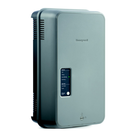
LED will flash on and off, during which time the humidifier will continue to operate as normal. After 7 The HM750 user interface includes a series of LEDs that days of flashing, the LED will remain on solid, and the provide information about the humidifier status. - Page 17 HM750A1000 STEAM OUTLET FILL HIGH WATER SENSOR CYLINDER PLUGS STEAM CYLINDER HM750 Status USER Idle Filling INTERFACE Humidifying Draining Service Cylinder POWER/DRAIN Fault BUTTON Power Drain Fault Codes In Front Cover FILL VALVE DRAIN VALVE QUICK DRAIN CONNECTOR OUTLET M37211 Fig.
-
Page 18: Maintenance And Servicing
Accumulation of debris on the strainer can NOTE: As long as the HM750 is powered, it will lead to reduced inlet water flow or complete blockage. automatically drain the cylinder when there has... -
Page 19: Replacement Parts
HM750A1000 REPLACEMENT PARTS CYLINDER REPLACEMENT KIT CAUTION Before Servicing Product Number: HM750ACYL 1. Disconnect main power source before accessing internal compartments. Dimensions: See Fig. 27 2. The plumbing and electrical compartments contain high voltage components and wiring. Included in the Box Access should be limited to licensed HVAC •... -
Page 20: Removing The Cylinder
HM750A1000 Removing the Cylinder 5. Remove the high level water sensor connections. 6. Remove the cylinder plugs from the cylinder pins by pulling vertically. 7. Using a flat screwdriver or 5/16 in. nut driver, loosen WARNING the hose clamp closest to the cylinder. Disconnect main power source before accessing 8. - Page 21 HM750A1000 Drain Valve Removal (for cleaning or replacement) Always clean the drain valve before installing a new cylinder. Scale from the spent cylinder may have fallen into the drain valve and could prevent its proper operation. To properly clean the drain valve it must be removed and disassembled. WARNING 2.
-
Page 22: Control Board Replacement
HM750A1000 Inlet Valve Strainer Cleaning Opening Electrical Compartment Depending on the water quality, periodic cleaning of the fill valve strainer may be required. This can be performed WARNING without removing the valve from humidifier. Disconnect main power source before accessing internal compartments. -
Page 23: Inlet Valve Replacement
HM750A1000 Inlet Valve Replacement 3. SLIDE FORWARD WARNING 1. DISCONNECT Disconnect main power source before accessing SOLENOID internal compartments. WIRING The inside of the humidifier cabinet contains high 4. LIFT UP INLET VALVE voltage components and wiring. Access should be limited to authorized personnel. -
Page 24: Troubleshooting Requirements
• The wiring diagram for your specific humidifier is installed on the inside of the humidifier door. A generic CAUTION copy of the HM750 wiring diagram is also included at Burn and Scalding Hazard. the end of this chapter for reference purposes. -
Page 25: Clearing A Fault
When an abnormal condition occurs that cannot be self- • Press and hold the Power/Drain button for 5 seconds. corrected by the software, the HM750 will turn off power The humidifier will begin to drain and, when drained, to the cylinder, drain the cylinder, and annunciate the fault will power off. - Page 26 HM750A1000 Service LED Symptom Cause Corrective Action(s) Fault 3 Insufficient Cylinder plugs installed incorrectly Check that cylinder plugs are completely seated flashes Current on cylinder. Fill valve activated Fill valve inlet filter clogged Check fill valve inlet filter and clean if required. for long time, but high water level not reached.
- Page 27 HM750A1000 ORANGE BLACK BLACK ELECTRODES TO CARTRIDGE MAIN SUPPLY L1 L2/N GND STEAM CARTRIDGE AIR PROVING AIR PROVING SW FUSE T2A 250V HUMIDISTAT 24VAC HUMIDISTAT VOLTAGE SELECTION EXTERNAL 120VAC 240VAC IDLE LED FILLING LED HUMIDIFYING LED DRAINING LED TRANSFORMER BLACK BLUE CYLINDER FILL VALVE...
-
Page 28: Year Limited Warranty
Resideo Inc., 1985 Douglas Drive North, Golden Valley, MN 55422 www.resideo.com 33-00289EF—03 M.S. Rev. 02-19 | Printed in United States ©2019 Resideo Technologies, Inc. All rights reserved. The Honeywell Home trademark is used under license from Honeywell International Inc. -
Page 29: Instructions D'installation
Niveau à bulle — Scie à trous Configuration de l’humidificateur Le HM750 est configuré en usine pour fonctionner dans la plupart des conditions sans qu’il soit nécessaire de modifier sa configuration. REMARQUE : L’humidificateur étant configuré en usine pour offrir des performances optimales, Resideo déconseille vivement d’apporter... - Page 30 à haute tension. L’accès doit être limité N’installez pas l’appareil sur le sol. au seul personnel autorisé. Le HM750 génère de la vapeur à la pression • Pendant le fonctionnement de l’humidificateur atmosphérique. Ne reliez aucun appareil et après, la vapeur et les composants en contact susceptible de bloquer l’évacuation de la vapeur à...
-
Page 31: Pièces Et Accessoires
HM750A1000 Pièces et accessoires Les pièces et accessoires suivants sont disponibles et peuvent être inclus avec votre humidificateur HM750. Le cylindre est le seul élément qui doit être remplacé régulièrement pour maintenir le bon fonctionnement de l’humidificateur. Tableau 2. Pièces et accessoires. - Page 32 HM750A1000 DIMENSIONNEMENT IMPORTANT Le HM750 produit 41,6 litres (11 gallons) par jour (l/j) Valider les dimensions du volume à couvrir avant lorsqu’il est branché sur 120 V et 83,3 l/j (22 gallons) d'installer le HM750. N’utilisez pas la mesure de la lorsqu’il est branché...
- Page 33 CUIVRE DE DIAM. EXT. INSTALLEZ LIGNE L2/N DE 12,7 MM DANS UN TOUJOURS RAYON DE 1,2 M (4 PI) UN ROBINET TERRE DE L’HUMIDIFICATEUR. D’ARRÊT D’EAU. (FACULTATIF) ÉLECTRICITÉ MF37185 Fig. 2. Installation type du HM750. Mesures en po (mm). 33-00289EF—03...
- Page 34 (montage à distance) 36 PO (914 MM) POUR PERMETTRE L’ACCÈS AU CÂBLAGE. MF36860A Fig. 3. Dégagements requis pour le HM750 Emplacement de la buse de Consultez les codes locaux et nationaux avant de choisir distribution de vapeur l’emplacement final et de procéder à...
- Page 35 HM750A1000 LARGEUR D’1/2 CONDUIT ÉCOULEMENT D’AIR MF37233 Fig. 6. Buse de distribution installée horizontalement sur un conduit vertical (montage à distance) 33-00289EF—03...
- Page 36 Instructions pour les lignes de vapeur Veuillez suivre les instructions ci-dessous pour l’installation des lignes de vapeur du HM750. La non-utilisation du matériel recommandé (voir le Table 5) ou le non-respect de toute autre instruction d’installation des lignes de vapeur se traduira par un fonctionnement incorrect et pourrait annuler la garantie.
- Page 37 MINIMUM MINIMUM DE 12 (305) DE 305 (12) SUPPORTS DE MONTAGE SUPPORTS DE MONTAGE CONNEXION DU TUYAU DE VAPEUR AU OBSTRUCTION CYLINDRE HM750 Status Idle Filling Humidifying Draining Service Cylinder Fault Power Drain Fault Codes In Front Cover (305) HM750...
-
Page 38: Montage Mural
à distance, la buse de distribution est montée plus que 6 mm (0,25 po) exposés. Suspendez l’humidi- sur un conduit et reliée au HM750 par un tuyau de vapeur. ficateur à la tête de la vis par le trou de serrure (Fig. 12). - Page 39 HM750A1000 Montage sur le conduit d’alimentation Le HM750 peut également être monté directement sur le INSTALLEZ LA BUSE DE DISTRIBUTION DE VAPEUR conduit d’alimentation. Dans ce cas, vous devez retirer le 1. Installez la buse avec le déflecteur directement sur guide de vapeur et le remplacer par la buse de vapeur et le l’humidificateur à...
- Page 40 LDPE, fournie avec l’équipement) sur le raccord — L’eau de vidange est automatiquement refroidie à d’alimentation (Fig. 18). Pour ce faire, insérez la conduite 71 °C (160 °F) lorsque le HM750 effectue un cycle de d’eau dans le raccord rapide. vidange. Lorsqu’une vidange d’urgence est effectuée, il est possible que la température soit plus élevée.
-
Page 41: Sélection De La Tension
SUPPLY (alimentation principale) (L1, L2/N, et entre les bornes appropriées du panneau de commande GND) situées sur le panneau de commande de de l’humidificateur. Le HM750 est configuré en usine pour l’humidificateur. fonctionner sur un circuit de 240 V c.a. Si l’humidificateur doit être branché... - Page 42 • Vous pouvez l’installer sur le conduit de retour (de d’air. Il est possible d’utiliser le HM750 avec le contrôleur préférence) ou dans la pièce humidifiée. HumidiPRO ou un autre thermostat pour activer un •...
- Page 43 REMARQUE : Si un appareil Prestige, VisionPRO, Round Smart (ou un appareil semblable) est utilisé pour contrôler l’humidité, câblez les deux contacts en U du thermostat à HUM et HUM sur le HM750. Avec le cavalier en place entre les bornes AP du HM750, seuls ces deux fils sont requis pour le contrôle de l’humidité. Assurez- vous de configurer le thermostat de manière à...
-
Page 44: Vérification De L'installation
Marche/arrêt courant d'air par le détecteur de présence d'air. Une Le HM750 est configuré en usine pour fonctionner en tant fois la détection confirmée, le voyant DEL vert qu’humidificateur avec commande de marche/arrêt. Il se clignotant devient fixe et l’humidificateur... - Page 45 Vous devez remplacer le cylindre. Reportez-vous à la section « Kit L’interface utilisateur du HM750 comprend une série de de remplacement du cylindre » à la page 20. voyants DEL qui fournissent des informations sur l’état de l’humidificateur.
- Page 46 HM750A1000 SORTIE DE VAPEUR GODET DE REMPLISSAGE CAPTEUR DE NIVEAU D’EAU ÉLEVÉ CONNECTEURS HAUTE TENSION DU CYLINDRE CYLINDRE DE VAPEUR HM750 Status INTERFACE Idle Filling UTILISATEUR Humidifying Draining Service Cylinder BOUTON Fault ALIMENTATION/VIDANGE Power Drain Fault Codes In Front Cover...
-
Page 47: Entretien Et Révision
REMARQUE : Tant que le HM750 est alimenté, il vidange système. L’accumulation de débris sur le filtre peut réduire automatiquement le cylindre lorsqu’il n’y a le débit d’eau en entrée ou le bloquer complètement. -
Page 48: Pièces De Rechange
HM750A1000 PIÈCES DE RECHANGE KIT DE REMPLACEMENT DU MISE EN GARDE CYLINDRE Avant l’entretien 1. Débranchez la source d’alimentation principale Numéro de produit :HM750ACYL avant d’accéder aux compartiments internes. 2. Les compartiments électriques et de la Dimensions :Voir la Fig. 27 plomberie contiennent des composants et des câblages à... - Page 49 HM750A1000 Retrait du cylindre 5. Retirez le connecteur du détecteur de niveau d’eau élevé. 6. Retirez les connecteurs haute tension du cylindre des broches du cylindre en les tirant à la verticale. AVERTISSEMENT 7. À l’aide d’un tournevis plat ou d’une clé à douille de Débranchez la source d’alimentation principale 5/16 po (7,9 mm), desserrez le collier de serrage le avant d’accéder aux compartiments internes.
- Page 50 HM750A1000 Retrait de la soupape de vidange (brosse à dents) ou d’un chiffon humide. N’utilisez PAS de brosse métallique ou d’agents de nettoyage (pour nettoyage ou remplacement) chimiques car la pièce risquerait d’être Nettoyez toujours la soupape de vidange avant d’installer endommagée.
- Page 51 HM750A1000 Nettoyage du filtre de la soupape Ouverture du compartiment électrique d’arrivée En fonction de la qualité de l’eau, un nettoyage régulier du AVERTISSEMENT filtre de la soupape de remplissage peut se révéler nécessaire. Cette opération peut être réalisée sans retirer Débranchez la source d’alimentation principale la soupape de l’humidificateur.
- Page 52 HM750A1000 4. Après avoir vérifié que la rondelle en plastique est 10. Suivez les étapes ci-dessus dans l’ordre inverse pour insérée entre la tête de la vis et le panneau de installer la nouvelle soupape d’arrivée. commande, resserrez la vis de retenue du panneau 11.
-
Page 53: Dépannage
Eau de faible conductivité S’il a été utilisé avec de l’eau de faible conductivité, il peut falloir de consigne plusieurs heures au HM750 pour atteindre sa pleine capacité. C’est d’humidification normal. Pendant ce temps, l’humidificateur n’effectue aucune (% HR). - Page 54 Erreurs du HM750 répertorie les séquences d’erreur qui peuvent s’afficher, leur signification, la ou les causes possibles et les mesures Le système d’autodiagnostic intégré au HM750 surveille correctives suggérées. en continu le fonctionnement de l’humidificateur. Lorsqu’une condition anormale survient et qu’elle ne peut Annulation d’une erreur...
- Page 55 HM750A1000 Voyant DEL Service Symptôme Cause Mesure(s) corrective(s) Fault (Défaut) Courant Conncteurs du cylindre installés Vérifiez que les connecteurs haute tension sont insuffisant incorrectement insérés à fond sur le cylindre. clignotements Soupape de Filtre d’arrivée de la soupape de Vérifiez le filtre d’arrivée de la soupape de remplissage remplissage obstrué...
- Page 56 HM750A1000 ORANGE NOIR NOIR ÉLECTRODES VERS ALIMENTATION PRINCIPALE LA CARTOUCHE L1 L2/N GND CARTOUCHE DE VAPEUR AIR PROVING DISPOSITIF DE VÉRIFICATION DE PRÉSENCE D'AIR FUSIBLE T2A 250 V HUMIDISTAT 24 Vca HUMIDISTAT SÉLECTION DE LA TENSION EXTERNAL 120 Vca 240 Vca DEL VEILLE DEL REMPLISSAGE DEL HUMIDIFICATION...
-
Page 57: Garantie Limitée De 5 Ans
HM750A1000 GARANTIE LIMITÉE DE 5 ANS Resideo garantit ce produit, à l’exception des piles, contre tout défaut de pièce ou de main-d’œuvre, durant une période pour cinq (5) ans à partir de la date d’achat par le consommateur d’origine si le produit est utilisé et entretenu convenablement. - Page 58 HM750A1000 33-00289EF—03...
- Page 59 HM750A1000 33-00289EF—03...
- Page 60 HM750A1000 Resideo Inc., 1985 Douglas Drive North, Golden Valley, MN 55422 www.resideo.com 33-00289EF—03 M.S. Rev. 02-19 | Imprimé aux États-Unis Tous droits réservés. La marque de commerce Honeywell Home est utilisée sous licence avec l’autorisation d’Honeywell International Inc.
Need help?
Do you have a question about the HM750 and is the answer not in the manual?
Questions and answers