Table of Contents
Advertisement
Quick Links
Advertisement
Table of Contents

Related Manuals for TREND T5MK1 V2


Summary of Contents for TREND T5MK1 V2
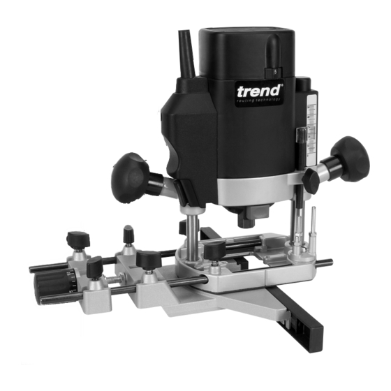
- Page 1 MK 1 & MK 2 V2 Released May 2009...
-
Page 2: Table Of Contents
Dear Customer TECHNICAL DATA Thank you for purchasing this Trend product, we hope you enjoy many years of creative and Voltage: UK & Eire 240V productive use. UK & Eire only 115V Please remember to return your guarantee card Europe 230V within 28 days of purchase. -
Page 3: Safety
SAFETY and balance at all times. Do not use recommended when working awkward or uncomfortable hand outdoors. Wear protective hair WARNING: positions. covering to contain long hair. Observe the safety regulations in the 17. Don’t abuse the cable. Never carry 5. - Page 4 15. All fastening screws and nuts should be adhered to. Recommended speeds ensure there is sufficient clearance be tightened using the appropriate are shown in the Trend Routing between cutter tip and inside edge of spanner or key and to the torque Catalogue and/or website.
-
Page 5: Electrical Safety
1.00 below. If you are in doubt, contact an authorised 1.50 Trend repair agent or a qualified electrician. 2.50 s Disconnect the plug from the supply. 4.00 s Cut off the plug and dispose of it safely; a... -
Page 6: Manufacturers Declaration
INFORMATION ON NOISE/VIBRATION The noise level when working can exceed 85 dB(A). Wear ear protection! Weighted root mean square acceleration value according to EN 60745: < 2.5 m/s (hand arm method) Managing Director Jeff Willcocks Trend Machinery & Cutting Tools Ltd. -
Page 7: Description Of Parts
DESCRIPTION OF PARTS A Plunge locking grip knob B Depth of cut scale C Depth stop D Motor housing E Power cable F On/Off switch: MK1 G Fixed Grip knob H Spindle lock Collet nut Dust spout 35mm dia. K Thumb knob with anti-vibration spring to secure fence rods L Router base M Template guide bush dia. -
Page 8: Assembly & Adjustment
ASSEMBLY & ADJUSTMENT Fitting and Removing the Dust Extractor Spout s Insert the extractor spout in channel ‘A’ of the 35mm routing base. The extractor spout is suitable for dust extractors with a hose diameter of 35mm. The spout can be installed from either side. To Fitting Dust ensure maximum plunge it is recommended Extractor... -
Page 9: Switching On & Off
Switching On & Off T5 MK1 The T5MK2/LOCK must not be used s A slide switch above the fixed grip knob is without a No-Volt Release Switch. used to turn the router on and off. s The T5 has a soft start feature when switched Adjusting the Depth of Cut on and will take 1–2 seconds to reach full running speed. -
Page 10: Fitting & Removing Cutters
How to Fit and Remove a Router Cutter Fitting Cutters s Insert at least of the shank length of the cutter (1) into the collet. s Press the spindle lock (2) forward until the router spindle is locked (you may need to turn the spindle slightly to engage it). -
Page 11: Speed Control
Fixing Points for Accessories 15mm The router has two threaded holes M6 in its base that allow fitting of accessories and also fitting to router tables. A whole range of accessories are shown in the Trend Routing Catalogue. -10-... -
Page 12: Operation
OPERATION Cutting Direction Sequence of plunging The direction of routing must always be opposite to the cutter’s direction of rotation. Otherwise there is a risk of Step One kick-back. Plunge down and lock the motor carriage, with the plunge locking grip knob. Feed direction of router Step Two... -
Page 13: Side-Fence Routing
Side-Fence Routing The side-fence is used to guide the router when moulding, edge profiling or rebating the edge of the workpiece or when routing grooves and slots in the centre of the workpiece, parallel to the edge. The edge of the workpiece must be straight and true. -
Page 14: Template Guide Bush Routing
Using the Guide Bush The 20mm guide bush (1) is fastened to the router’s base from beneath using the two M5 countersunk machine screws (2) supplied. Routing with a Template The guide bush is used in conjunction with a template when the routing operation is repetitive or the workpiece is complex in shape. -
Page 15: Beam Trammel Routing
Beam Trammel Routing Cutting Arcs with the Router s Place the machine on the workpiece. s Set the cutting depth using the depth stop (2). s Fasten the fence rod (1) in the routing base (3) with the thumb knob (4). s Fit on the beam trammel point (5) as shown. -
Page 16: Bearing Guided Cutters
Bearing Guided Cutters Ball Bearing Guided Cutters Edge profiling and shaping cutters are available with a bearing fitted to the end. This enables shaped or straight workpieces to be routed without the need for a guiding device such as a side-fence or batten. -
Page 17: Freehand Routing & Batten Routing
Freehand Routing with the Router The T5 can also be used for signwriting or creative freehand work without any form of guide. With practice, numbers or name plate designs can be routed freehand. Draw the design or motif on the workpiece and then rout the design, taking shallow passes. -
Page 18: Maintenance & Care
Please call Trend Customer Services for advice as to how to dispose of unwanted Trend electrical product in an environmentally safe way It is advisable to have the or visit www.trend-uk.com... -
Page 19: Spare Parts List
& - SPARE PARTS LIST v9.0 01/2009 Qty. Desc. Ref. Stator Housing WP-T5/001 Top Vent Housing WP-T5E/002 Base Complete V2 WP-T5/003A Lower Bearing Housing V2 WP-T5/004A Spring for Revolving Guide WP-T5/005 Ball for Revolving Guide WP-T5/006 Revolving Guide V2 WP-T5/008A Nut Hex M5 WP-NUT/05 Threaded Pin M5 x 30mm Revolving Guide... - Page 20 & - SPARE PARTS LIST v9.0 01/2009 Qty. Desc. Ref. Parallel Side Fence Complete with Micro Adjuster WP-T5/046 Parallel Side Fence Casting >05/2005 WP-T5/047A Micro Adjuster Knurled Knob >05/2005 WP-T5/048A Side Fence Cheeks (set) >05/2005 WP-T5/049A Phenolic Base Plate Slider WP-T5/050 Machine Screw Cheese M5 x 10mm Slot WP-SCW/50...
-
Page 21: Spare Parts Diagram
T5 MK1 V2 - SPARE PARTS DIAGRAM v9.0 01/2009 T5 MK2 V2 - SWITCH -20-... - Page 22 Web: __________________www.trend-uk.com RECYCLABLE © Copyright Trend 2009. No part of this publication may be reproduced, stored or transmitted in any form without prior permission. Our policy of continuous improvement means that specifications may change without notice. Trend Machinery and Cutting Tools...
Need help?
Do you have a question about the T5MK1 V2 and is the answer not in the manual?
Questions and answers