Table of Contents
Advertisement
Quick Links
Advertisement
Table of Contents

Related Manuals for TREND PRT


Summary of Contents for TREND PRT
- Page 2 SAFETY Keep work area clean. Cluttered oil and sharp edges. Always trail workshops and benches can the power cord away from the cause injuries work area. Observe the safety regulations in the instruction manual of the Power Use the attachment with the Connect dust extraction Tool to be used or connected to this power tools and accessories...
- Page 3 Recommended speeds can be found on the packaging, in cutter After work, release the router instructions or in the Trend plunge to protect the cutter. Routing Catalogue. Always use a push-stick or push- Always use router cutters in a block for last 300mm of the cut.
-
Page 4: Electrical Safety
Should your mains plug need replacing and you are competent to do this, proceed as instructed below. If you are in doubt, contact an authorised Trend repair agent or a qualified electrician. Using an Extension Cable Disconnect the plug from the supply. -
Page 5: Items Enclosed
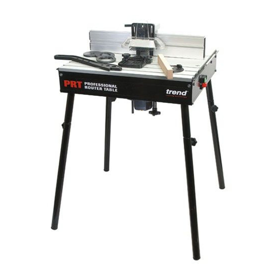
ITEMS ENCLOSED... - Page 6 DESCRIPTION OF PARTS Table top Insert rings Back fence Scale Dust port Side pressure guard Top pressure guard Fence cheek Guard Pivot guard lock Floor legs Bench legs Lead on pin Router trigger lock strap Mitre fence Lead on pin park Pushstick Mitre fence slot Back fence slots/keyhole...
- Page 7 ASSEMBLY Fitting Legs...
- Page 8 Router Compatibility See machine screw illustrations on opposite page. Three machine screws (B) are supplied as standard with the PRT table Screw Make Router Model x Qty TREND T3, T5, T5 Mk2 B X 2 TREND B X 3 B&Q PERFORMANCE...
- Page 9 Re-drilling Middle Extrusion Only Screw Selection Remove middle extrusion from table by turning cam locks. Remove the plastic base of the router. Alternatively a photocopy or an outline of the base can be made of the plastic base instead. M5x16mm M6x16mm Align the centre of the middle extrusion to the router base and secure them together.
-
Page 10: Fitting Insert Rings
Fitting Insert Rings 16mm 20mm 30mm 35mm 50mm 54mm SCALE 64mm 68mm 86mm 90mm -10-... - Page 11 Fitting Back Fence -11-...
- Page 12 Fitting Top Guard & Top Pressure SCALE 10mm max. SCALE SCALE max. SCALE -12-...
- Page 13 Fitting Side Pressure Position 1 Position 2 70mm Position 3 -13-...
- Page 14 Fitting Mitre Fence -14-...
- Page 15 Dust Extraction - Fitting Hose -15-...
-
Page 16: Operation
OPERATION No-Volt Release Switch Plug machine into trailing socket. Put plug of switch into mains supply. Switch on router Press green button to switch on. To switch off press red button. Isolate from power supply when making any adjustments. -16-... - Page 17 Back Fence Adjustment Adjust back fence position by loosening two knobs (A) and pushing fence forwards or backwards. Lock fence position by tightening the two knobs (A). To adjust fence cheeks loosen four back knobs (B). Slide cheeks in and out to suit cutter.
- Page 18 Edge Moulding and Grooving Isolate from power source. Fit cutter. Set back fence position. Set top and side pressures. Fit guard. Check all knobs are tight. Plug into power supply. Switch on. Feed right to left. Switch off. -18-...
- Page 19 Stopped Moulding Isolate from power supply. Fit cutter. Set back fence position. Fit some stops to back fence using cramps. Fit guard. Check all knobs are tight Plug into power supply. Switch on. Drop material against infeed stop A and pivot into cutter.
-
Page 20: Mitre Fence
Mitre Fence Isolate from power supply. Fit cutter. Adjust angle of mitre fence by loosening knob and turning protractor head to line up angle required with arrow. Place component onto mitre fence. Plug into power supply. Feed right to left holding component securely. - Page 21 Lead-on Pin Isolate from power supply. Fit lead-on pin into threaded hole using a slotted screwdriver. Move back fence back. Fit self guided cutter. Fit top guard. Plug into power supply. Support component onto the lead-on pin and swing into cutter and contact bearing guide.
-
Page 22: Optional Accessory
OPTIONAL ACCESSORY COPY FOLLOWING ATTACHMENT PRT/01 For use with unguided router cutters. Lead on pin must be fitted. -22-... -
Page 23: Maintenance
MAINTENANCE The router table has been designed to operate over a long period of time with a minimum of maintenance. Continual satisfactory operation depends upon proper tool care and regular cleaning. Replace the cutter insert when worn out. Cleaning Keep the grooves clear of sawdust. Regularly clean the table with a soft cloth. - Page 24 PRT - SPARE PARTS LIST V1.0 05/2003 Qty. Desc. Ref. Extrusion Top Middle WP-PRT/01 Back Fence Complete WP-PRT/02 Extrusion Side Front WP-PRT/03 Extrusion Side Back WP-PRT/04 Extrusion Top Front WP-PRT/05 Extrusion Side Left WP-PRT/06 Extrusion Side Right WP-PRT/07 Extrusion Top Back...
- Page 25 PRT - SPARE PARTS LIST V1.0 05/2003 Qty. Desc. Ref. Cam Lever Lock Bush 12mm WP-PRT/43 Pushstick Park Screw M4 x 20mm Pozi WP-PRT/44 Lead-On Pin M6 WP-PRT/45 Pushstick Park Bush WP-PRT/46 Cam Lever Set Screw M8 x 60mm WP-PRT/47...
- Page 26 PRT - SPARE PARTS DIAGRAM V1.0 05/2003 -26-...
- Page 27 PRT - SPARE PARTS DIAGRAM V1.0 05/2003 -27-...
- Page 28 ___________www.trendmachinery.co.uk RECYCLABLE © Copyright Trend 2003. No part of this publication may be reproduced, stored or transmitted in any form without prior permission. Our policy of continuous improvement means that specifications may change without notice. Trend Machinery and Cutting Tools cannot be held liable for any material rendered unusable or any form of consequential loss.
Need help?
Do you have a question about the PRT and is the answer not in the manual?
Questions and answers