Table of Contents
Advertisement
Quick Links
French version is available for download from the U.S. Stove website: http://www.usstove.com/
Version française est disponible pour téléchargement à partir du site U.S. Stove: http://www.usstove.com
PLEASE READ THIS ENTIRE MANUAL BEFORE INSTALLATION AND USE OF THIS APPLIANCE.
FAILURE TO FOLLOW THESE INSTRUCTIONS COULD RESULT IN PROPERTY DAMAGE, BODILY
INJURY, OR EVEN DEATH.
CONTACT YOUR LOCAL BUILDING OR FIRE OFFICIALS ABOUT OBTAINING PERMITS, RE-
STRICTIONS AND INSTALLATION INSPECTION REQUIREMENTS IN YOUR AREA.
SAVE THESE INSTRUCTIONS.
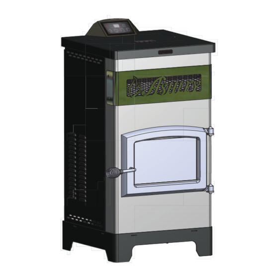
MODEL: AP5770/AP5770I
OWNER'S MANUAL
This unit is not intended to be used as a primary source of heat.
U.S. Stove Company
227 Industrial Park Road, South Pittsburg, TN 37380
FOR TECHNICAL ASSISTANCE:
Certifi ed for installations in the USA
U.S. Environmental Protection Agency
Certified to comply with 2015 particulate
Phone 800-750-2723 www.usstove.com
and Canada.
emissions standards.
852418-1903E
Advertisement
Table of Contents

Related Manuals for U.S. Stove Ashley AP5770

Summary of Contents for U.S. Stove Ashley AP5770
- Page 1 French version is available for download from the U.S. Stove website: http://www.usstove.com/ Version française est disponible pour téléchargement à partir du site U.S. Stove: http://www.usstove.com OWNER’S MANUAL This unit is not intended to be used as a primary source of heat.
- Page 2 Safety Precautions This manual describes the installation and operation of the Ashley, AP5770, AP5770I wood heater. This heater meets the 2015 U.S. Environmental Protection Agency’s crib wood emission limits for wood heaters sold after May 15, 2015. Under specifi c test conditions this heater has been shown to deliver heat at rates ranging from 10,898 to 24,335 Btu/hr. ...
- Page 3 WARRANTY INFORMATION CARD Name__________________________________________ Telephone #: (_____)_____________ City____________________________________________ State_______ Zip_________________ Email Address __________________________________________________________________ Model # of Unit________________________________ Serial #___________________________ Fuel Type: Wood Coal Pellet Gas Other _________________________ Place of Purchase (Retailer)______________________________________________________ City____________________________________________ State_______ Zip_________________ If internet purchase, please list website address___________________________________ Date of Purchase _______________________________________________________________ Alternative Heat Main Heat Source...
- Page 4 Fold Here Fold Here Fold Here PLACE STAMP HERE United States Stove Company P.O. Box 151 South Pittsburg, TN 37380...
-
Page 5: Specifications
SPECIFICATIONS HEATING SPECIFICATIONS Fuel Burn Rate* (lowest setting) 1.5 lbs./hr. (0.5 kg/hr) Burn Time (lowest setting) 40 hrs. (approximate) Hopper Capacity 60 lbs. (55kg) up to 48,000 * Pellet size may effect the actual rate of fuel feed and burn times. Fuel feed rates may vary by as much as 20%. Use PFI listed fuel for best results. DIMENSIONS Height 44.5 in. -
Page 6: Installation Options
INSTALLATION INSTALLATION OPTIONS Read this entire manual before you install and use your pellet stove. Failure to follow instructions may result in property damage, bodily injury, or even death! (See specifi c installation details for clearances and other installation requirements) A Freestanding Unit—supported by pedestal/legs and placed on a non-combustible fl... -
Page 7: Floor Protection
INSTALLATION FLOOR PROTECTION This heater must have a non-combustible fl oor protector (UL1618 ember protection) installed beneath it if the fl oor is of combustible material. The fl oor pad or non-combustible surface should be large enough to cover at least the area under the product and 6 in. - Page 8 INSTALLATION The minimum installation dimensions, of the insert opening, are: 22” (558.8 mm) wide x 24” (609.6 mm) high x 9.17” (233 mm) deep. 5.72 9.17 14.59 43.93 28.17 31.92 23.60 11.00 FIGURE 5 INSERT DIMENSIONS...
- Page 9 INSTALLATION VENTING REQUIREMENTS Install vent at clearances specified by the vent manufacturer. Do not connect the pellet vent to a vent serving any other appliance or stove. Do not install a flue damper in the exhaust venting system of this unit. The following installation guidelines must be followed to ensure conformity with both the safety listing of this stove and to local building codes.
-
Page 10: Vent Termination Clearances
INSTALLATION VENT TERMINATION CLEARANCES: Minimum 4-foot (1.22m) clearance below or beside any door or window that opens. Minimum 1-foot (0.3m) clearance above any door or window that opens. Minimum 3-foot (0.91m) clearance from any adjacent building. Minimum 7-foot (2.13m) clearance from any grade when adjacent to public walkways. Minimum 2-foot (0.61m) clearance above any grass, plants, or other combustible materials. -
Page 11: Through The Wall Installation
INSTALLATION THROUGH THE WALL INSTALLATION ( RECOMMENDED INSTALLATION) Canadian installations must conform to CAN/CSA-B365. To vent the unit through the wall, connect the pipe adapter to the exhaust motor adapter. If the exhaust adapter is at least 18 in.(457mm) above ground level, a straight section of pellet vent pipe can be used through the wall. -
Page 12: Outside Air Supply
INSTALLATION OUTSIDE AIR SUPPLY (optional, unless installing in a mobile home) Adequate ventilation air is required to operate this heater. During operation, the heater draws air for combustion which can be assisted by the installation of outside combustion air inlets. However, certain weather conditions such as icing or use of kitchen exhaust fans may impact and reduce the effectiveness of vents. - Page 13 INSTALLATION PREPARATION Factory packaging must be removed, and some minor assembly work is required prior to installation. Access to the rear of the stove is necessary. The circuit board/control panel must be unpacked and installed in the side fl ashing on the insert or side panel on the freestanding.
-
Page 14: Combustion Air Supply
INSTALLATION COMBUSTION AIR SUPPLY If outdoor combustion air is supplied the heater must be attached to the structure. For a mobile home installation the stove must be connected to an outside source of combustion air. A 2” inside diameter metallic pipe, either fl exible or rigid, may be attached to the inlet at the stove’s rear. A rodent guard (minimum ¼” wire mesh)/ wind hood must be used at the terminus. - Page 15 INSTALLATION WHEN VENT PIPE EXTENDS TO CHIMNEY TOP 1. You will need a pipe length equal to the chimney height (from hearth) plus 6 inches. If outside combustion air is to be used, you will need a pipe length equal to the chimney height plus 12 inches. 2.
- Page 16 INSTALLATION AS A BUILT-IN FIREPLACE The fi gures on this page describe this stoves installation vented into either a special chase built outside an outer wall or a false inside wall. This is especially suited for new construction or remodeling. The equipment compartment (sides and rear of the stove in fi...
-
Page 17: Installation In To A Factory Built (Metal) Fireplace
INSTALLATION INSTALLATION IN TO A FACTORY BUILT (METAL) FIREPLACE When installing into a factory built fi replace, the fi rebox must accept the insert without modifi cation other than removing bolted or screwed together pieces such as smoke shelf/defl ectors, ash lips, screen or door tracks and damper assemblies. These items must be reinstalled to restore the fi... -
Page 18: Panel Controls
CONTROL PANEL PANEL CONTROLS The blowers and automatic fuel supply are controlled from a panel on the top of the AP5770. The control panel functions are a follows. ON/OFF SWITCH (“POWER” BUTTON) • When pushed, the stove will automatically ignite. No other fi re starter is necessary. The igniter will stay on for at least 10 and up to 12 minutes, depending on when Proof of Fire is reached. -
Page 19: Operation
OPERATION DO NOT USE CHEMICALS OR FLUIDS TO START THE FIRE - NEVER USE GASOLINE, GASOLINE-TYPE LANTERN FUEL, KEROSENE, CHARCOAL LIGHTER FLUID, OR SIMILAR LIQUIDS TO START OR “FRESHEN UP” A FIRE IN THIS STOVE. KEEP ALL SUCH LIQUIDS WELL AWAY FROM THE STOVE WHILE IT IS IN USE. ... - Page 20 OPERATION AUTOMATIC IGNITOR Fill hopper and clean burn pot. 1. Press “On/Off” button. Make sure green light comes on. 2. The damper should be completely closed or open no more than ¼ of the way during start-up. This will vary de- pending on your installation and elevation.
-
Page 21: Shutdown Procedure
OPERATION KEEP HOPPER LID CLOSED AT ALL TIMES EXCEPT WHEN REFILLING. DO NOT OVERFILL HOPPER. SHUTDOWN PROCEDURE Turning your stove off is a matter of pressing the “POWER” button on the display board. The green light will turn back to red when the “POWER”... -
Page 22: Maintenance
MAINTENANCE Failure to clean and maintain this unit as indicated can result in poor performance, safety hazards, fire, and even death. Unplug your stove’s electrical cord prior to removing the back panel or opening the exhaust system for any inspection, cleaning, or maintenance work. ... - Page 23 MAINTENANCE DOOR AND GLASS GASKETS nspect the main door and glass window gaskets periodically. The main door may need to be removed to have frayed, broken, or compacted gaskets replaced by your authorized dealer. This unit’s door uses a 5/8” diameter rope gasket. BLOWER MOTORS Clean the air holes on the motors of both the exhaust and distribution blowers annually.
-
Page 24: Troubleshooting Guide
TROUBLE SHOOTING GUIDE When your stove acts out of the ordinary, the fi rst reaction is to call for help. This guide may save time and money by enabling you to solve simple problems yourself. Problems encountered are often the result of only fi ve factors: 1) poor fuel;... - Page 25 TROUBLE SHOOTING GUIDE Display is Flashing “E2” Possible Causes Possible Remedies: (Unplug stove fi rst when possible) Unhook air hose from the air switch and blow through it. 1. Airfl ow switch hose or stove attachment pipes for hose If air fl ows freely, the hose and tube are fi ne. If air will not are blocked.
- Page 26 TROUBLE SHOOTING GUIDE Display is Flashing “E3” Possible Causes Possible Remedies: (Unplug stove fi rst when possible) 1. The hopper is out of pellets Refi ll the hopper. If on the low setting, you may need to close the damp- 2.
- Page 27 TROUBLE SHOOTING GUIDE Display is Flashing “E4” Possible Causes Possible Remedies: (Unplug stove fi rst when possible) 1. The air inlet, burnpot, interior combustion air chambers, Follow all cleaning procedures in the maintenance sec- combustion blower, or exhaust pipe are blocked with ash tion of the owner’s manual.
- Page 28 TROUBLE SHOOTING GUIDE STOVE FEEDS PELLETS, BUT WILL NOT IGNITE Possible Causes Possible Remedies: (Unplug stove fi rst when possible) 1. Air damper open too far for ignition. Push the air damper in closer to the side of the stove for startup.
- Page 29 TROUBLE SHOOTING GUIDE STOVE WILL NOT FEED PELLETS, BUT FUEL FEED LIGHT COMES ON AS DESIGNED Possible Causes Possible Remedies: (Unplug stove fi rst when possible) 1. High limit switch has tripped or is defective. Wait for the stove to cool for about 30 - 45 minutes. Locate the High Limit thermodisc and press the reset button on the back of it.
- Page 30 TROUBLE SHOOTING GUIDE • GLASS “SOOT’S” UP AT A VERY FAST RATE • FLAME IS LAZY, DARK, AND HAS BLACK TIPS • AFTER STOVE HAS BEEN ON FOR A WHILE, THE BURNPOT OVERFILLS Possible Causes Possible Remedies: (Unplug stove fi rst when possible) 1.
-
Page 31: Wiring Diagram
WIRING DIAGRAM... -
Page 32: Parts Diagram
PARTS DIAGRAM... -
Page 33: Parts List
PARTS LIST Part No. Description Qty. 892183 Main Weldment 83538 Shaft Collar - Ignitor Tube 892184 Hopper 892185 Auger Housing Weld. 892186 Plate, Auger Bushing 892187 Auger 891132 Agitator Bushing 892188 Auger Motor Mounting Bracket 892189 Auger Motor Shock Absorber 83917 Plastic Grommet 892190... -
Page 34: Parts Diagram / Parts List
PARTS DIAGRAM / PARTS LIST Door Parts List Part No. Description Qty. 40586 Feed Door 88066 3/4” Round Rope Gasket-Black 55 in 892197 Door Glass 88087 1/8 x 1 Window Gasket w/Adhesive 39 in 892194 Retainer, Bottom, Glass 892195 Retainer, Top,. Glass 83202 Glass Retainer Screw 892196... -
Page 35: How To Order Repair Parts
HOW TO ORDER REPAIR PARTS THIS MANUAL WILL HELP YOU OBTAIN EFFICIENT, DEPENDABLE SERVICE FROM YOUR PELLET STOVE, AND ENABLE YOU TO ORDER REPAIR PARTS COR- RECTLY. KEEP THIS MANUAL IN A SAFE PLACE FOR FUTURE REFERENCE. WHEN WRITING, ALWAYS GIVE THE FULL MODEL NUMBER WHICH IS ON THE NAMEPLATE ATTACHED TO THE HEATER.
Need help?
Do you have a question about the Ashley AP5770 and is the answer not in the manual?
Questions and answers