IAI RCP6S Instruction Manual
Fieldbus communication
Hide thumbs
Also See for RCP6S:
- First step manual (5 pages) ,
- Instruction manual (147 pages) ,
- First step manual (3 pages)

Related Manuals for IAI RCP6S


Summary of Contents for IAI RCP6S
- Page 1 RCP6S Fieldbus Communication Instruction Manual Fouth Edition RCP6S Gateway Controllers RCM-P6PC RCM-P6AC RCM-P6DC Hub Unit Gateway Unit RCM-P6HUB RCM-P6GW (G)
- Page 3 • This Instruction Manual is original. • The product cannot be operated in any way unless expressly specified in this Instruction Manual. IAI shall assume no responsibility for the outcome of any operation not specified herein. • Information contained in this Instruction Manual is subject to change without notice for the purpose of product improvement.
- Page 4 Construction of Instruction Manual for Each Controller Model and This Manual This instruction manual is for the fields communication using RCP6S Gateway Unit, Hub Unit and controllers for RCP6S Gateway. For installation and how to attach conveyance objects, refer to instruction manual for each actuator type.
- Page 5 RCP6S Fieldbus Communication Table of Overall Contents Name for Each Parts and Their Functions In this chapter, explains the name for each parts and their functions. Chapter 1 Specifications Check of Controller In this chapter, explains the specifications, power capacity, model codes, etc.
-
Page 6: Table Of Contents
Specification of Gateway Unit.................. 28 1.2.3 Specification of Hub Unit ..................28 1.2.4 Specification of RCP6S Gateway Controllers............29 1.2.5 Specification of Environment (Built-in Controller/Gateway Unit/Hub Unit/ RCP6S Gateway Controller in Common)..............31 The Calculation of Number of Connectable Axes and Power Capacity....... 32 Specifications for Each Fieldbus .................. - Page 7 RCP6S Fieldbus Communication Chapter 3 Operation ....................75 Basic Operation......................75 3.1.1 Basic Operation Methods ..................75 3.1.2 Relation between Axis Number and PLC Address Domain (Left-Justification Feature) ..................78 Initial Setting......................... 80 3.2.1 Operation Mode Setting (Setting in Gateway Parameter Setting Tool) ....80 3.2.2...
- Page 8 RCP6S Fieldbus Communication Selecting Automatic Current Reduction Feature............178 6.2.1 Process When Feature is Active................179 6.2.2 Caution ........................179 Chapter 7 Absolute Reset ..................181 7.1 Absolute Reset........................ 181 Chapter 8 Parameter ..................... 185 Parameter List ......................186 Detail Explanation of Parameters................191 Servo Adjustment .......................
- Page 9 RCP6S Fieldbus Communication ME0349-4B...
- Page 10 ☆For Gateway Unit (extension): 3) Touch Panel Teaching Instruction Manual (ME0324) Field Network Setting File 4) RCP6S(CR), RCP6SW Instruction Manual for Each Type File (e.g. EDS File) 5) Serial Communication [Modbus] Instruction Manual (ME0162) 6) Instruction manual of each actuator Download it in homepage (http://www.iai-robot.co.jp/)
- Page 11 Axis No.9 Axis No.8 Note When an actuator is to connected to the controller for RCP6S Gateway, make sure to connect an actuator of the model code stated on the controller front panel. Operation will not be performed correctly if an actuator not indicated is connected.
- Page 12 RCP6S Fieldbus Communication Step 5 Operate Unit How you should look in the instruction manuals will differ depending on the operation modes and control methods you choose. Establish the settings for your control format needs. ● For Fieldbus Communication Control 3.1.
-
Page 13: Safety Guide
RCP6S Fieldbus Communication Safety Guide “Safety Guide” has been written to use the machine safely and so prevent personal injury or property damage beforehand. Make sure to read it before the operation of this product. Safety Precautions for Our Products The common safety precautions for the use of any of our robots in each operation. - Page 14 RCP6S Fieldbus Communication Operation Description Description Transportation ● When carrying a heavy object, do the work with two or more persons or utilize equipment such as crane. ● When the work is carried out with 2 or more persons, make it clear who is to be the leader and who to be the follower(s) and communicate well with each other to ensure the safety of the workers.
- Page 15 RCP6S Fieldbus Communication Operation Description Description Installation (2) Cable Wiring and Start ● Use our company’s genuine cables for connecting between the actuator and controller, and for the teaching tool. ● Do not scratch on the cable. Do not bend it forcibly. Do not pull it. Do not coil it around.
- Page 16 RCP6S Fieldbus Communication Operation Description Description Installation (4) Safety Measures and Start ● When the work is carried out with 2 or more persons, make it clear who is to be the leader and who to be the follower(s) and communicate well with each other to ensure the safety of the workers.
- Page 17 RCP6S Fieldbus Communication Operation Description Description Trial ● When the work is carried out with 2 or more persons, make it clear who Operation is to be the leader and who to be the follower(s) and communicate well with each other to ensure the safety of the workers.
- Page 18 RCP6S Fieldbus Communication Operation Description Description Maintenance ● When the work is carried out with 2 or more persons, make it clear who is to be the leader and who to be the follower(s) and communicate well Inspection with each other to ensure the safety of the workers.
- Page 19 RCP6S Fieldbus Communication Alert Indication The safety precautions are divided into “Danger”, “Warning”, “Caution” and “Notice” according to the warning level, as follows, and described in the Instruction Manual for each model. Level Degree of Danger and Damage Symbol This indicates an imminently hazardous situation which, if the...
-
Page 20: Precautions In Operation
RCP6S Fieldbus Communication ■Precautions in Operation■ 1. Make sure to follow the usage condition, environment and specification range of the product. In case it is not secured, it may cause a drop in performance or malfunction of the product. 2. Use an appropriate teaching tool. - Page 21 RCP6S Fieldbus Communication 7. Limitations on operation of rotary actuator in index mode Rotary actuators of 360° specification can select the normal mode for finite rotations or the index mode enabling multi-rotation control by using parameter No.79 “Rotary Axis Mode Selection”.
- Page 22 11. Caution when RCP6S Gateway Controller is Connected When RCM-P6DC or RCM-P6DC which is a controller for RCP6S Gateway is to be connected, the version of the gateway unit and the hub unit needs to be V0004 or later for both units.
-
Page 23: International Standards Compliances
This product comply with the following international standards: Refer to Overseas Standard Compliance Manual (ME0287) for more detailed information. Device RoHS Directive CE Marking Gateway Unit ○ ○ ○ Hub Unit ○ ○ ○ RCP6S Gateway Controllers ○ ○ ○ ME0349-4B... -
Page 24: Name For Each Parts And Their Functions
RCP6S Fieldbus Communication ■Name for Each Parts and Their Functions■ 1. Controller Unit in RCP6S (Built-in Controller Type) 2) Status Indicator LED 3) Communication (SIO) Connector 1) Power / Communication line Connector 1) Power / Communication line Connector [Refer to Chapter 2] It is a connector that the gateway unit, hub unit or PLC unit etc. - Page 25 RCP6S Fieldbus Communication 2. RCP6S Gateway Unit 8) Fieldbus Connector 7) System I/O 9) Status Display LED Connector 6) Operation Mode LED1: SYS Setting Switch LED2: AUTO 5) SIO Connector LED3: EMG 4) USB Connector LED4: T. ERR LED5: C. ERR...
- Page 26 RCP6S Fieldbus Communication 9) Status Display LED It shows the status of gateway unit. : Illuminating Symbol Display Color and Operation Status System Status LED1 Ready ( Green), Alarm ( Red) Operation Mode (AUTO/MANU) Status LED2 AUTO Automatic Operation (AUTO) Mode (...
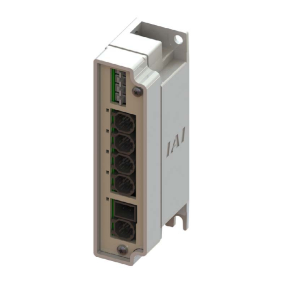
- Page 27 RCP6S Fieldbus Communication 3. RCP6S Hub Unit 6) Breake Release Swicth AXIS3 5) Breake Release Swicth AXIS2 4) Breake Release Swicth AXIS1 7) RCP6S Connector AXIS3 3) Breake Release Swicth AXIS0 8) RCP6S Connector AXIS2 9) RCP6S Connector AXIS1 10) RCP6S Connector AXIS0...
- Page 28 RCP6S Fieldbus Communication 11) Axis Status Display LED It shows the status of hub unit and connected actuator. : Illuminating ×: OFF ✰: Flashing Symbol Display Color and Operation Status Axis No.0 to 3 Status LED1 AX3 STS Servo OFF (× OFF)
- Page 29 It is a connector to connect such as a teaching pendant or PC. Refer to Chapter 2 Wiring for details for such as connector codes and pin assignments etc. 4) Status Display LED It shows the status of the RCP6S Gateway controllers. : Illuminating ×: OFF Symbol...
-
Page 30: Actuator Axes
RCP6S Fieldbus Communication ■Actuator Axes■ Refer to the pictures below for the actuator axes that can be controlled. 0 defines the home position, and items in ( ) are for the home-reversed type (option). Caution : There are some actuators that are not applicable to the origin reversed type. - Page 31 RCP6S Fieldbus Communication (6) Rotary type (330 ° Rotation Specification) (Multi-rotation Specification) The directions of positive and negative will be opposite for the home-reversed type in the multi-rotation type. ME0349-4B...
- Page 32 RCP6S Fieldbus Communication ME0349-4B...
-
Page 33: Chapter 1 Specifications Check
Specifications Check 1.1 Product Check 1.1.1 Parts The standard configuration of this product is comprised of the following parts. If you find any faulty or missing parts, contact your local IAI distributor. Part Name Model and Picture Number Remarks Refer to each instruction manual Actuator Main Body of an actuator. - Page 34 Refer to “1.1.4 How to read the RCM-P6HUB Hub Unit model plate”, “1.1.5 How to read the model”. Refer to “1.1.4 How to read the RCM-P6PC RCP6S Gateway model plate”, “1.1.5 How to read RCM-P6AC Controllers the model”. RCM-P6DC RCM-CV-APCS...
-
Page 35: Teaching Tool
RCP6S Fieldbus Communication 1.1.2 Teaching Tool A teaching tool such as PC software is necessary when performing the setup for position setting, parameter setting, etc. that can only be done on the teaching tool. Please prepare either of the following teaching tools. -
Page 36: Instruction Manuals Related To This Product, Which Are Contained In The Instruction Manual (Dvd)
1.1.3 Instruction Manuals Related to This Product, which are Contained in the Instruction Manual (DVD). Part Name Model Instruction Manual for the RCP6S Fieldbus Communication (This manual) ME0349 Instruction Manual for the Serial Communication [for Modbus] ME0162 Instruction Manual for the RCP6(S)(CR) Slider Type... -
Page 37: How To Read The Model Nameplate
RCP6S Fieldbus Communication 1.1.4 How to Read the Model Nameplate * Refer to the each instruction manual of the label of RCP6S built-in controller gateway unit. [1] Gateway Unit Model code Model RCM-P6GW-CC SER NO. 12345678 00 Serial number Input DC24V , 44.6A... -
Page 38: How To Read The Model
RCP6S Fieldbus Communication 1.1.5 How to Read the Model * Refer to the each instruction manual of the label of RCP6S built-in controller gateway unit. [1] Gateway Unit RCM − P6GW − CC CC : CC-Link Connection Type DV : DeviceNet Connection Type... -
Page 39: List Of Basic Specifications
Corresponding Encoder Battery-less absolute encoder Resolution 8192pulse/rev Between gateway unit and hub: 10m max. Cable Length Between gateway unit and RCP6S actuator: 20m max. Serial Communication Interface RS485: 2CH (based on Modbus protocol RTU/ASCII) (SIO Port) Only 1CH is in conformity with ASCII Speed: 9.6 to 230.4Kbps Fieldbus connection (Note) Connection of gateway unit is necessary separately. -
Page 40: Specification Of Gateway Unit
Tool Connection USB connector : USB 1ch System I/O connector: External brake release signal input (24V DC) Electromagnetic Brake Compulsory * Used only when RCP6S connected directly to gateway unit. Invalid when hub Release Feature connected. Protection Function against Electric... -
Page 41: Specification Of Rcp6S Gateway Controllers
RCP6S Fieldbus Communication 1.2.4 Specification of RCP6S Gateway Controllers RCM-P6PC [1] Pulse Motor Type Specification Item Details of Specifications Number of Controlled Axes 1-axis Controller Power-supply DC24V ± 10% Applicable Motor Rated Current Rated at 1.2A, Rated at 0.4A 0.3A (It is necessary to have 0.7A for 0.2s at brake release Control Power Capacity when RCP6 actuator is equipped with a brake.) - Page 42 RCP6S Fieldbus Communication RCM-P6AC [2] Servo Motor Type Specification Item Details of Specifications Number of Controlled Axes 1-axis Controller Power-supply DC24V ± 10% Control Power Capacity 0.3A Rated at 0.8A, 4.6A max. Rated at 1.0A, 6.4A max. Rated at 1.3A, 6.4A max.
-
Page 43: Specification Of Environment (Built-In Controller/Gateway Unit/Hub Unit/Rcp6S Gateway Controller In Common)
External Dimensions 30W × 115H × 58D ( 66.5D) Dimension described in brackets is for DIN rail type 1.2.5 Specification of Environment (Built-in Controller/Gateway Unit/Hub Unit/ RCP6S Gateway Controller in Common) Specification Item Details of Specifications Surrounding Air Temperature 0 to 40°C... -
Page 44: The Calculation Of Number Of Connectable Axes And Power Capacity
24V DC power supply unit or a short-circuit of the power supply. • Rated Breaking Current > Short-circuit Current = Primary Power Supply Capacity / Power Voltage • (Reference) In-rush Current of IAI Power Supply Unit PS241 = 50 to 60A, 3msec ME0349-4B... -
Page 45: Specifications For Each Fieldbus
RCP6S Fieldbus Communication 1.4 Specifications for Each Fieldbus 1.4.1 Specifications of DeviceNet Interface Item Specification Communication Protocol DeviceNet2.0 Group 2 dedicated server Network-powered insulation node Baud Rate Automatically follows the master Communication System Master-slave system (Polling) Number of Occupied Channels Refer to 3.4.1 PLC Address Construction by each Operation Mode... -
Page 46: Specifications Of Profibus-Dp Interface
RCP6S Fieldbus Communication 1.4.3 Specifications of PROFIBUS-DP Interface Item Specification Communication Protocol PROFIBUS-DP Baud Rate Automatically follows the master Communication System Hybrid System (Master-slave system or token passing system) Number of Occupied Stations Refer to 3.4.1 PLC Address Construction by Each Operation Mode Communication Cable Length MAX. -
Page 47: Specifications Of Profinet-Io Interface
RCP6S Fieldbus Communication 1.4.6 Specifications of PROFINET-IO Interface Item Specification Communication Protocol IEC61158 (IEEE802.3), IEC61784 Baud Rate 100Mbps Number of Occupied Bytes 3.4.1 PLC Address Construction by each Operation Mode Communication Cable Length Distance between each segment: 100m Max. Number of Connection Follows master unit Available Node Addresses for Setting 0.0.0.0 to 255.255.255.255... -
Page 48: External Dimensions
RCP6S Fieldbus Communication 1.5 External Dimensions 1.5.1 Gateway Unit Fixed Screws Type and Attachment DIN Rail Type ME0349-4B... -
Page 49: Hub Unit
RCP6S Fieldbus Communication 1.5.2 Hub Unit [1] Fixed Screws Type 19.5 19.5 [2] Attachment DIN Rail Type ME0349-4B... -
Page 50: Rcp6S Gateway Controller
RCP6S Fieldbus Communication 1.5.3 RCP6S Gateway Controller Dimensions for RCM-P6PC, RCM-P6AC and RCM-P6DC should be the same. [1] Fixed Screws Type Attachment DIN Rail Type ME0349-4B... -
Page 51: Installation And Storage Environment
RCP6S Fieldbus Communication 1.6 Installation and Storage Environment This product is capable for use in the environment of pollution degree 2 or equivalent. *1 Pollution Degree 2 : Environment that may cause non-conductive pollution or transient conductive pollution by frost (IEC60664-1) [1] Installation Environment Do not use this product in the following environment. -
Page 52: Noise Elimination And Mounting Method
RCP6S Fieldbus Communication 1.7 Noise Elimination and Mounting Method (1) Noise Elimination Grounding (Frame Ground) Connect the ground line to the Gateway Unit FG terminal block on the controller unit. Put a tool such as a screwdriver into the square slot to open the opening to connect the line. - Page 53 RCP6S Fieldbus Communication (4) Heat Radiation and Installation Design and Build the system considering the size of the controller box, location of the controller and cooling factors to keep the surrounding temperature around the controller below 40°C. To fix the units in the control box, use the attachment holes on top and bottom of the unit for the screw fixed type, and use the DIN rails for the DIN rail fixed type.
- Page 54 RCP6S Fieldbus Communication RCP6S Gateway Controllers (RCM-P6PC/RCM-P6AC/RCM-P6DC) 10mm or more 10mm 10mm 10mm or more or more or more 100mm or more 10mm or more ME0349-4B...
-
Page 55: Chapter 2 Wiring
A hub unit is capable for four axes of RCP6S actuators connected to one unit, and by connecting hub units to all of four channels of the gateway unit, 16 axes of the RCP6S actuators can be connected at the maximum. - Page 56 Axis No.9 Axis No.8 Note When an actuator is to connected to the controller for RCP6S Gateway, make sure to connect an actuator of the model code stated on the controller front panel. Operation will not be performed correctly if an actuator not indicated is connected.
-
Page 57: Wiring Diagram (Connection Of Construction Devices)
RCM-CV-APCS Caution: Turn the power off at the gateway unit before putting in or taking out a connector on PC software or a teaching pendant from the gateway unit, RCP6S built-in controller or RCP6S Gateway controller. Putting in or taking out a connect while the power is kept on may cause malfunction. -
Page 58: Circuit Diagram
1) Example of wiring to drive an actuator using only emergency stop input from a teaching tool Teaching Tool Operation Stop Switch Gateway Unit System I/O Connector Connector RCP6S Actuator or RCP6S Gateway Controllers Teaching Built in Drive Cutoff Circuit Dedicated Tool Connection Hub Unit (MAX.16 units) - Page 59 In case a hub unit is not to be connected, connect an actuator or a controller for RCP6S GW to the axis control connector. Note 1 RCM-P6GW : When there is nothing plugged in the SIO connector, S1 and S2 are short-circuited inside the controller.
- Page 60 Connector SIO Connector Gateway Axis (Note 1) Unit Control Connector RCP6S Axis Power Supply Connector RCP6S Actuator RCP6S Actuators アクチュエータ (Note 3) (最大 16 台) (MAX. 16 units) (MAX. 16units) Emergency Stop Detection Circuit Unit 1 Drive Cutoff Connector (Note 2)
- Page 61 ■ Connection among Gateway Unit, Hub Unit and RCP6S In order to operate the RCP6S actuator with each fieldbus, it is necessary to connect it to the gateway unit or the hub unit. Use RCP6S connection cable in case of connecting to either unit.
- Page 62 Connector: DF62C-13S-2.2C Note 1 The maximum length should be 10m between the gateway and hub unit. Not e2 The maximum length should be 20m from the gateway unit to RCP6S regardless of a hub unit is used or not used.
- Page 63 Control Connector Connector Connect a controller for RCP6S Gateway to the hub unit (or a gateway unit) and connect a RCP5 or 6 actuator on the further end. [E] When connection is established with a pulse motor type actuator (RCP2 to 4)
- Page 64 Control Connector Connector Connect a controller for RCP6S Gateway (RCM-P6AC) to the hub unit (or a gateway unit) and connect a RCA or RCA2 actuator on the further end via a connector conversion unit. [G] When connection is established with a brushless DC electric motor type actuator (RCD)
- Page 65 Use this connector conversion unit in case of actuators not being able to connect to the connection cable for RCP6S Gateway in 5) in the previous page in order to convert it to the existing controller connector (PADP-24V-1-S) and connect the connection cables to each actuator.
- Page 66 BK_AX8 Axis No.8 Brake Release Input Circuit BK_AX12 Axis No.12 Brake Release Input Circuit 0V is in common with the control power supply. Brakes should be available for release if the control power is supplied to RCP6S Gateway Unit. ME0349-4B...
- Page 67 1) DeviceNet Type Terminal Resistance is required to be mounted on the terminal. Terminal Resistance Terminal Resistance Master Unit Slave Devices RCP6S GW-DeviceNet Type 121Ω 121Ω CAN_H CAN_H CAN_H Drain Drain Drain...
- Page 68 RCP6S Fieldbus Communication 4) EtherNet/IP Type Switching Hub Master Unit Slave Devices RCP6S GW Unit EtherNet/IP Type Ethernet Straight Cable, Category 5e or more Double shielded cable braided with aluminum foil recommended 5) EtherCAT Type RCP6S GW Slave Devices Master Unit...
-
Page 69: Wiring Method (Gateway Unit)
RCP6S Fieldbus Communication 2.3 Wiring Method (Gateway Unit) 2.3.1 Wiring to Power Input Connector The power cables of the gateway unit are to be connected to the motor power supply connector and the control power supply connector on the main body. - Page 70 RCP6S Fieldbus Communication [2] Control Power Supply Connector Connector model: SPT2.5/3-H-5.0 (Manufactured by PHOENIX CONTACT) Signal Pin No. Description Applicable cable diameter Name Control Power Supply 24V Input KIV3.5 to 0.5mm (AWG12 to 20) 0V Input Frame Ground KIV3.5 to 2.0mm...
-
Page 71: Wiring Layout Of System I/O Connector
RCP6S Fieldbus Communication 2.3.2 Wiring Layout of System I/O Connector The connector consists of the emergency stop input for the whole controller, changeover of the operation modes (AUTO/MANU) externally and the external brake release input (used only when actuator connected directly to gateway unit). -
Page 72: Wiring Of Drive-Source Cutoff Connector
RCP6S Fieldbus Communication 2.3.3 Wiring of Drive-source Cutoff Connector It is a connector to connect the external drive cutoff relay to 24V DC input from the motor power supply connector. Output 24V DC externally from MPO, and put it back from MPI to GW unit via the relay contact. -
Page 73: Connection With The Actuator/Hub
Diameter Front view of connector on gateway unit side Cable dedicated for IAI products Motor Power Supply 24V DC Motor Power Supply 24V DC Motor Power Supply 24V DC (2) Axis Control Connector It is a connector to supply power and control signals (24V DC control power supply, 24V DC motor power supply, communication line, brake release signal and emergency stop status) from the gateway to hub unit or actuator. -
Page 74: Connection Of Teaching Tool (Sio Connector, Usb Connector)
RCP6S Fieldbus Communication 2.3.5 Connection of Teaching Tool (SIO Connector, USB Connector) Connect an teaching tool such as the PC software. Connection of either RS485 or USB is available. Apply the enclosed dummy plug (DP-5) to the teaching connector when Operation Mode Setting Switch is set to AUTO in safety categories complied type (RCM-P6GWG). - Page 75 RCP6S Fieldbus Communication [2] USB Connector USB Connector Model Remarks Gateway Unit Side 51387-0530 Manufactured by MOLEX Front view of Signal connector on Pin No. Description Applicable Cable Diameter gateway unit side Name Communication Data - Communication Data + USB Cable...
-
Page 76: Wiring Of Fieldbus Connector
RCP6S Fieldbus Communication 2.3.6 Wiring of Fieldbus Connector Refer to the instruction manuals of the each fieldbus master unit and mounted PLC for details. DeviceNet Type RD (V+) WT (CAN H) Shield BL (CAN L) BK (V - ) Connector Name DeviceNet Connector... - Page 77 RCP6S Fieldbus Communication CC-Link Type Shield (SLD) YW (DG) WT (DB) BL (DA) Connector Name CC-Link Connector Enclosed in standard package Cable Side MSTB2.5/5-STF-5.08 AU Manufactured by PHOENIX CONTACT Gateway Unit MSTB2.5/5-GF-5.08 AU Side Signal Name Applicable Description (Color) Cable Diameter...
- Page 78 RCP6S Fieldbus Communication PROFIBUS-DP Type Use the type A cable for PROFIBUS-DP (EN5017). Red B line (Positive side) Green A line (Negative side) Cable Shield Connector Name PROFIBUS-DP Connector Cable Side 9-Pin D Sub Connector (Male) Please prepare separately Gateway Unit...
- Page 79 RCP6S Fieldbus Communication 4) EtherNet/IP Type Connector Name EtherNet/IP Connector Cable Side 8P8C Modular Plug Please prepare separately Gateway Unit 8P8C Modular Jack Side Signal Name Applicable Cable Pin No. Description (Color) Diameter Data Sending + Data Sending - For EtherNet cable,...
- Page 80 RCP6S Fieldbus Communication PROFINET-IO Type Connector Name PROFINET Connector Cable Side 8P8C Modular Plug Please prepare separately Gateway Unit 8P8C Modular Jack Side Signal Name Applicable Cable Pin No. Description (Color) Diameter Data Sending + Data Sending - For EtherNet cable,...
-
Page 81: Wiring Method (Hub Unit)
Diameter Front view of connector on hub unit side Cable dedicated for IAI products Motor Power Supply 24V DC Motor Power Supply 24V DC Motor Power Supply 24V DC (2) Hub Control Connector It is a connector to supply power and control signals (24V DC control power supply, communication line, brake release signal and emergency stop status) from the gateway to hub unit. -
Page 82: Connection With The Actuator
Brake Release EMGS Emergency Stop Status Serial Communication Line For AM_SD + Automonitor + Cable dedicated for IAI products CT_SD + Control Serial Communication Line + Motor Power Supply 24V DC Motor Power Supply 24V DC Frame Ground Disconnected 2.4.3 Brake Release Switch Four units of compulsory brake release switch are equipped, which can be operated at hand. -
Page 83: Wiring Method (Rcp6S Gateway Controllers)
It is a connector to supply power and send control signals (control power 24V DC, motor power 24DC, communication line, brake release signal and emergency stop status) from the gateway unit or hub unit to controllers for RCP6S Gateway. Connector Name... -
Page 84: Connection With The Actuator/ Connector Conversion Unit
It is a connector to supply power and send control signals (control power 24V DC, motor power 24V DC, communication line, brake release signal and emergency stop status) from the controllers for RCP6S Gateway to actuators or connector conversion units. Connector Name... -
Page 85: Connection Of Teaching Tool
2.5.3 Connection of Teaching Tool Connect an teaching tool such as the PC software. SIO Connector Teaching pendant, PC software connector. Front view of connector on RCP6S gateway controller side Connector Name SIO Connector Remarks Cable Side miniDIN 8pin Manufactured by... - Page 86 RCP6S Fieldbus Communication ME0349-4B...
-
Page 87: Chapter 3 Operation
It is available to have a controller for RCP6S Gateway (RCM-P6PC, RCM-P6AC or RCM-P6DC) instead of RCP6S actuator connected to a hub unit or a gateway unit and connect an actuator of RCP2 to 6, RCA/RCA2 and RCD. In this case, the way to control the operation should be the same unless otherwise specified. - Page 88 [Refer to the instruction manuals for the master unit and PLC] [5] Link to Network 1) Put the operation mode setting switch on the front panel of RCP6S gateway unit to AUTO side and reboot the power. (By putting to AUTO, Fieldbus line activates.)
- Page 89 RCP6S 3.1.1 Fieldbus Communication ● Operation Mode Available 6 types of operation modes are available to select from. The settings are to be established with Gateway Parameter Setting Tool. Shown below are the outline. Operation Mode Contents Overview Simple Direct...
-
Page 90: Left-Justification Feature
RCP6S Fieldbus Communication 3.1.2 Relation between Axis Number and PLC Address Domain (Left-Justification Feature) There are axis numbers allocated in advance on the gateway unit slot and the hub unit slot. The relation between the axis number and the PLC address domain differs as stated below depending on the fieldbus I/O domain left-justification setting feature (hereafter stated as the left-justification setting feature). - Page 91 RCP6S 3.1.2 Fieldbus Communication (2) When Left-Justification Setting Feature is set “Valid (without Alarm)” or “Valid (with Alarm) The PLC address domain of the axes set for left-justification should be justified to the left. (Example for Connection 1) When Axis No. 5, 6, 7 and 11 are set to be left-justified as Axis No.
-
Page 92: Initial Setting
Make sure the system I/O connector wires and operation mode setting switch are in MANU condition when having the setting done. [Refer to 2. RCP6S Gateway Unit 6), 7)] 3.2.1 Operation Mode Setting (Setting in Gateway Parameter Setting Tool) - Page 93 Main windows (Initial condition) [Step 3] Reading is started from RCP6S GW to PC. Click on the “Read” button and a confirmation window appears. Click on the “Yes (Y)” button. If the writing is finished in normal condition, writing complete window appears. Click “OK”.
- Page 94 3.2.1 Fieldbus Communication [Step 4] The parameters input to RCP6S GW are listed as shown below. Indicate the Fieldbus node addresses (station) in RCP6S GW in Address. Caution: In the following slave, set the value the number of occupied station is added to the current station number.
- Page 95 RCP6S 3.2.1 Fieldbus Communication [Step 6] To be conducted for PROFINET-IO type (If not applied, go to Step 7) If parameters are read (Step 3) from MCON to the PC in PROFINET-IO Type, the occupation information will be displayed on the center left of the main screen and MAC address on the right bottom.
- Page 96 RCP6S 3.2.1 Fieldbus Communication [Step 8] Click on Setting in Menu and select Specialty Parameter. As GW Parameter Setting window opens, select GWmode Select. [Step 9] Select invalid when the left-justification setting is not to be used. When the left-justification setting is to be used, select valid (without alarm) or valid (with alarm) in the fieldbus I/O domain left-justification setting in GWmode Select.
- Page 97 RCP6S 3.2.1 Fieldbus Communication [Step 10] When Using Left-Justification Setting Feature (Go to Step 11 when not to be used) (Example for Connection) When Axis No. 5, 6, 7 and 11 are not connected; Teaching Before Left-Justification Setting PLC Address Area...
- Page 98 3.2.1 Fieldbus Communication [Step 11] Write the edited operation mode setting parameters to RCP6S GW. Once ”Write” button in the figure below is pressed, the confirmation message window appears. Click on “Yes (Y)” button. If the writing is finished in normal condition, writing complete window appears.
-
Page 99: Parameter Settings (Setting On Rc Pc Software)
RCP6S Fieldbus Communication 3.2.2 Parameter Settings Setting on RC PC Software Parameter data should be set appropriately according to the applicaiton requirements. Parameters are variables to be set to meet the use of the controller in the similar way as settings of the ringtone and silent mode of a cell phone and settings of clocks and calendars. -
Page 100: Setting Of Position Data
RCP6S Fieldbus Communication 3.3 Setting of Position Data The values in the position table can be set as shown below. In the case that only positioning is necessary, all you have to do is to input the position data, and nothing else is required as long as the indication of acceleration and deceleration is needed. - Page 101 RCP6S Fieldbus Communication 3) Velocity [mm/s]····· Set the velocity in the operation. Do not attempt to input a value more than the maximum velocity or less than the minimum velocity Minimum velocity [mm/s] = Lead length [mm] / Number of encoder pulse (8192) / 0.001 [sec] 4) Acceleration [G] ···Set the acceleration at start.
- Page 102 This feature is used to monitor the load current and judge whether the operation is good or not in such an operation as press fitting in pressing. For RCP6S and This feature is limited only to the pulse motor type actuators. RCM-P6PC only Set to 0 for the servo motor type and brushless DC motor type actuators.
- Page 103 RCP6S Fieldbus Communication 11) Acceleration/deceleration mode ········ Select a proper acceleration/deceleration pattern depending on the load. Acceleration/Deceleration Operation value Pattern Velocity Trapezoid Time Velocity S-shaped Motion (Refer to Caution at S-shaped Motion) Time Set the S-motion rate with parameter No.56.
- Page 104 Transported Load······ Register 4 types of load weights with using the smart tuning, and choose the number from the registered numbers (0 to 3) that is to be used. For RCP6S and From the numbers (load weights) registered in this section, the RCM-P6PC only shortest tact time function calculates the optimum speed and acceleration/deceleration.
- Page 105 Time setting is to be conducted in Parameter No. 36 to 38 Automatic Servo-off Delay Time 1 to 3, and three types of time are available to select. Selection is available from 0 to 3 for the RCP6S, RCM-P6AC and RCM-P6DC. Selection is available from 0 to 7 for RCM-P6PC. However, selection should be made from 0 to 3 in case an actuator equipped with the high-resolution battery-less absolute encoder is connected.
- Page 106 (5) If the vibration frequency setting is low, the takt time may become long. The value below approximately 6Hz makes the positioning finishing to take more than 150ms. This feature is limited only to RCM-P6PC. Set to 0 for RCP6S, RCM-P6AC and RCM-P6DC. ME0349-4B...
-
Page 107: Fieldbus Type Address Map
3.4.1 PLC Address Construction by Each Operation Mode The address domain to be occupied differs depending on the operation mode. PLC Output → RCP6S GW Input (n is PLC output top word address to RCP6S GW) (Note 1) Simple Direct... - Page 108 RCP6S 3.4.1 Fieldbus Communication RCP6S GW Output → PLC Input (n is PLC input top word address from RCP6S GW) (Note 1) Simple Direct Positioner 1 Direct Positioner 2 Positioner 3 Positioner 5 Mode Mode Indication Mode Mode Mode Details...
-
Page 109: Gateway Control Signals (Common For All Operation Modes)
Gateway Control Signals (Common for All Operation Modes) When operating the system with Fieldbus, the axes are controlled via Gateway of RCP6S. The top 2 words of input and output in each operation mode are the signals gateway control and status monitoring. - Page 110 RCP6S 3.4.2 Fieldbus Communication (2) List for Input and Output Signal (ON = Applicable bit is “1”, OFF = Applicable bit is “0”) Signal Type Symbol Description Details Operation control with communication is available – while it is ON –...
- Page 111 RCP6S 3.4.2 Fieldbus Communication (ON = Applicable bit is “1”, OFF = Applicable bit is “0”) Signal Type Symbol Description Details This signal turns ON when Gateway is in normal – operation. This signal turns ON if the ERR-C occurred during...
-
Page 112: Control Signals For Simple Direct Mode
PIO pattern selection × (1) PLC Address Composition (m is PLC input and output top word address for each axis number) PLC → RCP6S GW (PLC Output) RCP6S GW → PLC (PLC Input) Target Position m to m+1 Current Position m to m+1 Completed Position No. - Page 113 RCP6S 3.4.3 Fieldbus Communication (2) Input and Output Signal Assignment for each Axis The I/O signals for each axis consists of 4-word for each I/O bit register. ● The control signals and status signals are ON/OFF signals in units of bit.
- Page 114 RCP6S 3.4.3 Fieldbus Communication PLC Input (m is PLC input top word address for each axis number) 1 word = 16 bit Address m b15 b14 b13 b12 Current Position (Lower word) Address m+1 b15 b14 b13 b12 Current Position (Upper word) (Note) If the target position is a negative value, it is indicated by a two’s complement.
- Page 115 RCP6S 3.4.3 Fieldbus Communication (3) I/O signal assignment (ON = Applicable bit is “1”, OFF = Applicable bit is “0”) Signal Type Symbol Description Details 32-bit signed integer indicating the current position Unit: 0.01mm Available range for Setting: -999999 to 999999...
- Page 116 RCP6S 3.4.3 Fieldbus Communication (ON = Applicable bit is “1”, OFF = Applicable bit is “0”) Signal Type Symbol Description Details 32-bit signed integer indicating the current position Unit: 0.01mm Current 32 bits – (Example) If +10.23mm, input 000003FF (1023 in 3.7.2...
-
Page 117: Control Signals For Positioner 1 Mode
PIO pattern selection × (1) PLC Address Composition (m is PLC input and output top word address for each axis number) PLC → RCP6S GW (PLC Output) RCP6S GW → PLC (PLC Input) Cannot be used. m to m+1 Current Position m to m+1 Completed Position No. - Page 118 RCP6S 3.4.4 Fieldbus Communication (2) Input and Output Signal Assignment for each Axis The I/O signals for each axis consists of 4-word for each I/O bit register. ● The control signals and status signals are ON/OFF signals in units of bit.
- Page 119 RCP6S 3.4.4 Fieldbus Communication PLC Input (m is PLC input top word address for each axis number) 1 word = 16 bit Address m b15 b14 b13 b12 Current Position (Lower word) Address m+1 b15 b14 b13 b12 Current Position (Upper word) (Note) If the target position is a negative value, it is indicated by a two’s complement.
- Page 120 RCP6S 3.4.4 Fieldbus Communication (3) I/O signal assignment (ON = Applicable bit is “1”, OFF = Applicable bit is “0”) Signal Type Symbol Description Details 16-bit integer Available range for Setting: 0 to 767 To operate, it is necessary to have the position data...
- Page 121 RCP6S 3.4.4 Fieldbus Communication (ON = Applicable bit is “1”, OFF = Applicable bit is “0”) Signal Type Symbol Description Details 32-bit signed integer indicating the current position Unit: 0.01mm Current 32 bits – (Example) If +10.23mm, input 000003FF (1023 in 3.7.2...
-
Page 122: Control Signals For Direct Indication Mode
PIO pattern selection × (1) PLC Address Composition (m is PLC input and output top word address for each axis number) PLC → RCP6S GW (PLC Output) RCP6S GW → PLC (PLC Input) Target Position m to m+1 Current Position... - Page 123 RCP6S 3.4.5 Fieldbus Communication (2) Input and Output Signal Assignment for each Axis The I/O signals for each axis consists of 8-word for each I/O bit register. ● The control signals and status signals are ON/OFF signals in units of bit.
- Page 124 RCP6S 3.4.5 Fieldbus Communication PLC Output (m is PLC output top word address for each axis number) 1 word = 16 bit Address m b15 b14 b13 b12 Target Position (Lower word) Address m+1 b15 b14 b13 b12 Target Position (Upper word) (Note) If the target position is a negative value, it is input by a two’s complement.
- Page 125 RCP6S 3.4.5 Fieldbus Communication PLC Input (m is PLC input top word address for each axis number) 1 word = 16 bit Address m b15 b14 b13 b12 Current Position (Lower word) Address m+1 b15 b14 b13 b12 Current Position (Upper word) (Note) If the target position is a negative value, it is output by a two’s complement.
- Page 126 RCP6S 3.4.5 Fieldbus Communication (3) I/O signal assignment (ON = Applicable bit is “1”, OFF = Applicable bit is “0”) Signal Type Symbol Description Details 32-bit signed integer indicating the current position Unit: 0.01mm Available range for Setting: -999999 to 999999...
- Page 127 ON: Movement toward home position, OFF: Stop Jog-speed/inch-distance switching Control OFF : Use the setting values of Parameter No.26 Signal JOG Speed and No.48 Inching Distance in RCP6S [11] JVEL 3.7.1 ON : Use the setting values of Parameter No.47 JOG Speed 2 and No.49 Inching Distance in...
- Page 128 RCP6S 3.4.5 Fieldbus Communication (ON = Applicable bit is “1”, OFF = Applicable bit is “0”) Signal Type Symbol Description Details 32-bit signed integer indicating the current position Unit: 0.01mm Current – (Example) If 10.23mm, input 000003FF (1023 in 3.7.3...
-
Page 129: Control Signals For Positioner 2 Mode
PIO pattern selection × (1) PLC Address Composition (m is PLC input and output top word address for each axis number) PLC → RCP6S GW (PLC Output) RCP6S GW → PLC (PLC Input) Completion Position No. Specified Position No. (Simple Alarm Code) - Page 130 RCP6S 3.4.6 Fieldbus Communication (2) Input and Output Signal Assignment for each Axis The I/O signals for each axis consists of 2-word for each I/O bit register. ● The control signals and status signals are ON/OFF signals in units of bit.
- Page 131 RCP6S 3.4.6 Fieldbus Communication (3) I/O signal assignment (ON = Applicable bit is “1”, OFF = Applicable bit is “0”) Signal Type Symbol Description Details 16-bit integer Available range for Setting: 0 to 767 To operate, it is necessary to have the position data...
- Page 132 RCP6S 3.4.6 Fieldbus Communication (ON = Applicable bit is “1”, OFF = Applicable bit is “0”) Signal Type Symbol Description Details 16-bit integer The positioning complete position number is output in a binary number once getting into the positioning width after moving to the target Completed position.
-
Page 133: Control Signals For Positioner 3 Mode
PIO pattern selection × (1) PLC Address Composition (m is PLC input and output top word address for each axis number) PLC → RCP6S GW (PLC Output) RCP6S GW → PLC (PLC Input) Control Signal/ Status Signal/ Specified Position No. - Page 134 RCP6S 3.4.7 Fieldbus Communication (2) Input and Output Signal Assignment for each Axis The I/O signals for each axis consists of 1-word for each I/O bit register. ● The control signals and status signals are ON/OFF signals in units of bit.
- Page 135 RCP6S 3.4.7 Fieldbus Communication (3) I/O signal assignment (ON = Applicable bit is “1”, OFF = Applicable bit is “0”) Signal Type Symbol Description Details Brake release BKRL 3.7.1 [15] ON: Brake release, OFF: Brake activated – Cannot be used.
-
Page 136: Control Signals For Positioner 5 Mode
PIO pattern selection × (1) PLC Address Composition (m is PLC input and output top word address for each axis number) PLC → RCP6S GW (PLC Output) RCP6S GW → PLC (PLC Input) Completion Position No. Specified Position No. (0.1mm unit) - Page 137 RCP6S 3.4.8 Fieldbus Communication (2) Input and Output Signal Assignment for each Axis The I/O signals for each axis consists of 2-word for each I/O bit register. ● The control signals and status signals are ON/OFF signals in units of bit.
- Page 138 RCP6S 3.4.8 Fieldbus Communication (3) I/O signal assignment (ON = Applicable bit is “1”, OFF = Applicable bit is “0”) Signal Type Symbol Description Details 16-bit integer (4-bit use) Available range for Setting: 0 to 15 To operate, it is necessary to have the position data...
- Page 139 RCP6S 3.4.8 Fieldbus Communication (ON = Applicable bit is “1”, OFF = Applicable bit is “0”) Signal Type Symbol Description Details 16-bit signed integer indicating the current position Unit: 0.01mm Current 16 bits – (Example) If +102.3mm, input 000003FF (1023 in 3.7.4...
-
Page 140: Input And Output Signal Process For Fieldbus
ROBO Cylinder using the PLC’s sequence program is as shown below. The process time between the gateway unit and the built-in controller of RCP6S is constant regardless of the number of constructing axes, but it varies depending on whether hub units are used or not. -
Page 141: Power Supply
RCP6S Fieldbus Communication 3.6 Power Supply 3.6.1 Battery-less absolute Follow the steps below to turn ON the power to the controller. 1) Control power and the drive (24V DC). 2) Cancel the emergency stop condition or make the motor drive power supply available to turn 3) If using the servo-on signal, input the signal from the host side. -
Page 142: Incremental
RCP6S Fieldbus Communication 3.6.2 Incremental Follow the steps below to turn ON the power to the controller. 1) Control power and the drive (24V DC). 2) Cancel the emergency stop condition or make the motor drive power supply available to turn 3) If using the servo-on signal, input the signal from the host side. -
Page 143: Control And Functions Of Input And Output Signals Of Modes
RCP6S Fieldbus Communication Control and Functions of Input and Output Signals of Modes Input and output signals are prepared for each axis number. The applicable bit is “1” when the signal is ON and “0” when it is OFF. 3.7.1... - Page 144 OFF, and the motor goes into the free-run condition. For the actuators equipped with a brake, the brake gets activated. (PLC → RCP6S GW) (RCP6S GW → PLC) (Note 1) (RCP6S GW →...
- Page 145 The positioning complete signal PEND turns OFF and the moving signal MOVE turns ON during a home-return operation. Home Return Signal HOME (PLC → RCP6S GW Home Return Completion Signal HEND RCP6S GW → PLC)
- Page 146 RCP6S 3.7.1 Fieldbus Communication [Operation of Slider Type/Rod Type Actuator] Mechanical end Home 1) With the HOME signal being ON, the actuator moves toward the mechanical end at the home return speed. The speed for most of the actuators is 20mm/s, however, for some actuators it is less than 20mm/s.
- Page 147 Note 1 It can be switched over with Parameter No. 39. Value in the target position register T1≥0ms Target position of indicated position number (PLC → RCP6S GW) Turn it OFF by PEND OFF Start signal CSTR (PLC → RCP6S GW) Turns ON once...
- Page 148 RCP6S 3.7.1 Fieldbus Communication [8] Pause (STP) PLC Output Signal Operation Positioner 1 Simple Direct Direct numeric Positioner 2 Positioner 3 Positioner 5 Mode specification : Equipped × : Not equipped When this signal is turned ON, the actuator movement is decelerated and stopped. When it is turned OFF, the actuator movement is restarted.
- Page 149 RCP6S 3.7.1 Fieldbus Communication (2) Position zone signal (PZONE) Accele- Decele- Thresh- Positioning Acceleration/ Position Velocity Pressing Zone+ Zone- Incre- transported Stop ration ration width Deceleration [mm] [mm/s] [mm] [mm] mental load mode [mm] mode 0.00 250.00 0.20 0.20 0.10 50.00...
- Page 150 RCP6S 3.7.1 Fieldbus Communication [10] + Jog (JOG+) PLC Output Signal - Jog (JOG-) PLC Output Signal Operation Positioner 1 Simple Direct Direct numeric Positioner 2 Positioner 3 Positioner 5 Mode specification : Equipped × × : Not equipped This signal is the command for the jog operation startup or inching operation startup.
- Page 151 RCP6S 3.7.1 Fieldbus Communication [11] Jog-speed/inch-distance switching (JVEL) PLC Output Signal Operation Positioner 1 Simple Direct Direct numeric Positioner 2 Positioner 3 Positioner 5 Mode specification : Equipped × × : Not equipped It is a signal to switch the parameters to indicate the speed or inching (incremental) distance when in JOG operation and inching operation.
- Page 152 Note1 Turn it ON for 20msec or more. If the time is shorter than 20msec, the writing is not completed. Note2 When the data items except for the position have not been defined, the parameter initial values are written. [Refer to Chapter 8 Parameter] MODES 20msec or more RCP6S GW → PLC) PWRT (PLC → RCP6S GW WEND RCP6S GW →...
- Page 153 RCP6S 3.7.1 Fieldbus Communication [15] Brake release (BKRL) PLC Output Signal Operation Positioner 1 Simple Direct Direct numeric Positioner 2 Positioner 3 Positioner 5 Mode specification : Equipped × : Not equipped The brake can be released while BKRL signal is turned ON. For an actuator equipped with a...
- Page 154 RCP6S 3.7.1 Fieldbus Communication [16] Push-motion specification (PUSH) PLC Output Signal Operation Positioner 1 Simple Direct Direct numeric Positioner 2 Positioner 3 Positioner 5 Mode specification : Equipped × × × × × × : Not equipped When the movement command signal is output after this signal is turned ON, the pressing operation is performed.
- Page 155 RCP6S 3.7.1 Fieldbus Communication [17] Push direction specification (DIR) PLC Output Signal Operation Positioner 1 Simple Direct Direct numeric Positioner 2 Positioner 3 Positioner 5 Mode specification : Equipped × × × × × × : Not equipped This signal specifies the pressing direction.
- Page 156 RCP6S 3.7.1 Fieldbus Communication [21] Light error alarm (ALML) PLC Input Signal This signal turns ON when an overload warning or message level alarm is generated. [Refer to 8.2 [62] Light Malfunction Alarm Output Select] For the message level alarm, refer to the section for the Chapter 9 Troubleshooting.
-
Page 157: Operation For Positioner 1/Simple Direct Modes
If the position data is written to the target position register (for Simple Direct Mode) or the target position is set in the position data of RCP6S GW (for Positioner 1 Mode), the operation shall be made with other information, such as the speed, acceleration/deceleration, positioning width, pressing force, etc., set to the position data. -
Page 158: Operation For Direct Indication Mode
RCP6S Fieldbus Communication 3.7.3 Operation for Direct Indication Mode It is operated with the data set in the PLC's target position register, positioning width register, setup speed register, acceleration/deceleration register and pressing current limit setup register. ● Example of operation (Pressing operation) (Preparation) Set the operation mode to Direct Indication Mode in Gateway Parameter Setting Tool. -
Page 159: Operation For Positioner 2, Positioner 3 And Positioner 5 Modes
Operation for Positioner 2, Positioner 3 and Positioner 5 Modes The operation is to be made with the target position, speed, acceleration/deceleration, positioning width and pressing force set in the position data of RCP6S GW. ● Example of operation (Positioning operation) (Preparation) Set the operation mode to Positioner 2, Positioner 3 or Positioner 5 Mode in Gateway Parameter Setting Tool. -
Page 160: About Gateway Parameter Setting Tool
(Note) The design of the screen may differ depending on the operation system of your PC. 3.8.1 Startup of Tool 1) Boot the Gateway Parameter Setting Tool after the power to RCP6S gateway unit is turned ON, and the window shown below appears. Select “RCP6 GW” and click on the “OK” button. -
Page 161: Explanation Of Each Menu
3.8.2 Explanation of Each Menu (Note) If RCP6S GW is not detected, there will be some items that cannot be displayed or selected. 1) File Menu In the main window, click on the file menu on the top left corner and the menu list pops up as shown in the figure above. - Page 162 (Note) “Monitor” cannot be selected before reading a parameter. • I/O data : Show the details of the host PLC and RCP6S GW data. [Refer to 3.8.3 7) I/O data.] • Diagnosis Information : Show the number of ERR_T and ERR_C occurrence, emergency stops and scan time.
-
Page 163: Description Of Functions
RCP6S Fieldbus Communication 3.8.3 Description of Functions 1) GW-Param • Enable operation : Select the operation when enable input is detected. Select either Shutdown Control or Servo Control. • Latch in ERR : Select the operation at recovery after ERR_T or ERR_C occurred. - Page 164 RCP6S 3.8.3 Fieldbus Communication 2) GW-Param 2 • Fulltime fan run : Select whether to always drive the fan even in AUTO mode. • Fan round monitor : Select whether to/not to monitor the fan rotation speed with the monitor function.
- Page 165 RCP6S 3.8.3 Fieldbus Communication 3) GWmode Select • Enable SW : Select whether to activate/inactivate the enable switch inteaching pendunt. • BYTE swap : Set the byte swap. [Refer to 3)-1 in this section.] • WORD swap in D-WORD data : Set whether to swap the W-word sized data with word size.
- Page 166 RCP6S 3.8.3 Fieldbus Communication 3)-1 BYTE swap: Swap the upper and lower in the sent and received data in byte unit. Set this considering the connected host system if necessary. ●: ON MSEP RCP6S ○: OFF GW input 入力 register レジスタ...
- Page 167 By selecting Time on PC, the current time on the PC is acquired and set to RCP6S GW. If Set Manually is selected, desired time set in the clock edit in the window can be set in RCP6S GW. Click “Write”, and the time setting is transferred to RCP6S GW and the data is written in.
- Page 168 3.8.3 Fieldbus Communication 6) EtherNet/IP Setting (Setting to be established for EtherNet/IP type) • IP address : Set IP address for RCP6S GW. • Subnet mask : Set subnet mask. • Default gateway : Set default gateway. 7) I/O Data (Register Monitor)
- Page 169 Click on the “Clear” button and the alarm list retained in RCP6S GW are all deleted. Press “Save” button and the alarm list retained in RCP6S GW will be saved in CSV format. Refer to Chapter 9 Troubleshooting for the details of the alarms.
-
Page 170: Operation Mode Setting
RCP6S Fieldbus Communication 3.8.4 Operation Mode Setting Select an operation mode for number of connected axes (a value of final axis number + 1) and drive unit. The selected operation mode will be that for all the connected axes. (Same mode for all axes) -
Page 171: Fieldbus I/O Domain Left-Justification Setting
RCP6S Fieldbus Communication 3.8.5 Fieldbus I/O Domain Left-Justification Setting Setting whether to have left-justification conducted or not conducted to each axis can be selected to Axis 0 to Axis 15 when Valid (without Alarm) or Valid (with Alarm) is selected in the fieldbus I/O domain left-justification setting. -
Page 172: Fieldbus Status Leds
RCP6S Fieldbus Communication 3.9 Fieldbus Status LEDs The communication status of the fieldbus can be checked. 3.9.1 DeviceNet Front Side Top Side STATUS-0 STATUS-1 : Illuminating, ×: OFF, : Flashing Name Panel State Display Color Remarks Green (Illuminating) STATUS-1 Online... -
Page 173: Cc-Link
RCP6S Fieldbus Communication 3.9.2 CC-Link Front Side Top Side STATUS-0 STATUS-1 : Illuminating, ×: OFF, : Flashing Panel Name Display Color Remarks State An error occurs. (CRC error, station No. STATUS-1 Orange (Flashing) setting error or baud rate setting error) -
Page 174: Profibus-Dp
RCP6S Fieldbus Communication 3.9.3 PROFIBUS-DP Front Side Top Side STATUS-0 STATUS-1 : Illuminating, ×: OFF, : Flashing Panel Name Display Color Remarks State Green (Illuminating) Online STATUS-1 Green (Flashing) Online (cleared) An error occurs. (Parameterizing error or Orange (Flashing) PROFIBUS configuration error) -
Page 175: Ethernet/Ip
RCP6S Fieldbus Communication 3.9.4 EtherNet/IP Front Side Top Side STATUS-0 STATUS-1 : Illuminating, ×: OFF, : Flashing Panel Name Display Color Remarks State Online (one or more connection(s) STATUS-1 Green (Illuminating) established) Green (Flashing) Online (connection unestablished) Orange (Flashing) IP address duplicated, Critical error... -
Page 176: Ethercat
RCP6S Fieldbus Communication 3.9.5 EtherCAT Front Side Top Side STATUS-0 STATUS-1 : Illuminating, ×: OFF, : Flashing Panel Name Display Color Remarks State Operation Status Green (Illuminating) STATUS-1 (EtherCAT communication “OPERATION” status) Green (Flashing) EtherCAT communication ON :200ms “PRE-OPERATION” status OFF:200ms... -
Page 177: Profinet-Io
RCP6S Fieldbus Communication 3.9.6 PROFINET-IO Front Side Top Side STATUS-0 STATUS-1 : Illuminating, ×: OFF, : Flashing Panel Name Display Color Remarks State Communication established, in RUN status Green (Illuminating) STATUS-1 Communication established, in STOP status Green (Flashing) Power is OFF, No connection ×... - Page 178 RCP6S Fieldbus Communication ME0349-4B...
-
Page 179: Chapter 4 Vibration Suppress Control Function
RCP6S Fieldbus Communication Feature dedicated for RCM-P6AC Chapter 4 Vibration Suppress Control Function The vibration suppress control function suppresses vibrations of loads induced by our actuators. The function can suppress vibrations in the same direction as the movement of the actuator in the frequency range from 0.5Hz to 30Hz. - Page 180 Software Instruction Manual for how to operate. • Vibrations subject to vibration suppress control It is the vibration of the load generated by IAI actuator, and is in the same directions as the actuator movement. • Vibrations not subject to vibration suppress control...
-
Page 181: Setting Procedure
RCP6S Fieldbus Communication 4.1 Setting Procedure To use the vibration suppress control function, make proper measurements and settings depending on the procedure described below. Before setting vibration suppress control 1) Provide start setting →No 1) Are steps up to trial adjustment 2 in... -
Page 182: Settings Of Parameters For Vibration Suppress Control
RCP6S Fieldbus Communication Settings of Parameters for Vibration Suppress Control Set the parameters associated with vibration suppress control, which are listed in the table below. Parameter Parameter Parameter Name Unit Default Input Range Set No. Damping characteristic Rate 0 to 1000... -
Page 183: Setting Of Position Data
RCP6S Fieldbus Communication [4] Default vibration suppress No. (Parameter No.109) When a position is written into a position table not registered yet, the initial value set to this parameter is automatically entered in the “Vibration suppress No.” field. To change the setting, edit the position table later. - Page 184 RCP6S Fieldbus Communication ME0349-4B...
-
Page 185: Chapter 5 Collision Detection Feature
RCP6S Fieldbus Communication Feature dedicated for RCP6S and RCM-P6PC Chapter 5 Collision Detection Feature This controller is equipped with a feature to stop immediately when the actuator is hit on an object during operation. Understand this chapter well to avoid any trouble in operation and safety. -
Page 186: Settings
RCP6S Fieldbus Communication 5.2 Settings Have the following settings established when using following function. 1) Select to use feature Setting can be established in the parameters. Setting of parameter “No.168 Collision Detection Feature” Setting value Operation status Alarm lebel Detection not to be conducted (Same when 2, 4 or 6 is set) Detection is conducted in position zone setting range. -
Page 187: Chapter 6 Power-Saving Function
This controller possesses Automatic Servo OFF (setting available on all model) and Full Servo functions (for RCP6S and RCM-P6PC only) to reduce the power consumption while the actuator is stopped. Read the description in this chapter carefully to save power so that the controller can be operated safely. -
Page 188: Setting Of Periods Taken Until Automatic Servo Off
Select a proper power-saving mode from the conditions below. Set the corresponding value in the stop mode or parameter No.53 of the position table. Selection is available from 0 to 3 for RCP6S, RCM-P6AC and RCM-P6DC. Selection is available from 0 to 7 for RCM-P6PC. -
Page 189: Status Of Positioning Complete Signal In Selection Of Automatic Servo Off
RCP6S Fieldbus Communication 6.1.3 Status of positioning complete signal in selection of automatic servo OFF Automatic servo OFF causes the actuator to be in other than the positioning complete state due to the servo OFF. Positioning complete signal (PEND) is turned OFF. Changing the... -
Page 190: Selecting Automatic Current Reduction Feature
RCP6S Fieldbus Communication Feature dedicated for RCP6S and RCM-P6PC 6.2 Selecting Automatic Current Reduction Feature (Note 1) When performing a complete stop in the positioning, the current flows in constant amount regardless of the size of the external force in a normal condition (without using the automatic current reduction feature). -
Page 191: Process When Feature Is Active
RCP6S Fieldbus Communication 6.2.1 Process When Feature is Active The same process as the existing complete stop feature will be performed until the current flow volume reaches the current limit value at the positioning stop (parameter). The condition will be retained until the target position deviation becomes zero after finishing the stopping current flow. - Page 192 RCP6S Fieldbus Communication ME0349-4B...
-
Page 193: Chapter 7 Absolute Reset
Chapter 7 Absolute Reset 7.1 Absolute Reset For a battery-less absolute type actuator, RCP6S actuator does not require the home-return operation every time as it is the battery-less absolute type and the encoder position information is retained even when the power is off. - Page 194 RCP6S Fieldbus Communication [2] For Teaching Pendant (TB-02/TB-03) Press Reset Alm. Press Trial Operation on the Menu 1 screen. Press Jog_Inching on Trial screen. Touch Servo to turn the servo ON and touch Homing in Jog/Inching screen. ME0349-4B...
- Page 195 RCP6S Fieldbus Communication [3] For Teaching Pendant (TB-01) Press Reset Alm. Press Trial Operation on the Menu 1 screen. Press Jog_Inching on Trial screen. Touch Servo to turn the servo ON and touch Homing in Jog/Inching screen. ME0349-4B...
- Page 196 RCP6S Fieldbus Communication ME0349-4B...
-
Page 197: Chapter 8 Parameter
RCP6S Fieldbus Communication Chapter 8 Parameter Parameter data should be set appropriately according to the applicaiton requirements. When a change is required to the parameters, make sure to back up the data before the change so the settings can be returned anytime. -
Page 198: Parameter List
The unit [deg] is for rotary actuator and lever type gripper. It is displayed in [mm] in the teaching tools. Note 2 The setting values vary in accordance with the specification of the actuator. At shipment, the parameters are set in accordance with the specification. Note 3 A: RCM-P6AC, P: RCP6S and RCM-P6PC, D: RCM-P6DC ME0349-4B... - Page 199 The unit [deg] is for rotary actuator and lever type gripper. It is displayed in [mm] in the teaching tools. Note 2 The setting values vary in accordance with the specification of the actuator. At shipment, the parameters are set in accordance with the specification. Note 3 A: RCM-P6AC, P: RCP6S and RCM-P6PC, D: RCM-P6DC ME0349-4B...
- Page 200 Note 3 A: RCM-P6AC, P: RCP6S and RCM-P6PC, D: RCM-P6DC Note 4 Selection is available from 0 to 3 for RCP6S. Selection is available from 0 to 7 for RCM-P6PC. However, selection should be made from 0 to 3 in case an actuator equipped with the high-resolution battery-less absolute encoder is connected.
- Page 201 The unit [deg] is for rotary actuator and lever type gripper. It is displayed in [mm] in the teaching tools. Note 2 The setting values vary in accordance with the specification of the actuator. At shipment, the parameters are set in accordance with the specification. Note 3 A: RCM-P6AC, P: RCP6S and RCM-P6PC, D: RCM-P6DC ME0349-4B...
- Page 202 Note 2 The setting values vary in accordance with the specification of the actuator. At shipment, the parameters are set in accordance with the specification. Note 3 A: RCM-P6AC, P: RCP6S and RCM-P6PC, D: RCM-P6DC Note 4 : For RCM-P6PC only △...
-
Page 203: Detail Explanation Of Parameters
RCP6S Fieldbus Communication 8.2 Detail Explanation of Parameters Establish settings for each axis number. Caution: • If parameters are changed (writing), provide software reset or reconnect the power to reflect the setting values. • The unit [deg] is for rotary actuator and lever type gripper. Pay attention that it is displayed in mm in the teaching tools. - Page 204 RCP6S Fieldbus Communication [2] Soft limit positive side, Soft limit negative side (Parameter No.3, No.4) Default factory Name Symbol Unit Input Range setting -9999.99 to Actual stroke on Soft Limit Positive Side LIMM [deg] 9999.99 positive side -9999.99 to Actual stroke on...
- Page 205 RCP6S Fieldbus Communication [4] Press & hold stop judgment period (Parameter No.6) Default factory Name Symbol Unit Input Range setting Push & Hold Stop Judgment In accordance PSWT msec 0 to 9999 Period with actuator Judging completion of pressing operation (1) For Standard type (PIO pattern 0 to 2) The operation monitors the torque (current limit value) in percent in “Pressing”...
- Page 206 When the value is increased, the stop holding torque is increased. Even though it is generally unnecessary to change this setting, setting the value larger is necessary in the case a large external force is applied during stop. Please contact IAI. ME0349-4B...
- Page 207 In this setting, set the time from receiving the command (received data) during the SIO communication till the response (sent data) is returned to the host side. For RCP6S, RCM-P6PC and RCM-P6AC only [13] Home position check sensor input polarity (Parameter No.18)
- Page 208 RCP6S Fieldbus Communication [14] Home return offset level (Parameter No.22) Default factory Name Symbol Unit Input Range setting In accordance Home Return Offset Level OFST 0.00 to 9999.99 [deg] with actuator In this setting can set the distance from the mechanical end to the home position.
- Page 209 RCP6S Fieldbus Communication For RCP6S, RCM-P6PC [17] Default movement direction for excitation-phase signal and RCM-P6AC only detecting movement (Parameter No.28) Default factory Name Symbol Unit Input Range setting 0 : Reversed Default Movement Direction for direction In accordance PHSP –...
- Page 210 RCP6S Fieldbus Communication For RCP6S and RCM-P6PC only [19] Excitation detection type (Parameter No.30) Default factory Name Symbol Unit Input Range setting 0 : Conventional method 1 : New method 1 (For vertical mount Excitation Detection Type PHSP installation) 2 : New method 2...
- Page 211 When the set value is low Time Also, for the conditions to use this item in RCP6S and RCM-P6PC, refer to “Selecting to Use Velocity Loop Proportional Gain and Velocity Loop Integrated Gain” in the bottom of the next page.
- Page 212 When the set value is low Time Also, for the conditions to use this item in RCP6S and RCM-P6PC, refer to “Selecting to Use Velocity Loop Proportional Gain and Velocity Loop Integrated Gain” in the bottom of the next page.
- Page 213 RCP6S Fieldbus Communication [23] Torque filter time constant (Parameter No.33) Default factory Name Symbol Unit Input Range setting In accordance Torque Filter Time Constant TRQF 0 to 2500 with actuator This parameter decides the filter time constant for the torque command. When vibrations and/or noises occur due to mechanical resonance during operation, this parameter may be able to suppress the mechanical resonance.
- Page 214 RCP6S Fieldbus Communication [26] Auto servo motor OFF delay time 1, 2, 3 (Parameter No.36, No.37, No.38) Default factory Name Symbol Unit Input Range setting Auto Servo-motor OFF Delay ASO1 0 to 9999 Time 1 Auto Servo-motor OFF Delay ASO2...
- Page 215 RCP6S Fieldbus Communication For RCP6S, RCM-P6PC [29] Home position check sensor input polarit and RCM-P6AC only (Parameter No.43) Default factory Name Symbol Unit Input Range setting 0: Sensor not used Home Position Check Sensor In accordance 1: a contact Input Polarity...
- Page 216 Parameter No.49 defines the inching distance when 1 is set in the JOG speed / inching distance switchover signal JVEL for field network type. The maximum allowable value is 1mm. For RCP6S and [34] Load output judgment time period (Parameter No.50) RCM-P6PC only...
- Page 217 0 to 7 (RCM-P6PC) Default Stop Mode HSTP 0 (Not applicable) 0 to 3 (RCP6S, RCM-P6AC, RCM-P6DC) This parameter defines the power-saving function. [Refer to 6.1 Automatic Servo-off and Full Servo Functions.] Note1 Selection should be made from 0 to 3 in case an actuator equipped with the high-resolution battery-less absolute encoder is connected.
- Page 218 RCP6S Fieldbus Communication [39] S-motion rate (Parameter No.56) Default factory Name Symbol Unit Input Range setting S-motion Rate SCRV 0 to 100 This parameter is used when the value in the “Acceleration/deceleration mode” field of the position table is set to “1 (S-motion)”.
- Page 219 RCP6S Fieldbus Communication [40] Position Feed forward gain (Parameter No.71) Default Name Symbol Unit Input Range Model factory setting RCP6S Position Feed Forward RCM-P6PC PLFG 0 to 100 Gain RCM-P6AC RCM-P6DC This parameter defines the level of feed forward gain to be applied to position control.
- Page 220 RCP6S Fieldbus Communication [41] Ball screw lead length (Parameter No.77) Default factory Name Symbol Unit Input Range setting In accordance Ball Screw Lead Length LEAD 0.01 to 999.99 with actuator This parameter set the ball screw lead length. The factory setting is the value in accordance with the actuator characteristics.
- Page 221 RCP6S Fieldbus Communication [43] Rotary axis mode selection (Parameter No.79) Default factory Name Symbol Unit Input Range setting 0: Normal mode In accordance Rotary Axis Mode Selection ATYP 1: Index mode with actuator This parameter defines the mode of the rotational axis.
- Page 222 ETYP with specification 1: Used at order accepted [For RCP6S and RCM-P6PC] Set to 1 if simple absolute type or battery-less absolute type and 0 if others. Set to 0 when using the battery-less absolute in incremental. [For RCM-P6AC] Set to 1 for Simple Absolute, and set to 0 for other types.
- Page 223 RCP6S Fieldbus Communication For RCM-P6AC only [48] Damping characteristic coefficient 1, 2 / Natural frequency / Notch filter gain (Parameter No.97 to No.108) Default factory Name Symbol Unit Input range setting Parameter set 1 Damping characteristic DC11 0 to 1000...
- Page 224 RCP6S Fieldbus Communication [51] Monitoring mode selection (Parameter No.112) Default factory Name Symbol Unit Input Range setting 0: Unused 1: Monitor Function 1 Monitoring Mode Selection FMNT 2: Monitor Function 2 3: Monitor Function 3 The controller can be connected with PC software to monitor the servo.
- Page 225 RCP6S Fieldbus Communication For RCM-P6AC only [53] Servo gain number / Position Feed forward gain / Velocity loop proportional gain / Velosity loop integral gain / Torque filter time constant / Current control width number (Parameter No.120 to 137) Symb...
- Page 226 RCP6S Fieldbus Communication For RCM-P6AC only [54] Servo gain switchover time constant (Parameter No.138) Default factory Name Symbol Unit Input Range setting Servo Gain Switchover Time GCFT msec 10 to 2000 Constant When a switchover of the servo gain set is commanded in the position table, the switchover process is completed after time more than 3 times of the time spent in the setting of this parameter is passed since the operation of the commanded position number has started.
- Page 227 At this time, the device will not stop, but have inspection and maintenance work held and remove the cause immediately. Normal Operation Range As RCP6S and RCM-P6PC are not applicable for this feature, do not attempt to make any change from the initial setting. ME0349-4B...
- Page 228 RCP6S Fieldbus Communication For RCP6S and RCM-P6PC only [57] Gain scheduling upper limit multiplying ratio (Parameter No.144) Default factory Name Symbol Unit Input Range setting Gain Scheduling Upper Limit GSUL 0 to 1023 0 (Disabled) Multiplying Ratio Gain scheduling is the function to change the gain in accordance with the operation speed.
- Page 229 If set to 0, *ALML will be generated when overload level ratio (Parameter No. 143) has been exceeded. If set to 1, *ALML will be generated when a message level alarm has been generated. For RCP6S and [63] High output setting (Parameter No.152) RCM-P6PC only...
- Page 230 RCP6S Fieldbus Communication For RCP6S and [65] BU velocity loop integral gain (Parameter No.154) RCM-P6PC only Default factory Name Symbol Unit Input Range setting In accordance 154 BU Velocity Loop Integral Gain BUIC 1 to 217270 with actuator The setting in this parameter gets effective for Velocity Loop Proportional Gain when Parameter No.
- Page 231 RCP6S Fieldbus Communication [67] Delay time after shutdown release (Parameter No.165) Default Factory Name Symbol Unit Input Range Setting Delay time after shutdown SDDT msec 0 to 1000 release It is used in purpose to scatter the in-rush current when the power is supplied to multiple controllers from one power source.
- Page 232 2) The first escape operation after pressing is finished 3) First movement after pause is released 4) When movement command is issued during operation [69] Collision Detection Feature (Parameter No.168) For RCP6S and RCM-P6PC only Default factory Name Symbol Unit...
- Page 233 (Note) Make sure to establish the setting to avoid duplication of the unit number to a device connected to SIO2. Caution: Not to be used in this setting for RCP6S. Do not change the setting from the setting value. ME0349-4B...
- Page 234 RCP6S Fieldbus Communication [74] Pressing Type (Parameter No.181) Default factory Name Symbol Unit Input Range setting 0: Type CON 181 Pressing type SPOS 1: Type SEP The pressing method can be selected from CON type and SEP type. [Pressing Operation CON Method]...
- Page 235 RCP6S Fieldbus Communication For RCP6S and RCM-P6PC only [75] Selecting Automatic Current Reduction Feature (Parameter No.182) Default factory Name Symbol Unit Input Range setting 0: Disabled 182 Auto Current Adj. Select ACDS 1: Enabled It is a feature to make a stop by having the current flow considering the external force influence when performing the complete stop in positioning.
-
Page 236: Servo Adjustment
Take sufficient note on the setting. Record settings during servo adjustment so that prior settings can always be recovered. When a problem arises and the solution cannot be found, please contact IAI. 8.3.1 Adjustment of Pulse Motor and Servo Motor Situation that requires... - Page 237 RCP6S Fieldbus Communication Situation that requires How to Adjust adjustment Abnormal noise is • Input the Parameter No.33 “Torque Filter Time Constant”. Try to generated. increase by 50 as a reference for the setting. If the setting is too Especially, when...
-
Page 238: Adjustment Of Brushless Dc Electric Motor
Order Gain Setting Gain Setting 1259 2833 Contact IAI if there is no improvement in operation. Change the values for Parameter No. 31 “Velocity Loop Abnormal noise is Proportional Gain” and Parameter No. 32 “Velocity Loop generated / Especially, when stop or operation Integrated Gain”... -
Page 239: Chapter 9 Troubleshooting
RCP6S Fieldbus Communication Chapter 9 Troubleshooting 9.1 Action to Be Taken upon Occurrence of Problem Upon occurrence of a problem, take an appropriate action according to the procedure below in order to ensure quick recovery and prevent recurrence of the problem. -
Page 240: Fault Diagnosis
RCP6S Fieldbus Communication 9.2 Fault Diagnosis This section describes faults largely divided into four types as follows: (1) Impossible operation of controller (2) Positioning and speed of poor precision (incorrect operation) (3) Generation of noise and/or vibration (4) Impossible Communication. - Page 241 RCP6S Fieldbus Communication Situation Possible cause Check/Treatment Both position No. and There is a problem treatment, position 1) Is the status display LED SV start signal are input to table setting or operation mode turned ON? [Refer to Name for the controller, but the selection.
-
Page 242: Positioning And Speed Of Poor Precision (Incorrect Operation)
Acceleration/deceleration not smooth (bad speed response) Trace of poor precision (Note1) Since RCP6S actuator is equipped with the battery-less absolute encoder, it is not necessary to perform the home-return operation in ordinary situation. Situation Possible cause Check/Treatment Positioning at a position Signal processing is incorrect. -
Page 243: Generation Of Noise And/Or Vibration
(If the operation is performed properly, the transmission cycle of the host is too fast. Always check the response of RCP6S GW before next transmission.) 4) Review the wiring again. Check if termination resistances are connected to network terminals with correct values. -
Page 244: Gateway Alarm
Treatment : Have the clock setting done from the Gateway Parameter Setting Tool again. Real Time Clock Access Cause : It is an internal error of RCP6S GW. The clock data failed to (84B) Error be acquired internally. Treatment : Turn the power OFF and reboot. If the same error occurs again, please contact IAI. - Page 245 Treatment : 1) 2) Check the voltage of the input power supply. 3) Think to use a power supply with enough current capacity or not to use the remote sensing function. If the voltage is normal, please contact IAI. Control Power Voltage Cause...
-
Page 246: Connection Unit Control Power Voltage Drop Alarm
RCP6S Fieldbus Communication 9.3.2 Connection Unit Control Power Voltage Drop Alarm When Gateway Unit Version V0003 or later and also Hub Unit Version V0003 or later, the gateway unit monitors the control power voltage of the hub unit, and it displays “8B0 Connection Unit Control Power Voltage Drop”... -
Page 247: Driver Alarm
Caution: Reset each alarm after identifying and removing the cause. If the cause of the alarm cannot be removed or when the alarm cannot be reset after removing the cause, please contact IAI. If the same error occurs again after resetting the alarm, it means that the cause of the alarm has not been removed. - Page 248 RCP6S Fieldbus Communication ALM8 ALM4 ALM2 ALM1 *ALM Binary Code Description: Alarm code is shown in ( ). (PM8) (PM4) (PM2) (PM1) Parameter data error (0A1) Position data error (0A2) Unsupported motor/encoder type (0A8) Z-phase position error (0B5) Z-phase detection time out (0B6)
-
Page 249: Alarm Codes For Driver Board
Maintenance Cause : The maintenance information (total movement information data error count, total operated distance) is lost. Treatment : Please contact IAI. Move command in servo Cause : A move command was issued when the servo is OFF. Treatment : Issue a movement command after confirming the servo is ON (servo ON signal (SV) or position complete signal (PEND) is ON). - Page 250 RCP6S Fieldbus Communication * In the alarm code list, description of P6PC shows RCM-P6PC, P6AC shows RCM-P6AC and P6DC shows RCM-P6DC. Alarm Alarm Alarm Name Cause/Treatment Code Level Software reset Cause : A software reset command was issued when the command in servo-ON servo was ON.
- Page 251 If the error occurs even when the servo is ON, the cable breakage or disconnection is considered. Check the cable connection. Please contact IAI if there is no failure in the cable and connector connections. 2) Turn the power OFF and reboot. If the same error occurs again, please contact IAI.
- Page 252 Cause : The point where Z-phase was detected in home-return operation was out of the specified area. Encoder error P6AC Treatment : Please contact IAI. Only Z-phase detection Cause : This indicates the Z-phase could not be detected at timeout the first servo-on or home-return operation after the power is turned ON in Simple Absolute type.
- Page 253 Treatment : If there is no interference of the work piece Operation confirmed with the peripherals, 2) or 3) can be release considered as a cause. Please contact IAI. Home return timeout Cause : Home return does not complete after elapse of a certain period after the start of home return.
- Page 254 2) Supply 24V DC 150mA to the BKRLS terminal on the power supply connector and if you can see an improvement, it is considered the controller failure. Please contact IAI. 3) Confirm that there is no error in the mechanical part assembly condition.
- Page 255 (Note) This error would not normally occur. If it occurs, confirm there is not 1) to 3) above. If the same error is issued again even after confirming 1) to 3) is not in the condition, it is considered to be a malfunction. Please contact IAI. Current sensor offset Cause...
- Page 256 RCP6S Fieldbus Communication * In the alarm code list, description of P6PC shows RCM-P6PC, P6AC shows RCM-P6AC and P6DC shows RCM-P6DC. Alarm Alarm Alarm Name Cause/Treatment Code Level Drive Source error Cause : Overcurrent is generated on the motor power supply line.
- Page 257 Check if there is any deformation on the attachment surface. Please contact IAI if this occurs with the actuator itself. Caution: Make sure to remove the cause before resuming the operation.
- Page 258 24V DC power supply and Cold start connection on power supply wiring. If the cause cannot be specified, please contact IAI. Encoder count error Cause : Error status was received in initial communication...
- Page 259 Cold start Mismatched PCB The PCB is not applicable for the connected motor in the startup check. Cause : The parameter may not match. Check the model. P6PC Treatment : Should this error occur, please contact IAI. P6AC only ME0349-4B...
- Page 260 A recurring error with the spare controller suggests presence of noise. If the cause cannot be identified, please contact IAI. 100 to Alarm on teaching tool [Refer to the Instruction Manual of teaching tool.]...
-
Page 261: Chapter 10 Appendix
[1] System Configuration When it is required to construct a system applicable for the Safety Category (ISO12100-1/ISO13849-1), use RCP6S Gateway Unit (Model Code: RCM-P6GWG) and TP Adapter (Model Code: RCB-LB-TGS) that are applicable for the Safety Category. The system can conform to up to safety category B to 4 (ISO12100-1/ISO13849-1) by changing connections of system I/O connectors. - Page 262 RCP6S Fieldbus Communication [2] Wiring and Setting of Safety Circuit (1) Power supply To use safety relays and/or contactors of 24V DC specification in the safety circuit, the control power supply should be used only for the circuit as much as possible. (Do not attempt to use the same power source as the driving power on this controller.) For example, to supply...
- Page 263 RCP6S Fieldbus Communication ● Upper side (EMG) connector ● Lower side (ENB) connector EMG1- ENB1- EMG1+ ENB1+ EMG2- ENB2- EMG2+ ENB2+ EMGIN ENBIN EMGOUT ENBOUT Wiring Color Signal No. Wiring Color Signal No. ENB1- EMG1- ENB1+ EMG1+ ENB2- EMG2- AWG24...
- Page 264 RCP6S Fieldbus Communication [3] Examples of safety circuits 1) In case of category 1 TB-02D or TB-01D/TB-01DR (or Dummy plug : DP-4S) Gateway Connection Cable CB-CON-LB□□□ Unit TP Adaptor for the Position Controller SIO Connector System I/O Connector Solenoid Contactor...
- Page 265 RCP6S Fieldbus Communication ● Detailed category 1 circuit example Teaching Pendant TP Addaptpr for the Posotion Controller RCP6S Gateway Unit Connector Emergency Stop SW TP Connection Detection Enable SW System I/O Connector Shell Solenoid Contactor RCP6S Built-in Controller Drive Cutoff Circuit...
- Page 266 RCP6S Fieldbus Communication 2) In case of category 2 TB-02D or TB-01D/TB-01DR (or Dummy plug : DP-4S) Gateway Connection Cable CB-CON-LB□□□ Unit TP Adaptor for the Position Controller SIO Connector Enable SW Emergency stop SW System I/O Connector Reset SW...
- Page 267 RCP6S Fieldbus Communication ● Detailed category 2 circuit example Teaching Pendant TP Adaptor for the Position Controller RCP6S Gateway Unit Connector Emergency Stop SW TP Connection Detection Enable SW System I/O Connector Shell Enable SW Emergency Stop SW Reset SW...
- Page 268 RCP6S Fieldbus Communication In case of category 3 TB-02D or TB-01D/TB-01DR (or Dummy plug : DP-4S) Gateway Connection Cable CB-CON-LB□□□ Unit TP Adaptor for the Position Controller SIO Connector System I/O Connector Emergency Stop SW Reset SW Motor Power Supply...
- Page 269 RCP6S Fieldbus Communication ● Detailed category 3 circuit example Teaching Pendant TP Adaptor for the Position Controller RCP6S Gateway Unit Connector Emergency Stop SW TP Connection Detection Enable SW System I/O Connector Shell Enable SW Emergency Stop SW Reset SW...
- Page 270 RCP6S Fieldbus Communication In case of category 4 Gateway Connection Cable CB-CON-LB□□□ Unit Dummy plug : DP-4S System I/O Connector Emergency Stop SW Reset SW Motor Power Supply Connector Motor Power Supply Solenoid Contactor Solenoid Contactor ME0349-4B...
- Page 271 RCP6S Fieldbus Communication ● Detailed category 4 circuit example TP Adaptor for the Position Controller RCP6S Gateway Unit Connector Dummy plug TP Connection Detection System I/O Connector Enable SW Emergency Stop SW Reset SW RCP6S Built-in Controller Drive Cutoff Circuit...
- Page 272 RCP6S Fieldbus Communication [4] TP adapter and accessories TP adapter external dimensions RCB-LB-TGS 2-φ3.5 ME0349-4B...
- Page 273 RCP6S Fieldbus Communication Connection Cable ● Gateway Unit/TP Adaptor Connection Cable Use this cable to connect the gateway unit and TP adapter. Model : CB-CON-LB005 (standard cable length : 0.5m) Maximum cable length : 2.0m □□□ CB-CON-LB Color Signal No.
- Page 274 RCP6S Fieldbus Communication Dummy plug Connect a dummy plug to the teaching pendant connecting connector. Make sure to connect a dummy plug if the AUTO mode is specified. Without the connection, it will be the emergency stop condition. Model : DP-4S DP-4S Plug:HDR-E26MSG1...
-
Page 275: When Connecting Power With Plus Grounding
RCP6S Fieldbus Communication 10.2 When Connecting Power with Plus Grounding There is a risk that 24V DC may get short-circuited if a PC is connected when used with plus grounding. It is because many types of PC have communication ground (GND) and frame ground (FG) connected inside, and short-circuit occurs through the frame ground (FG). -
Page 276: Maintenance
RCP6S Fieldbus Communication 10.3 Maintenance 10.3.1 Consumed Parts These parts below have production life. Shown below is the reference. Item Life Specification �lectrolytic capacitor 5 years 0 to 40 C Backup capacitor for When repeated to conduct for 12� in 40 C... -
Page 277: List Of Connectable Actuators
Minimum velocity [mm/s] = Lead length [mm] / Number of encoder pulse / 0.001 [sec] Note) Calculate it with 800 for the number of encoder pulse for RCP6(S). RCP6S Actuator RCP6S Slider type RCP6S Wide slider type RCP6S-SA4C RCP6S-SA4R RCP6S-WSA10C RCP6S-WSA10R... - Page 278 RCP6S Fieldbus Communication RCM-P6PC Connection Actuator (1/2) RCP6 Slider type RCP6 Wide slider type RCP6-SA4C RCP6-SA4R RCP6-WSA10C RCP6-WSA10R RCP6-SA6C RCP6-SA6R RCP6-WSA12C RCP6-WSA12R RCP6-SA7C RCP6-SA7R RCP6-WSA14C RCP6-WSA14R RCP5 Slider type RCP5 Belt type RCP5-SA4C RCP5-SA4R RCP5-BA4 RCP5-BA4U RCP5-SA6C RCP5-SA6R RCP5-BA6 RCP5-BA6U...
- Page 279 RCP6S Fieldbus Communication RCM-P6PC Connection Actuator (2/2) Clean Type RCP6 Slider type RCP6 Wide slider type RCP6CR-SA4C RCP6CR-WSA10C RCP6CR-SA6C RCP6CR-WSA12C RCP6CR-SA7C RCP6CR-WSA14C RCP5 Slider type RCP4 Slider type RCP5CR-SA4C RCP4CR-SA3C RCP5CR-SA6C RCP4CR-SA5C RCP5CR-SA7C RCP4CR-SA6C RCP2 Slider type RCP4CR-SA7C RCP2CR-SS7C RCP2CR-SS8C...
- Page 280 RCP6S Fieldbus Communication RCM-P6AC Connection Actuator RCA2 Slider type RCA2-SA2AC RCA2-SA2AR RCA2-SA3C RCA2-SA3R RCA2-SA4C RCA2-SA4R RCA2-SA5C RCA2-SA5R RCA2-SA6C RCA2-SA6R RCA Slider type RCA-SA4C RCA-SA4R RCA-SA4D RCA-SA5C RCA-SA5R RCA-SA5D RCA-SA6C RCA-SA6R RCA-SA6D RCA2 Slim small rod type RCA2-RA2AC RCA2-RA2AR RCA2-RN3NA RCA2-GS3NA...
-
Page 281: Chapter 11 Warranty
RCP6S Fieldbus Communication Chapter 11 Warranty 11.1 Warranty Period One of the following periods, whichever is shorter: • 18 months after shipment from our factory • 12 months after delivery to a specified location 11.2 Scope of the Warranty Our products are covered by warranty when all of the following conditions are met. Faulty... -
Page 282: Conditions Of Conformance With Applicable Standards/Regulations, Etc., And Applications
RCP6S Fieldbus Communication 11.5 Conditions of Conformance with Applicable Standards/Regulations, Etc., and Applications (1) If our product is combined with another product or any system, device, etc., used by the customer, the customer must first check the applicable standards, regulations and/or rules. -
Page 283: Change History
• Correction made in TB-02 Application 2017.06 Fouth Edition • RCP6S Gateway Controllers (RCM-P6PC, RCM-P6AC and RCM-P6DC) added • Became applicable for dust and drip proof rod type, dust and drip proof wide rod type and dust and drip proof radial cylinder type •... - Page 286 825, PhairojKijja Tower 7th Floor, Bangna-Trad RD., Bangna, Bangna, Bangkok 10260, Thailand TEL +66-2-361-4458 FAX +66-2-361-4456 website:www.iai-robot.co.th The information contained in this document is subject to change without notice for purposes of product improvement. Copyright © 2019. Mar. IAI Corporation. All rights reserved. 19.03.000...
Need help?
Do you have a question about the RCP6S and is the answer not in the manual?
Questions and answers