
Subscribe to Our Youtube Channel
Related Manuals for Tektronix IntelliFrame VX14 A Series


Summary of Contents for Tektronix IntelliFrame VX14 A Series
- Page 1 (217) 352-9330 | Click HERE Find the Tektronix VX1411A at our website:...
- Page 2 Instruction Manual VX1411A IntelliFrame VXIbus Mainframe 070-9646-01 Warning The servicing instructions are for use by qualified personnel only. To avoid personal injury, do not perform any servicing unless you are qualified to do so. Refer to the Safety Summary prior to performing service.
- Page 3 Copyright © Tektronix, Inc. All rights reserved. Tektronix products are covered by U.S. and foreign patents, issued and pending. Information in this publication supercedes that in all previously published material. Specifications and price change privileges reserved. Printed in the U.S.A.
- Page 4 Tektronix, with shipping charges prepaid. Tektronix shall pay for the return of the product to Customer if the shipment is to a location within the country in which the Tektronix service center is located.
- Page 5 Tektronix Service Options are available at the time you order your instrument. Contact your local Tektronix Sales Office for more information. Artisan Technology Group - Quality Instrumentation ... Guaranteed | (888) 88-SOURCE | www.artisantg.com...
- Page 6 ........... Contacting Tektronix .
- Page 7 Table of Contents Fault Isolation ........... . 4–16 Repackaging Instructions .
-
Page 8: Table Of Contents
Table of Contents List of Figures Figure 1–1: Install Option 1U cable tray ......1–7 Figure 1–2: Install Option 1U cable tray . - Page 9 Table of Contents Figure 4–6: Removing the fan control module ....4–8 Figure 4–7: Removing the power supply ......4–9 Figure 4–8: Removing the top and bottom card guides .
- Page 10 Table of Contents List of Tables Table 1–1: VX1411A IntelliFrame Mainframe options and upgrade kits ......... . . 1–3 Table 1–2: Power cord identification .
- Page 11 Table of Contents VX1411A IntelliFrame Mainframe Instruction Manual Artisan Technology Group - Quality Instrumentation ... Guaranteed | (888) 88-SOURCE | www.artisantg.com...
- Page 12 General Safety Summary Review the following safety precautions to avoid injury and prevent damage to this product or any products connected to it. To avoid potential hazards, use this product only as specified. Only qualified personnel should perform service procedures. While using this product, you may need to access other parts of the system.
- Page 13 General Safety Summary Symbols and Terms Terms in this Manual. These terms may appear in this manual: WARNING. Warning statements identify conditions or practices that could result in injury or loss of life. CAUTION. Caution statements identify conditions or practices that could result in damage to this product or other property.
- Page 14 Service Safety Summary Only qualified personnel should perform service procedures. Read this Service Safety Summary and the General Safety Summary before performing any service procedures. Do Not Service Alone. Do not perform internal service or adjustments of this product unless another person capable of rendering first aid and resuscitation is present.
- Page 15 Service Safety Summary VX1411A IntelliFrame Mainframe Instruction Manual Artisan Technology Group - Quality Instrumentation ... Guaranteed | (888) 88-SOURCE | www.artisantg.com...
- Page 16 Preface The VX1411A IntelliFrame Mainframe Instruction Manual provides information on using the mainframe. The manual includes the following chapters: H Getting Started provides a brief description of the VX1411A IntelliFrame Mainframe, a list of accessories that accompany the mainframe, installation and configuration procedures, and a functional check procedure.
- Page 17 For product support outside of North America, contact your local Tektronix distributor or sales office. Service Contact your local Tektronix distributor or sales office. Or visit Support our web site for a listing of worldwide service locations. http://www.tek.com For other...
- Page 18 Tektronix technicians provide warranty service at most Tektronix service locations worldwide. The Tektronix product catalog lists all service locations worldwide or you can visit us on our Customer Services World Center web site at http://www.tek.com/Mea- surement/Service.
- Page 19 Service agreements may be customized to meet special turn-around time and/or on-site requirements. Service on Demand. Tektronix also offers calibration and repair services on a per incident basis that is available with standard prices for many products. Self Service. Tektronix supports repair to the replaceable-part level by providing for circuit board exchange.
- Page 20 Getting Started Artisan Technology Group - Quality Instrumentation ... Guaranteed | (888) 88-SOURCE | www.artisantg.com...
- Page 21 Artisan Technology Group - Quality Instrumentation ... Guaranteed | (888) 88-SOURCE | www.artisantg.com...
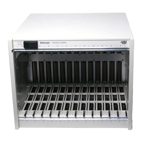
- Page 22 Getting Started This chapter provides an overview of the VX1411A IntelliFrame Mainframe. It includes installation and configuration information on user-installed options. Product Description The VX1411A IntelliFrame Mainframe is a 13-slot, C-size, VXIbus Mainframe. It fully complies with the VXIbus Specification 1.4 requirements and is VXIplug&play compatible.
- Page 23 Getting Started Air is exhausted at the sides of the mainframe, allowing you to safely stack the mainframe with other rackmount equipment. Additional equipment placed on or positioned above the product will not restrict airflow nor will that equipment be directly affected by exhaust air.
-
Page 24: Table 1-1: Vx1411A Intelliframe Mainframe Options And Upgrade Kits
Options and Upgrade Kits Table 1–1 lists the VX1411A IntelliFrame Mainframe options and upgrade kits that you can purchase and install separately. Contact your local Tektronix representative for information on the upgrade kits. The VX1411A can be upgraded to include the features of other Tektronix IntelliFrameRMainframes. -
Page 25: Table 1-2: Power Cord Identification
Getting Started Standard Accessories The VX1411A IntelliFrame Mainframe comes with the following standard accessories: H VX1411A IntelliFrame Mainframe Instruction Manual H One power cord (voltage range and plug type varies according to country, see Table 1–2) H Fuse holder H Line fuse, 15 A, 250 V H Line fuse, 20 A, 250 V H Line fuse, 6.3 A, 250 V Table 1–2: Power cord identification... -
Page 26: Table 1-3: Line Fuse Application
Getting Started Table 1–2: Power cord identification (Cont.) Plug configuration Normal usage Option number North America 230 V Switzerland 230 V Optional Accessories The VX1411A IntelliFrame Mainframe has the following optional accessories: Refer to Replaceable Parts on page 5–8 for part numbers. H Single-wide front panel fillers H Double-wide front panel fillers H Single-wide EMI front panel fillers... - Page 27 Getting Started Installation This section describes the procedures to install your mainframe. It includes procedures for installing the mainframe with the rackmount or cable tray options. This section does not include specific procedures for installing modules in the mainframe. Refer to your module documentation for information regarding the module installation instructions.
-
Page 28: Figure 1-1: Install Option 1U Cable Tray
Getting Started Remove feet (4) Opt 1U without rails 1.75–inch depth Install feet. (optional) Install 4 screws and leave 1/8 inch clearance from the chassis. Slide the cable tray over the screws; then tighten screws to secure cable tray. Figure 1–1: Install Option 1U cable tray 1–7 VX1411A IntelliFrame Mainframe Instruction Manual Artisan Technology Group - Quality Instrumentation ... -
Page 29: Figure 1-2: Install Option 1U Cable Tray
Getting Started Opt 1U with Rails 2.5–inch depth Install feet. (optional) Install butch plate. (optional) Install 4 screws, and leave 1/8 inch clearance from the Install 4 screws, and leave 1/8 inch rails. Slide the cable tray over clearance from the chassis. Slide the screws;... -
Page 30: Figure 1-3: Install Option 2U Cable Tray
Getting Started Remove feet (4) Opt 2U without rails 3.5–inch depth Install feet. (optional) Install butch plate. (optional) Install 4 screws and leave 1/8 inch clearance from the chassis. Slide the cable tray over the screws; then tighten screws to secure cable tray. Figure 1–3: Install Option 2U cable tray 1–9 VX1411A IntelliFrame Mainframe Instruction Manual... -
Page 31: Figure 1-4: Install Option 2U Cable Tray
Getting Started Opt 2U with Rails 4.25–inch depth Install feet. (optional) Install butch plate. (optional) Install 4 screws, and leave 1/8 inch clearance from the Install 4 screws, and leave 1/8 inch rails. Slide the cable tray over clearance from the chassis. Slide the screws;... - Page 32 Getting Started Front Panel SYSReset The IntelliFrameR mainframe provides you the ability to generate a backplane Activation SYSReset signal from the front panel. This feature allows you to reset the complete VXI system without having to power down the mainframe. A SYSReset activation is accomplished by pushing the right side (nonlighted side) of the On/Standby power switch.
-
Page 33: Figure 1-5: Installing The Rackmount Kit Hardware
Getting Started NOTE. To comply with VXIplug&play mounting specifications, position the rackmount adapter at the mounting holes with the adjacent identifier keys (see Figure 1–5). This results in 3.960 in (10.06 cm) from the module panel mounting surface to the rack frame mounting surface. VXIplug&play position key for VX1410A/11A/20A... -
Page 34: Figure 1-6: Assembling The Slide-Out Track Assemblies
Getting Started Install the Mainframe Use the following procedure to install the VX1411A IntelliFrame Mainframe in in the Rack the rack: 1. Identify the right and left slide-out track assemblies: find the date code label on each assembly. The assembly to be mounted in the left side of the rack (the side nearest the left side of the mainframe when it is mounted in the rack) has a date code that ends with LH (for left hand). -
Page 35: Figure 1-7: Vertical Clearance For Rack Installation (Standard Mainframe)
Getting Started 6. Select the mounting position in the rack: select two 0.5-inch spaced holes in the front rail and verify that the 1.5-inch and 14.00-inch clearances exist relative to the mounting holes as shown in Figure 1–7. NOTE. The 14-inch vertical clearance is only valid for the mainframe without the rubber feet and cable trays. -
Page 36: Figure 1-8: Installing The Slide-Out Track Assemblies In
Getting Started To mount with front and rear flanges inside of the rails, use mounting method B shown in Figure 1–8 when doing step 8. This mounting method assumes untapped holes. 8. Using the mounting method determined from the previous step, secure the right slide-out track assembly to the front and rear rails. -
Page 37: Figure 1-9: R1 Or R2 Rackmounting Screw
Getting Started 12. Lift the mainframe and insert the left and right tracks that extend from the rear of the mainframe into the ends of the tracks that you just extended. Make sure that the tracks mounted on the mainframe slip just inside the inner tracks that you extended earlier. -
Page 38: Figure 1-10: Installing The Rackmount Door (Option 2R)
Getting Started Install the Option 2R Refer to Figure 1–10 and perform the following steps to install the rackmount Rackmount Door door for Option 2R: 1. Install the bottom halves of the two hinges to the left rackmount bracket as shown in Figure 1–10. - Page 39 Getting Started Configuration After installing the mainframe, you are ready to configure it for your applica- tions. If you have not already done so, install your VXIbus modules in the mainframe following the installation guidelines for your VXIbus module. Module Selection and The VX1411A IntelliFrame Mainframe is UL listed to UL 3111-1 and CAN/ Design Guidelines CSA C22.2 No.
-
Page 40: Figure 1-11: Installing The Empty Slot Panel Fillers
Install either the optional single-wide or double-wide fillers. CAUTION. To avoid damage caused by heat use only Tektronix front panels; otherwise the shutters may activate, effectively robbing airflow from installed modules. Installing the fillers provides improved cooling for installed modules and improved EMI shielding. -
Page 41: Figure 1-12: Locations Of Safety And Chassis Ground
Getting Started Safety and Chassis The left rear of the VX1411A IntelliFrame Mainframe has a connection point for Grounds the chassis ground (see Figure 1–12). WARNING. To avoid personal injury the safety ground screw must always be in place to ensure the proper bonding of the power supply to the mainframe. You can use the chassis ground connection to connect the grounds of one or more instruments to the mainframe. -
Page 42: Figure 1-13: Installing The Emi Intermodule Shield And
Getting Started EMI Configurations Perform the following steps if you intend to install the optional EMI Intermodule shields and/or EMI filler panels. (Part numbers are listed under Optional Accessories on page 5–8): NOTE. It is only necessary to install the EMI intermodule shields if your VXIbus module does not have EMI shielding. -
Page 43: Table 1-4: Power Supply Voltages P1 And P2 Of The
Getting Started Functional Check and Performance Verification Use the information in this section to determine that the VX1411A IntelliFrame Mainframe operates properly. The functional check and performance verification consist of checking the power supply voltages. To check these voltages you will need an extender card and a digital voltmeter. - Page 44 Operating Basics Artisan Technology Group - Quality Instrumentation ... Guaranteed | (888) 88-SOURCE | www.artisantg.com...
- Page 45 Artisan Technology Group - Quality Instrumentation ... Guaranteed | (888) 88-SOURCE | www.artisantg.com...
-
Page 46: Figure 2-1: Front View Of The Vx1411A
Operating Basics This chapter provides a brief overview of the VX1411A IntelliFrame Mainframe including illustrations and descriptions of switches, indicators, and connectors. Figure 2–1 shows the front view of the VX1411A IntelliFrame Mainframe. All of the mainframe slots are labeled on the top and bottom of the mainframe. Slot 0 is reserved for the mainframe controller;... -
Page 47: Figure 2-2: Rear View Of The Vx1411A
Operating Basics The On/Standby switch on the top-left corner of the front panel applies DC voltages to the mainframe. The switch is a momentary contact switch. The switch is lighted when DC voltages are applied to the mainframe. This switch can also generate a SysReset on the VXI Backplane, refer to Appendix B: Special Configuration for configuration information. - Page 48 Operating Basics Fan Speed Control The Fan Speed switch controls the speed of the system cooling fans. When the switch is set to the variable position, the fans are set to a variable speed to reduce fan noise. The fans are automatically adjusted by the mainframe to minimize fan noise and provide appropriate cooling.
- Page 49 Operating Basics 2–4 VX1411A IntelliFrame Mainframe Instruction Manual Artisan Technology Group - Quality Instrumentation ... Guaranteed | (888) 88-SOURCE | www.artisantg.com...
- Page 50 Specifications Artisan Technology Group - Quality Instrumentation ... Guaranteed | (888) 88-SOURCE | www.artisantg.com...
- Page 51 Artisan Technology Group - Quality Instrumentation ... Guaranteed | (888) 88-SOURCE | www.artisantg.com...
-
Page 52: Table 3-1: Ac Power Source
Specifications This chapter contains the complete specifications for the VX1411A IntelliFrame Mainframe. Within each section, the specifications are arranged in functional groups such as: AC Power Source, Secondary Power, Cooling, Safety, Environ- mental, Backplane, and Mechanical. All specifications are warranted unless they are designated typical. DC Voltage Regulation is a warranted characteristic and can be directly checked by proce- dures contained in the Functional Check &... -
Page 53: Table 3-2: Secondary Power
Specifications Table 3–2: Secondary power Characteristic Description Maximum Power Available >110v Low Line Derating for V <110v 110v 0 50 55 Ambient Temperature ( C) Voltage (steady-state current) DC Current Capacity (I +24 V +12 V +5 V 80 A –2 V –15 A –5.2 V... - Page 54 Specifications Table 3–2: Secondary power (Cont.) Characteristic Description n DC Voltage Regulation Tolerance, nV Tolerance, nV Voltage +24 V +1.2 V, –720 mV +1.2 V, –720 mV +12 V +600 mV, –360 mV +600 mV, –360 mV +5 V +250 mV, –125 mV +250 mV, –125 mV –2 V –100 mV, +100 mV –100 mV, +100 mV –5.2 V...
-
Page 55: Figure 3-1: Mainframe Cooling Curve
Specifications Table 3–3: Cooling Characteristic Description Cooling System Forced air circulation (positive pressurization) with one removable filter. Two internal DC fans provide cooling for the power supply and the 13 VXIbus module slots. Fan Speed Control Rear panel switch chooses between full speed and variable speed. -
Page 56: Table 3-4: Certifications And Compliances
Specifications Table 3–4: Certifications and compliances Characteristic Description EC Declaration of Conformity Meets intent of Directive 89/336/EEC for Electromagnetic Compatibility and Low Voltage Directive 73/23/ECC for Product Safety. Compliance was demonstrated to the following specifications as listed in the Official Journal of the European Communities: EMC Directive 89/336/EEC: EN 55011... - Page 57 Specifications Table 3–4: Certifications and compliances (Cont.) Characteristic Description Immunity, AC Power Line No loss of stored data, change to control settings, degradation Transients of performance, or temporary loss of function will occur when the mainframe is subjected to the transients as described below (IEC 801-5).
-
Page 58: Table 3-5: Environmental
Table 3–5: Environmental Characteristic Description Classification The VX1411A IntelliFrame Mainframe is suitable for operation in the Tektronix and MIL-T-28800E (Type III, Class 5, Style E or F) environments as specified in this table. Atmospherics Temperature Meets the limits stated in MIL-T-28800E for Type III, Class 5... -
Page 59: Table 3-6: Backplane
Module Size 13 C-size VXI slots. The mainframe also accepts A-size or B-size modules using the 73A-851 module. Finish Tektronix TV gray paint on an aluminum chassis 3–8 VX1411A IntelliFrame Mainframe Instruction Manual Artisan Technology Group - Quality Instrumentation ... Guaranteed | (888) 88-SOURCE | www.artisantg.com... -
Page 60: Figure 3-2: Front View And Side View Of Vx1411A
Specifications 16.7 in 24.00 in (42.55 cm) (60.69 cm) 13.65 in (35.00 cm) 13.25 in (33.6 cm) Figure 3–2: Front view and side view of VX1411A IntelliFrame Mainframe 26.4 in 67.06 cm Min 18.9 in (31.4 in 79.76 cm Max) (48.0 cm) 15.00 in (38.0 cm) -
Page 61: Figure 3-4: Front View And Side View Of Intelliframe Mainframe
Specifications 26.4 in 67.06 cm Min 18.9 in (31.4 in 79.76 cm Max) (48.01 cm) 16.75 in (42.5 cm) 17.50 in (44.5 cm) 19.25 in (48.9 cm) Figure 3–4: Front view and side view of IntelliFrame Mainframe with Option 2U and Rackmount Option Table 3–8: VXI and Plug &... - Page 62 WARNING The following servicing instructions are for use only by qualified personnel. To avoid injury, do not perform any servicing other than that stated in the operating instructions unless you are qualified to do so. Refer to all Safety Summaries before performing any service.
- Page 63 Artisan Technology Group - Quality Instrumentation ... Guaranteed | (888) 88-SOURCE | www.artisantg.com...
- Page 64 Maintenance Artisan Technology Group - Quality Instrumentation ... Guaranteed | (888) 88-SOURCE | www.artisantg.com...
- Page 65 Artisan Technology Group - Quality Instrumentation ... Guaranteed | (888) 88-SOURCE | www.artisantg.com...
- Page 66 Maintenance This chapter provides procedures for inspecting and cleaning the VX1411A IntelliFrame Mainframe, removing and replacing internal mainframe compo- nents, and isolating problems to module levels. Service Strategy The service procedures in this manual provide removal and replacement procedures to repair the VX1411A IntelliFrame Mainframe to a module level. Instrument level repairs are accomplished by exchanging faulty modules with known-good modules or parts.
- Page 67 Inspect the mainframe for physical damage incurred during transit. Retain the mainframe packaging in case shipment for repair is necessary. If there is damage or deficiency, contact your local Tektronix representative. Cleaning procedures consist of exterior and interior cleaning of the mainframe and cleaning the fan filter.
-
Page 68: Figure 4-1: Removing The Fan Filter
Maintenance CAUTION. To avoid damaging the instrument, avoid getting moisture inside the mainframe during exterior cleaning; use just enough moisture to dampen the cloth or swab. Do not wash the front-panel On/Standby switch. Cover the switch while washing the mainframe. Use only deionized water when cleaning. - Page 69 Maintenance Removal and Replacement The following procedures describe how to remove and replace module-level components of the VX1411A IntelliFrame Mainframe. Refer to the exploded view illustrations in Replaceable Parts for an overview of the assembly and disassembly of the mainframe. WARNING.
-
Page 70: Figure 4-2: Removing The Mainframe Cover
Maintenance Remove screws (12) Step 1 Step 2 Step 3 Figure 4–2: Removing the mainframe cover Procedure 2: Removing To remove the VX1411A fan assembly refer to Figures 4–3, 4–4 and 4–5 while the Fan Assembly performing the following steps: 1. -
Page 71: Figure 4-3: Location Of Fan Assembly Screws On The Rear
Maintenance 7. Remove the two hex socket screws that secures the filter cover to the fan assembly using a 3/32 inch Allen wrench. Then remove the filter cover from the assembly. 8. To remove the two fans, remove the three 6-32 screws (with a pozidriv tip) that secures each fan to the inside of the fan assembly as shown in Figure 4–5. -
Page 72: Figure 4-4: Removing The Fan Assembly
Maintenance Power supply Cable cover Fan cables Fan assembly Figure 4–4: Removing the fan assembly Fans Cable tie Remove screws (6) Remove screws (2) Filter cover Figure 4–5: Removing the fans 4–7 VX1411A IntelliFrame Mainframe Instruction Manual Artisan Technology Group - Quality Instrumentation ... Guaranteed | (888) 88-SOURCE | www.artisantg.com... - Page 73 Maintenance Procedure 3: Removing To remove the fan control module, perform the following procedure (refer to the Fan Control Module Figure 4–6): 1. Loosen the captive screw that secures the cable cover to the back panel, and then remove the cable cover. 2.
- Page 74 Maintenance Procedure 4: Removing To remove the power supply from the mainframe, refer to Figure 4–4 and the Power Supply perform steps 1 through 6 of Procedure 2 on page 4–5 to remove the fan assembly. Then continue with the following steps: 1.
- Page 75 Maintenance NOTE. The bottom card guides (IntelliGuides) are replaced as a unit. The IntelliGuides are not intended to be disassembled. To replace a card guide, slide the card guide towards the rear of the mainframe and allow the front of the card guide to snap into place. 4–10 VX1411A IntelliFrame Mainframe Instruction Manual Artisan Technology Group - Quality Instrumentation ...
- Page 76 Maintenance Installing card guides Slide the card guides toward the rear of the mainframe; allow the front of the card guide to snap into place. Front Rear Removing card guides Gently pull the card guide forward until it pops out of place. Figure 4–8: Removing the top and bottom card guides 4–11 VX1411A IntelliFrame Mainframe Instruction Manual...
- Page 77 Maintenance Procedure 6: Replacing The nut rails at the top and the bottom of the front of the VX1411A IntelliFrame the Top and Bottom Nut Mainframe allow the user to securely install the modules in the mainframe by screwing the top and bottom of the modules to the front of the mainframe. Refer Rails to Figure 4–9 to remove these nut rails and perform Procedure 1 on page 4–4 to remove the mainframe cover.
- Page 78 Maintenance Procedure 7: Remove the Perform the following steps to remove the EMI DIN shields (part numbers are EMI DIN Shields listed under Replaceable Parts on page 5–9): 1. Remove any modules surrounding the slots where you intend to remove the Backplane EMI DIN shields.
- Page 79 Maintenance Procedure 8: Remove the To remove the backplane, perform Procedures 1, 2, 3, and 4 beginning on page Backplane 4–4. Refer to Figure 4–11, and then complete the following steps: 1. Remove the top cover of the mainframe (see Figure 4–9 on page 4–12, if necessary).
- Page 80 Maintenance Power switch connector Connector 6-32 Screws (17) Figure 4–11: Removing the backplane 4–15 VX1411A IntelliFrame Mainframe Instruction Manual Artisan Technology Group - Quality Instrumentation ... Guaranteed | (888) 88-SOURCE | www.artisantg.com...
-
Page 81: Table 4-1: Fuses
No component-level procedures are provided. Equipment List The following test equipment is recommended for troubleshooting procedures: H Digital Voltmeter (Tektronix DM250 series digital voltmeter) H Oscilloscope, 20 MHz BW, with 10x Probe (Tektronix TDS500A series oscilloscope) H Extender card (Tektronix 73A-850 VXIbus Extender Board Diagnostic Information The VX1411A IntelliFrame Mainframe does not include diagnostics. - Page 82 IntelliGuides (shutters). Repackaging Instructions If you need to send the VX1411A IntelliFrame Mainframe to a Tektronix field center for repair, attach a tag to the mainframe with the owner name and address, the serial number, and a brief description of the problem(s) encountered or the service required.
- Page 83 Maintenance Theory of Operation This section provides a brief overview of the theory of operation for the VX1411A IntelliFrame Mainframe. Figure 4–12 shows the functional block diagram of the mainframe and the major components. The VX1411A IntelliFrame Mainframe contains the following major compo- nents: H Power supply H Backplane...
- Page 84 Maintenance +5 V Standby Fan speed switch Fan 2 AC in Fan 1 Power supply P26 P27 P28 Backplane board 10P1 11P1 12P1 11P2 10P2 12P2 Slot 0 Slot 1 Slot 2 Slot 3 Slot 4 Slot 5 Slot 6 Slot 7 Slot 8 Slot 9...
- Page 85 Maintenance 4–20 VX1411A IntelliFrame Mainframe Instruction Manual Artisan Technology Group - Quality Instrumentation ... Guaranteed | (888) 88-SOURCE | www.artisantg.com...
- Page 86 Replaceable Parts Artisan Technology Group - Quality Instrumentation ... Guaranteed | (888) 88-SOURCE | www.artisantg.com...
- Page 87 Artisan Technology Group - Quality Instrumentation ... Guaranteed | (888) 88-SOURCE | www.artisantg.com...
- Page 88 670-7918-03 670-7918-XX When you order parts, Tektronix will provide you with the most current part for your product type, serial number, and modification (if applicable). At the time of your order, Tektronix will determine the part number revision level needed for your product, based on the information you provide.
-
Page 89: Table 5-1: Vx1411A Intelliframe Mainframe Common Replaceable Parts
Module Servicing Modules can be serviced by selecting one of the following two options. Contact your local Tektronix service center or representative for repair assistance. Module Repair and Return. You may ship your module to us for repair, after which we will return it to you. - Page 90 Items in this section are referenced by figure and index numbers to the exploded view illustrations that follow. Tektronix Part Number Use this part number when ordering replacement parts from Tektronix. 3 and 4 Serial Number Column three indicates the serial number at which the part was first effective. Column four indicates the serial number at which the part was discontinued.
- Page 91 71400 BUSSMANN 114 OLD STATE RD ST LOUIS MO 63178 DIV OF COOPER INDUSTRIES INC PO BOX 14460 80009 TEKTRONIX INC 14150 SW KARL BRAUN DR BEAVERTON OR 97077–0001 PO BOX 500 86928 SEASTROM MFG CO INC 456 SEASTROM STREET TWIN FALLS, ID 83301 5–4...
- Page 92 Replaceable Parts 5–5 VX1411A IntelliFrame Mainframe Instruction Manual Artisan Technology Group - Quality Instrumentation ... Guaranteed | (888) 88-SOURCE | www.artisantg.com...
- Page 93 Replaceable Parts Replaceable parts list Fig. & Tektronix part Serial no. Serial no. Mfr. index number effective discont’d Name & description code Mfr. part number number 5–1 CABINET AND CHASSIS ASSEMBLY –1 212–0193–00 SCREW,EXT RLV:8–32 X 0.375 BUTTON HEAD,HEX 0KB01...
- Page 94 Replaceable Parts Figure 5–1: Cabinet and chassis assembly 5–7 VX1411A IntelliFrame Mainframe Instruction Manual Artisan Technology Group - Quality Instrumentation ... Guaranteed | (888) 88-SOURCE | www.artisantg.com...
- Page 95 Replaceable Parts Replaceable parts list Fig. & Tektronix part Serial no. Serial no. Mfr. index number effective discont’d Name & description code Mfr. part number number 5–2 CHASSIS PARTS AND BACKPLANE –1 260–2682–00 SWITCH,PUSH:SPST,GOLD OVER NICKEL CONTACT,0.4V @ 80009 260–2682–00 28V,ILLUMINATED BUTTON, PANEL MNT W/CABLE –2...
- Page 96 Replaceable Parts Figure 5–2: Circuit boards and chassis parts 5–9 VX1411A IntelliFrame Mainframe Instruction Manual Artisan Technology Group - Quality Instrumentation ... Guaranteed | (888) 88-SOURCE | www.artisantg.com...
-
Page 97: Description
Replaceable Parts Replaceable parts list Fig. & Tektronix part Serial no. Serial no. Mfr. index number effective discont’d Name & description code Mfr. part number number 5–3 POWER SUPPLY AND FAN ASSEMBLY –1 333–4238–00 PANEL,REAR:MONITOR,W/LEXAN OVERLAY,VX1411A 80009 333–4238–00 –2 174–3694–00 CABLE ASSY SP:DESCRETE,FAN,CPD,8.0L,1X6,0.1CT,... - Page 98 Replaceable Parts Figure 5–3: Power supply and fan assembly 5–11 VX1411A IntelliFrame Mainframe Instruction Manual Artisan Technology Group - Quality Instrumentation ... Guaranteed | (888) 88-SOURCE | www.artisantg.com...
- Page 99 Replaceable Parts Replaceable parts list Fig. & Tektronix part Serial no. Serial no. Mfr. index number effective discont’d Name & description code Mfr. part number number 5–4 1R RACKMOUNT ASSEMBLY –0 020–2221–XX COMPONENT KIT:RACKMOUNT KIT 1R 80009 0202221XX (KIT CONTAINS ITEMS 1 THRU 8) –1...
- Page 100 Replaceable Parts Figure 5–4: 1R Rackmount assembly 5–13 VX1411A IntelliFrame Mainframe Instruction Manual Artisan Technology Group - Quality Instrumentation ... Guaranteed | (888) 88-SOURCE | www.artisantg.com...
- Page 101 Replaceable Parts Replaceable parts list Fig. & Tektronix part Serial no. Serial no. Mfr. index number effective discont’d Name & description code Mfr. part number number 5–5 2R RACKMOUNT AND DOOR ASSEMBLY –0 020–2222-XX COMPONENT KIT:RACKMOUNT KIT 2R 80009 0202222XX (KIT CONTAINS ITEMS 1 THRU 12) –1...
- Page 102 Replaceable Parts Figure 5–5: 2R Rackmount and door assembly 5–15 VX1411A IntelliFrame Mainframe Instruction Manual Artisan Technology Group - Quality Instrumentation ... Guaranteed | (888) 88-SOURCE | www.artisantg.com...
- Page 103 Replaceable Parts Replaceable parts list Fig. & Tektronix part Serial no. Serial no. Mfr. index number effective discont’d Name & description code Mfr. part number number 5–6 OPTION 1U CABLE TRAY –0 020–2223–XX COMPONENT KIT:CABLE TRAY 1U KIT 80009 0202223XX (KIT INCLUDES ITEMS 1 THRU 3) –1...
- Page 104 Replaceable Parts Figure 5–6: Option 1U cable tray 5–17 VX1411A IntelliFrame Mainframe Instruction Manual Artisan Technology Group - Quality Instrumentation ... Guaranteed | (888) 88-SOURCE | www.artisantg.com...
- Page 105 Replaceable Parts Replaceable parts list Fig. & Tektronix part Serial no. Serial no. Mfr. index number effective discont’d Name & description code Mfr. part number number 5–7 OPTION 2U CABLE TRAY –0 020–2224–XX COMPONENT KIT: CAB;E TRAY 2U KIT 80009...
- Page 106 Replaceable Parts Figure 5–7: Option 2U cable tray 5–19 VX1411A IntelliFrame Mainframe Instruction Manual Artisan Technology Group - Quality Instrumentation ... Guaranteed | (888) 88-SOURCE | www.artisantg.com...
- Page 107 Replaceable Parts 5–20 VX1411A IntelliFrame Mainframe Instruction Manual Artisan Technology Group - Quality Instrumentation ... Guaranteed | (888) 88-SOURCE | www.artisantg.com...
- Page 108 Appendices Artisan Technology Group - Quality Instrumentation ... Guaranteed | (888) 88-SOURCE | www.artisantg.com...
- Page 109 Artisan Technology Group - Quality Instrumentation ... Guaranteed | (888) 88-SOURCE | www.artisantg.com...
- Page 110 Appendix A: Power Budget Worksheet Use the Power Budget Worksheet to determine the operating parameters of the VX1411A IntelliFrame Mainframe and any installed modules. Enter the steady-state current (I ) and the dynamic current (I ) for each module. Add the individual currents to determine the total current needed for each power rail.
- Page 111 Power Requirements +12V –12V +24V –24V –5.2V –2V Module Slot Total Current of All Modules VX1411A Current Limit Individual Current Sums Less Than VX1411A Current Limits? Power Calculation (V x total Total Power < 700W Artisan Technology Group - Quality Instrumentation ... Guaranteed | (888) 88-SOURCE | www.artisantg.com...
- Page 112 Appendix B: Special Configuration This appendix contains information for configuring your IntelliFrameR Mainframe for specific situations not documented earlier in this manual. This special configuration requires you to disassemble parts of the mainframe to access cables and circuit boards. Refer to the Maintenance chapter for detailed information on the assembly and disassembly procedures.
- Page 113 Appendix B: Special Configuration Cut tie warp SYSReset connector Figure B–1: SYSReset cable connector B–2 VX1411A IntelliFrame Mainframe Instruction Manual Artisan Technology Group - Quality Instrumentation ... Guaranteed | (888) 88-SOURCE | www.artisantg.com...
- Page 114 Glossary Artisan Technology Group - Quality Instrumentation ... Guaranteed | (888) 88-SOURCE | www.artisantg.com...
- Page 115 Artisan Technology Group - Quality Instrumentation ... Guaranteed | (888) 88-SOURCE | www.artisantg.com...
- Page 116 Glossary The terms in this glossary are defined as used in the VXIbus System. Although some of these terms may have different meanings in other systems, it is important to use these definitions in VXIbus applications. Terms which apply only to a particular instrument module are noted. Not all terms appear in every manual.
- Page 117 Glossary Client In shared memory protocol (SMP), that half of an SMP channel that does not control the shared memory buffers. CLK10 A 10 MHz, 100 ppm, individually buffered (to each module slot), differential ECL system clock that is sourced from Slot 0 and distributed to Slots 1–12 on P2.
- Page 118 Glossary Custom Device A special-purpose VXIbus device that has configuration registers so as to be identified by the system and to allow for definition of future device types to support further levels of compatibility. Data Transfer Bus One of four buses on the VMEbus backplane. The Data Transfer Bus allows Bus Masters to direct the transfer of binary data between Masters and Slaves.
- Page 119 IntelliFrameR mainframe A family of VXI mainframes from Tektronix that automatically direct airflow to the installed modules, have an autoconfigure backplane, have adjustable rack kits and cable trays (optional), and can be upgraded.
- Page 120 A device that monitors backplane power and reports fault conditions. The top-most backplane connector for a given module slot in a vertical mainframe such as the Tektronix VX1411A IntelliFrame Mainframe. The left-most backplane connector for a given slot in a horizontal mainframe.
- Page 121 Glossary READY Indicator A green LED indicator that lights when the power-on diagnostic routines have been completed successfully. An internal failure or failure of +5 V power will extinguish this indicator. Register Based Device A VXIbus device that supports VXI register maps, but not high level VXIbus communication protocols;...
- Page 122 Glossary See Shared Memory Protocol. STARX Two (2) bi-directional, 50 W, differential ECL lines that provide for inter-module asynchronous communication. These pairs of timed and matched delay lines connect slot 0 and each of slots 1 through 12 in a mainframe.
- Page 123 Glossary Test System A collection of hardware and software modules that operate in concert to test a target DUT. TTLTRG Open collector TTL lines used for inter-module timing and communication. VXIbus Subsystem One mainframe with modules installed. The installed modules include one module that performs slot 0 functions and a given complement of instrument modules.
- Page 124 Index Artisan Technology Group - Quality Instrumentation ... Guaranteed | (888) 88-SOURCE | www.artisantg.com...
- Page 125 Artisan Technology Group - Quality Instrumentation ... Guaranteed | (888) 88-SOURCE | www.artisantg.com...
- Page 126 Index fan filter cleaning, 4–3 fan speed switch, 2–3 accessories fans, removing, 4–5 optional, 1–5 fault isolation procedures, 4–16–4–20 standard, 1–4 cooling, 4–17–4–18 power supply, 4–17 functional check procedure, 1–22 fuses, line, 4–16 backplane, 1–2, 4–14–4–16, 4–18 removing, 4–14–4–16 specifications, 3–8 ground chassis, 1–20 safety, 1–20...
- Page 127 Index Performance verification, 1–22 environmental, 3–7 plug & play compliances, 3–10 mechanical, 3–8 power connector, 2–2 secondary power, 3–2 power cord, selecting, 1–5 standard monitor board, removing, 4–8 power supply, 1–1, 4–9, 4–18 static precautions, 4–1 fault isolation, 4–17 switches removing, 4–9 fan speed, 2–3 On/Standby, B–1...
- Page 128 Artisan Technology Group - Quality Instrumentation ... Guaranteed | (888) 88-SOURCE | www.artisantg.com...
- Page 129 Artisan Technology Group - Quality Instrumentation ... Guaranteed | (888) 88-SOURCE | www.artisantg.com...
Need help?
Do you have a question about the IntelliFrame VX14 A Series and is the answer not in the manual?
Questions and answers