Table of Contents
Advertisement
Quick Links
DT-366 LED Stroboscope
Operation Manual
Use in flammable environments is prohibited. Use in this manner may
result in fire or explosive.
Do not look directly into the LED light Source. This may result in eye
injury.
Do not use or store in the following environments: Direct sunshine con-
densation, dust or caustic.
Do not alter, or modify of improperly. Such action may cause damage
and void warranty.
Operate with 0-35°C (32-95°F), 35-85% RH. Use outside of this range
may alter operation of the unit.
Case may become excessively hot when used continuously for more
than 2 hours. Mount unit on a tripod or other fixed device.
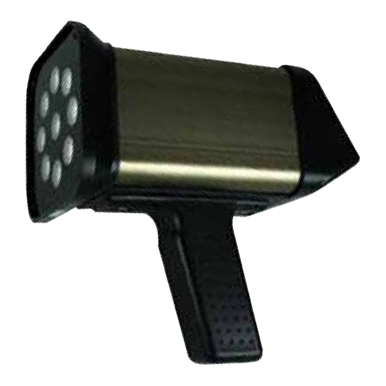
The DT-366 is a portable, battery-powered strobo-
scope
that utilizes super bright CREE High-Powered LED lamps.
The DT-366's LED array provides a bright, stable strobe light over
a wide measurement range with a lifetime far exceeding xenon-lit
stroboscopes. Combined with large, backlit LCD display, oper-
ation is simple with the 8 button keypad and quick rate-adjust-
ment dial. Phase shift, flash duration, plus flash rate all are easily
viewed and adjustable. The unit can function by user altered flash
frequency or from a remote sensor's signal input which will auto-
matically adjust the stroboscope to the corresponding process
fluctuations. Containing a rechargeable lithium battery, a single
charge is able to last up to a full 12 hours of operation.
The DT-366 is designed for speed and frequency measurements
in motion and vibration analysis applications. It is ideal for pre-
dictive and preventive maintenance applications such as: motors,
shafts, roto-gravure printing, extruders, blow molding, wire letter-
ing and striping, engraving, pulse jets, water jets, fans, cams, gear
teeth, belt inspections, fuel injectors, vibration analysis, spindle
spinning, cutting blade timing and sharpness, plus many more in
the printing, packaging, textile, automotive, cable, mining, steel,
chemical, optical, medical and shipbuilding industries.
Operation Panel Located on Control Enclosure
POWER: Power on and off.
MODE: Select mode of operation or Parameter Menu: Internal/
External/Parameter Settings
SET: Change Units (FPM to Hz); In Parameter Menu scroll through
Parameter Settings, Store setting values.
x2: Multiplies the flash rate/frequency by a factor of 2.
1/2: Divides the flash rate/frequency by a factor of 2.
RATIO: Adjusts flash duration (flash pulse width) in Internal/Ex-
ternal modes.
"+": Advance image forward 3 degrees at a time in internal mode.
In parameter setting mode, adjusts setting values.
"-": Retard image backwards 3 degrees at a time in internal mode.
In parameter setting mode, adjusts setting values.
Dial: Set flash rate or frequency. CW: Increase flash rate/frequen-
cy. CCW: Decrease flash rate/frequency. (Turn dial quickly to
drastically change value; Turn dial slowly to change value by 1
digit.) In parameter setting mode, CW or CCW rotation chang-
es the setting value. *Dial located on side of unit.
SEALS USA, Inc.
Instruments Division
sales@GlobalTestSupply.com
SPECIFICATIONS
Flash Rate Range: 30 to 120,000 FPM ; 1-2000 Hz
Accuracy: 0.01%±1 digit of F.S. @ 77° F (25°C)
Lux Rating (Approx.): 6000 FPM: Distance 8˝ (20 cm) 6850 lx
with 10˝ (254 mm) irradiation dia., Distance 20˝ (50 cm) 2325 lx
with 14˝ (355 mm) irradiation dia. 1500 FPM: Distance 8˝ (20 cm)
3395 lx with 10˝ (254 mm) irradiation dia., Distance 20˝ (50 cm)
1350 lx with 14˝ (355 mm) irradiation dia
Lamp Lifetime: Approximately 3~5 years depending on usage.
Display: Backlit LCD
Resolution: 60 ~12,000 FPM = 0.1 FPM; 12,001~120,000 FPM
= 1 FPM; 1~200 HZ = 0.01 Hz; 201~2000 = 0.1 Hz
Flash Duration: 0.1°- 2.5°
Power Requirement: 100-240 VAC 50/60Hz
Battery: Lithium DC 16.8V 2600 mAh
Battery Life: Approx. 12 hrs depending on settings
External Sensor Input: 15 V Pulse Input; Mini-USB
Sensor Power Supply: 15 V dc up to 50 mAh
Input Pulse Width: Over 50 µs
Input Signal Flash Delay: 0-999 ms; 0-359°
Temperature Limits: 32-95°F (0-35°C)
Humidity Limits: 35 to 85% RH
Enclosure: Aluminum & ABS
Mounting: 1/4-20 UNC Thread
Enclosure Rating: IP54
Product Weight: 2.15 lb (0.98 kg)
Package Weight: 5.85 lb (2.65 kg)
Dimensions: 8 x 4.3 x 7.6" (203 x 110 x 192 mm)
Approvals: CE
Warrenty: 1 Year
Included Accessories: Carrying Case, Power Charging Adapter
with cord bottom and top handle
Tel: (630)924-7138
-Direct.com
Email: support@seals-usa.com
1.888.610.7664
Advertisement
Table of Contents

Related Manuals for Nidec DT-366


Summary of Contents for Nidec DT-366
- Page 1 Accuracy: 0.01%±1 digit of F.S. @ 77° F (25°C) Lux Rating (Approx.): 6000 FPM: Distance 8˝ (20 cm) 6850 lx The DT-366’s LED array provides a bright, stable strobe light over with 10˝ (254 mm) irradiation dia., Distance 20˝ (50 cm) 2325 lx a wide measurement range with a lifetime far exceeding xenon-lit with 14˝...
- Page 2 LCD Display FUNCTION INSTRUCTIONS Mode Selection - To switch between INTERNAL, EXTERNAL and Main PARAMETER menu, press and release the MODE key. For details Data about Parameter setting mode, please refer to Parameter setting Display menu section. Parameter Icons Units Data Display Main Data Display •Flash rate value will be displayed in internal flashing or Exter-...
- Page 3 Phase Shift (Angle) - First, press ‘SET” key, then enter this mode. When the rotation speed of the target object and the flash rate of the DT-366 becomes equal, the phase shift func- tion can be used to delay the flash so that the image will appear to rotate incrementally.
- Page 4 Delay Time: 10 ms sor performance. The DT-366 does not flash at the 1st trigger pulse as shown below Additionally, there are several settings that can be adjusted in Ex- in the diagram, DT-366 flashes from the external trigger after 10 ternal Trigger mode, including phase shift, delay time, and flash duration.
- Page 5 Parameter Settings To enter parameter setting menu, press “MODE” until the LCD dis- delay time, the delay time is ignored and the DT-366 flashes as if plays “P”. When the display shows “P’, press the SET key to cycle the delayed time equals 0.
- Page 6 Back Light Setting Mounting The LCD display of the DT-366 stroboscope has a backlight that To mount permanently, remove the two screws holding the trigger can be turned on or off in the parameter settings. Turning off the handle. The threaded adapter will now be visible. Discard screws backlight will conserve battery power.
Need help?
Do you have a question about the DT-366 and is the answer not in the manual?
Questions and answers