Table of Contents
Advertisement
Quick Links
Advertisement
Table of Contents

Related Manuals for Nidec DT-3011J


Summary of Contents for Nidec DT-3011J
- Page 1 STROBOSCOPE Weatherproof IP65 DT-3011J INSTRUCTION MANUAL Read this manual thoroughly before use. Before use, please carefully read these safety precautions as well as instructions, and follow them for proper operation. www.nidec.com/jp/nidec-shimpo...
- Page 2 Safety Precautions Be sure to observe Be sure to read the entire instruction manual thoroughly before initial set-up, operation and maintenance. The instruction manual provides two grades of safety warnings: “Danger” and “Caution”. Each of them is an important description related to safety. Be sure to observe. This indicates the possibility of fire, severe injury, and even death if a user disregards the instruction Danger and operates the unit improperly.
-
Page 3: Table Of Contents
Contents Overview of this product ..................................3 Before use ....................................... 3 2.1 Checking the supplied items ................................3 Part names and functions ................................... 4 3.1 Main unit ....................................... 4 3.2 Operation Panel ....................................5 3.3 Display ........................................6 3.3.1 Part names and function instructions ..........................6 Functions and operations ................................... -
Page 4: Overview Of This Product
● Sealed structure to prevent water and dust from entering. Before use 2.1 Checking the supplied items Check that the four items below are supplied DT-3011J One (1) DT-3011J Main unit Accessories One (1) Power cable (9m) Instruction Manual One (1) This document... -
Page 5: Part Names And Functions
Part names and functions 3.1 Main unit Xenon Lamp Operation Panel Power Switch Power Connector... -
Page 6: Operation Panel
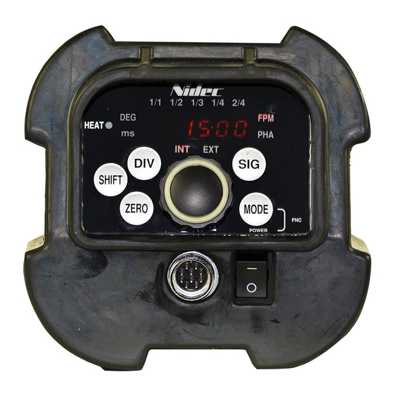
3.2 Operation Panel ⑤ ④ ⑥ ③ ② ⑦ ① Function Instructions No. Power Switch Turns the power ON/OFF ① Turn this clockwise or counterclockwise to change the emission frequency and some Dial (LAMP POWER) setting value. ② Press and hold the center of this to turn the lamp ON/OFF. Press this to switch the LED display as follows MODE Flashes Per Minute mode (FPM mode) →... -
Page 7: Display
3.3 Display 3.3.1 Part names and function instructions ④ Numerical display ③ Division display ⑤ Delay type display 1/1 1/2 1/3 1/4 2/4 ② Mode display HEAT ① Emission setting display ⑥ Heat lamp SHIFT ZERO MODE Display Instructions No. Each press of “SIG”... -
Page 8: Functions And Operations
Functions and operations 4.1 Power ON/OFF Press the power switch when the power is OFF to turn the power ON. When power is turned ON, the model is indicated, followed by internal oscillation emission or external synchronous emission. Operation Display When the power is OFF Displayed “dt”... -
Page 9: Lamp On / Off
4.1.1 LAMP ON / OFF Press and hold the center of the dial to turn ON the LAMP when emission setting is displayed on the screen. Press and hold again while flashing to turn OFF the LAMP . Operation Display Press and hold the dial to flash. -
Page 10: Emission Mode And Settings
4.2 Emission mode and settings Emission mode 詳細 Internal oscillation emission ( “INT” ) Flash at the set frequency. External synchronous emission ( “ EXT” ) Flash in synchronization with an external trigger pulse input. Function mode Configure the settings. 4.2.1 How to switch INT and EXT Each press of “SIG”... -
Page 11: Internal Oscillation Emission
4.3 Internal oscillation emission ・On “INT”, the Xenon lamp flashes at the displayed emission value. ・”INT” has the following 2 mode settings. Mode settings FPM mode PHA mode Shift the timing of flash. Set the emission count per minute The phase can be changed by a Instructions [FPM] (flashes per minute) degree or a millisecond. - Page 12 Press “MODE” to FPM mode PHA mode (DEG) switch to PHA mode (DEG)
-
Page 13: Pha Mode (Int)
4.3.2 PHA mode (INT) When the rotation (motion) cycle of a measured object matches with the strobe flash cycle, the measured object appears to stand still. Use the PHA mode in order to adjust the stop angle (position). The phase can be changed by 1° using dial within the range between 1° and 359° in the PHA mode. Press “MODE”... -
Page 14: External Synchronous Emission
4.4 External synchronous emission ・External synchronous emission is the function to emit a strobe flash in synchronization with an external trigger pulse input. ・You can set which edge of the external trigger pulse triggers emission, the rising edge or falling edge. ・A timing (delay) from the external trigger pulse input with the strobe flash emission can be optionally set using time and angle. -
Page 15: Fpm Mode Setting (Ext)
4.4.1 FPM mode setting (EXT) Operation Display Press “MODE” to switch to PHA mode (DEG) PHA mode (DEG) EXT FPM mode Press “SIG” to switch to INT FPM mode... -
Page 16: Pha Mode Setting (Ext)
4.4.2 PHA mode setting (EXT) Delay emission can be set within the input signal range between 180 and 2750[fpm]. In the PHA mode, the phase from the external trigger pulse entry to strobe flash emission can be changed by 1° using the dial within the range between 1°... -
Page 17: Divide Ratio Setting (Only For Ext)
4.5 Divide ratio setting (for EXT) 4.5.1 Divide ratio Flash as follows in accordance with the divide ratio. Input pulse MODE 1/1 MODE 1/2 MODE 1/3 MODE 1/4 MODE 2/4 4.5.2 Divide ratio setting Operation Display Each press of ”DIV” switches divide ratio. -
Page 18: Function Mode
4.6 Function mode Turn the power ON while pressing the “MODE” to enter the function mode. During the function mode, turn the dial (CW/CCW) to change the settings. And press “MODE” to save the setting and move to the next setting item. (F1⇒F2⇒F3 end) If the power is turned OFF in the middle of the function mode, the changed value will not be saved in the memory. - Page 19 In function mode 1, in which the edge of the external pulse triggers emission, the rising edge or falling edge, can be set (for EXT). Operation Display Indicates alternately *Previous setting value The default setting is “L-H” Turn the dial and it will stop indicating alternately.
- Page 20 In function mode 2, the input circuit setting can be changed. Operation Display Indicates alternately *Previous setting vale The default setting is “OFF” Turn the dial and it will stop indicating alternately. Change the setting value CW:On CCW:OFF Open collector input Voltage pulse input (Pull up the external input circuit) (Pull down the external input circuit)
- Page 21 In function mode 3, the measurement range on INT can be set. Operation Display Indicates alternately *Previous setting vale The default setting is “2500” Turn the dial and it will stop indicating alternately. Change the setting value Increase / decrease by 1 [fpm] Available setting range: 200 to 2500 [fpm] Save the changes and go to the home...
-
Page 22: Saving Function
4.7 Saving function While using the unit while on INT and EXT, turn the power OFF to save the setting value to that which it was before turning the power OFF. When the power is turned ON again, operation starts from the previous setting value. 4.7.1 Saving the setting values When the power is OFF, the setting values are saved as the following figure. -
Page 23: Initialize
4.7.2 Initialize The memory can be erased by initializing the saving function. Operation Display The power switch ON while pressing “ZERO” and “MODE” The power switch ON while pressing “ZERO” and “MODE” Press “SHIFT” and Confirm initialization Displays for a second Press “SHIFT”... -
Page 24: Initializing The Setting Values
4.7.3 Initializing the setting values The current settings will be erased and replaced as follows. (Including the function mode.) The initial setting display The initial emission setting The initial mode PHASE(DEG) PHASE(ms) PHASE(DEG) PHASE(ms) 2500 * On EXT, underlines are displayed until the external signal inputs occur. -
Page 25: External Signal I/O Connector Specifications And Pin Assignment
4.8 External signal I/O connector specifications and Pin assignment RM15WTRZB-10P (71) (Hirose Electric Group) Pin number Signal name Remarks Power supply (+) Power supply(-) External pulse input Earth Earth Pin assignment... -
Page 26: External Pulse Input
4.9 External pulse input Connect the unit to external devices (sensors, etc.) to allow the strobe to emit light using the pulse signal from the devices on external synchronous emission. Available input frequency Available measurement range 180 to 2750 fpm(3.0 to 45.8 Hz) :... -
Page 27: Lamp Replacement
4.10 Lamp replacement Lamp life is about 100 million flashes. Although rotation speed is displayed, no flash is emitted. When the flash is intermittently emitted, this indicates the lamp must be replaced. Be sure to replace the lamp with the following steps. Be sure to use the specified lamp.Please contact us or the retailer where you purchased this product if you need it. -
Page 28: Specifications
Specifications 5.1 Specifications list Emission count 200 to 2500 fpm Resolution 1 fpm Phase change function Available (PHA mode) Internal Limit function Available (adjustable in the function mode 3) oscillation Measurement range:200 to 2500 fpm emission Delayed emission function Within the range (angle):0 to 359°, available to set by1° Within the range (time) :0.0 to 299.2 ms, available to set by 0.1 ms H level:5 to 24 V L level:0 to 1 V... -
Page 29: External Dimensions
5.2 External dimensions... -
Page 30: Troubleshooting
Troubleshooting Troubleshooting Symptoms Factors Causes Solution The Xenon lamp life. Replace the lamp,If the problem Emissinon occurs inconsistently. The Xenon lamp failure. Internal circuit failure. has not been solved, ask for repair. The Xenon lamp life. Replace the lamp,If the problem Emission sometimes stops.
Need help?
Do you have a question about the DT-3011J and is the answer not in the manual?
Questions and answers