Table of Contents
Advertisement
Quick Links
Advertisement
Table of Contents

Related Manuals for Star TSP847IIU-24


Summary of Contents for Star TSP847IIU-24
- Page 1 THERMAL PRINTER TSP800II SERIES Hardware Manual...
- Page 2 Trademark acknowledgments TSP800II: Star Micronics Co., Ltd. Notice • All rights reserved. Reproduction of any part of this manual in any form whatsoever, without STAR’s express permission is forbidden. • The contents of this manual are subject to change without notice.
-
Page 3: Table Of Contents
TABLE OF CONTENTS 1. Unpacking and Installation ........................1 1-1. Unpacking ............................1 1-2. Choosing a place for the printer ....................2 2. Parts Identification and Nomenclature ....................3 3. Setup ................................4 3-1. Connecting the Cable to the PC ....................4 3-2. Connecting the Cable to the Printer .....................5 3-3. - Page 4 13. USB and Ethernet Interface ........................52 13-1. USB Interface Specifications .....................52 13-2. Ethernet Interface Specifications....................52 14. Peripheral Unit Drive Circuit ......................53 15. Memory Switch Settings ........................55 16. Release History .............................56 Please access the following URL http://www.star-m.jp/eng/dl/dl02.htm for the latest revision of the manual.
-
Page 5: Unpacking And Installation
1. Unpacking and Installation 1-1. Unpacking After unpacking the unit, check that all the necessary accessories are included in the package. Printer CD-ROM Paper roll Setup sheets Note Note: The ferrite core and fastener provided with your printer depend on your printer configuration. Fig. -
Page 6: Choosing A Place For The Printer
1-2. Choosing a place for the printer Before actually unpacking the printer, you should take a few minutes to think about where you plan to use it. Remember the following points when doing this. P Choose a firm, level surface where the printer will not be exposed to vibration. P The power outlet you plan to connect to for power should be nearby and unobstructed. -
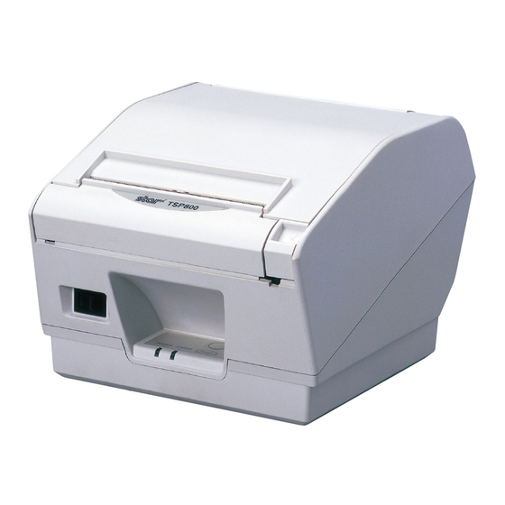
Page 7: Parts Identification And Nomenclature
2. Parts Identification and Nomenclature Printer cover Open this cover to load or replace paper. Power switch Used to turn on/ off power to the printer. Control panel Features LED indicators to Cover open lever indicate printer status and switches to operate the printer. Push this lever in the direction of the arrow to open the printer cover. -
Page 8: Setup
3. Setup 3-1. Connecting the Cable to the PC 3-1-1. Parallel Interface Cable Connect the parallel interface cable to a parallel port of your PC. 3-1-2. RS-232C Interface Cable Connect the RS-232C interface cable to a RS-232C port of your PC. 3-1-3. -
Page 9: Connecting The Cable To The Printer
3-2. Connecting the Cable to the Printer Note that the interface cable is not provided. Please use a cable that meets specifications. CAUTION Before connecting/disconnecting the interface cable, make sure that power to the printer and all the devices connected to the printer is turned off. Also make sure the power cable plug is disconnected from the AC outlet. - Page 10 3-2-2. RS-232C Interface Cable (1) Make sure the printer is turn off. CAUTION Before connecting/disconnecting the interface cable, make sure that power to the printer and all the devices connected to the printer is turned off. Also make sure the power cable plug is disconnected from the AC outlet.
- Page 11 3-2-4. Connecting Ethernet Cable If a ferrite core is included, install the ferrite core onto the Ethernet cable according to the fol- lowing procedure to prevent electrical noise. If a ferrite core is not included, perform steps (1) and (5) only. When using an Ethernet cable that is 10 m or less, shielded cable is recommended.
-
Page 12: Installing The Printer Software
3-3. Installing the Printer Software Here is the procedure for installing the printer driver and utility software, which are stored on the supplied CD-ROM. The procedure applies to the Windows operating systems shown below. • Windows XP (SP2 or later) •... -
Page 13: Connecting The Optional Ac Adapter
3-4. Connecting the Optional AC Adapter Note: Before connecting/disconnecting the AC adapter, make sure that power to the printer and all the devices connected to the printer is turned off. Also make sure the power cable plug is disconnected from the AC outlet. (1) Connect the AC adapter to the power cable. -
Page 14: Turning Power On
3-5. Turning Power On Make sure that the Power cord has been connected as described in 3-4. Turn ON the power switch located on the front of the printer. The POWER lamp on the control panel will light up. Power switch CAUTION We recommend that you unplug the printer from the power outlet whenever you do not plan to use it for long periods. -
Page 15: Connecting To A Peripheral Unit
3-6. Connecting to a Peripheral Unit You can connect a peripheral unit to the printer using a modular plug. See “Modular plug” on page 53 for details about the type of modular plug that is required. Note that this printer does not come with a modular plug or wire, so it is up to you to obtain one that suits your needs. -
Page 16: Loading The Paper Roll
3-7. Loading the Paper Roll Be sure to use paper roll that matches the printer’s specification. 1 Push the cover open lever and open the printer cover. For the RX model: Turn the key under the cover open lever so that the lock is "OPEN."... - Page 17 3-7-1. Removing the Tension Bar When using thermal paper roll, the tension bar unit may or may not be necessary, depending on the paper thickness. If the tension bar unit is unnecessary, remove it in accordance with the procedure indicated below. The tension bar unit is unnecessary when using thermal label paper roll (tack label paper).
- Page 18 3-7-2. Removing the Paper Roll Holder When using a paper roll with an 79.5 mm width, install the paper roll holder into the groover as shown. And change the setting at memory switch #4. For instructions on setting the memory switch, refer to the separate Specifications Manual.
- Page 19 Caution Symbol This symbol is placed near the thermal head to indicate that it may be hot. Never touch the thermal head immediately after the printer has been used. Let the thermal head cool for a few minutes before touching it. Never touch the thermal head with your hands because it can generate static electricity, which can damage the device in the thermal head.
- Page 20 9) A printed piece of thermal paper may become electrically charged. If the printer is placed vertically or mounted on a wall, the cut piece of paper may stick to the printer, instead of falling. Beware that this could cause a problem if you use a stacker that stores the pieces of paper that fall freely.
-
Page 21: Consumable Parts And Ac Adapter
When consumable parts have run out, use those specified in the table below. Note: Access the following URL for the information of the recommended paper. http://www.star-m.jp/eng/dl/dl02.htm Make sure that the AC adapter specified in the table is used. Use of consumable parts or AC adapter which are not specified in the table may result in dam- age to the printer, fire or electric shock. - Page 22 (2) Effective Print Width Paper Width Right / Left Margin (mm) Effective Print Width Number of Print Columns (12 × 24 Font) (mm) (mm) 115.5 ± 0.5 79.5 ± 0.5 Left Margin Effective Print Width Right Margin Paper Width – 18 –...
-
Page 23: Thermal Label Paper Roll (Tack Label Paper)
4-2. Thermal Label Paper Roll (Tack Label Paper) (1) Label paper specification Backing paper width: 110±0.5 mm Outer roll diameter: ø100 mm or less +0.3 Take up paper roll width: 112 Thickness: Max. 150 μm Core outer/inner diameter: core inner diameter ø25.4±1 mm/core outer diameter ø32±1 mm Printed surface: Outer edge of roll... - Page 24 • Detailed Diagrams of Recommended Tack Label Specifications Tack label ø32 ± 1 ø25.4 ± 1 Paper tube +1.5 -1.0 (Rolled dimension) Release paper Base material 30 ±1 – 295 ±3 (backing paper) (label paper) 5 ± 1 (Label length) Printing direction Black mark (back of diagram)
-
Page 25: Ac Adapter (Option)
• Cut Position / Printing Line / Black Mark Sensor’s Positional Relationship Effective printing range Cut position Printing line Black mark sensor • Min. Label Pitch / Cut Position / Printing Line / Black Mark Sensor’s Positional Relationship Effective printing range Cut position Printing line Black mark sensor... -
Page 26: Control Panel And Other Functions
5. Control Panel and Other Functions 5-1. Control Panel 1 POWER lamp (Green LED) When the printer is online, power lamp is ON and ERROR lamp is OFF. 2 ERROR lamp (Red/Orange LED) Indicates various errors in combination with POWER lamp. 3 FEED button 3 FEED button Press the FEED button to feed paper... - Page 27 2) Non-recoverable errors Error Description POWER Lamp ERROR Lamp Recovery Conditions Flash access error Flashes Orange This is not a recoverable error. lamp at 0.5-sec- ond intervals EEPROM error Flashes This is not a recoverable error. Red lamp at 0.75-second intervals SRAM error Flashes Orange...
-
Page 28: Self-Printing
5-3. Self-Printing 5-3-1. Test Printing Place the thermal paper roll on the printer. Turn the power ON while holding the FEED button depressed. The printer will run a test print according to the Ver. No., DIP switch settings, and memory switch settings, etc. Command emulation 5-3-2. -
Page 29: Adjusting The Sensor
6. Adjusting the Sensor This printer is equipped with the following two paper sensors: PE / BM sensor • PE and BM (Paper End and Black Mark) Sensor Detects whether a roll paper is loaded in the printer. In addition, detects the Black Mark that is pre-printed NE sensor on the paper’s print side. - Page 30 Adjustment value according to the paper you are using Paper thick-ness When using the paper roll with a core whose inside diameter (A):ø12, outside diameter (µm) (B):ø18 Detected diameter (C) Remained paper length (Approx. mm) (Approx. m) Level 1 Level 2 Level 3 Level 1 Level 2...
-
Page 31: Pe And Bm ( Paper End And Black Mark ) Sensor Adjustment
6-2. PE and BM ( Paper End and Black Mark ) Sensor Adjustment The sensitivity of the sensor is calibrated at the factory, so sensor adjustment is not necessary under ordinary conditions. However, you may need to make adjustments when using non- recommended paper or when the surrounding environment prevents the sensor from working properly. -
Page 32: Ne (Near End) Sensor Adjustment
6-3. NE (Near End) Sensor Adjustment The sensitivity of the sensor is calibrated at the factory, so sensor adjustment is not necessary under ordinary conditions. However, you may need to make adjustments when using non- recommended paper or when the surrounding environment prevents the sensor from working properly. -
Page 33: Preventing And Clearing Paper Jams
7. Preventing and Clearing Paper Jams 7-1. Preventing Paper Jams The paper should not be touched during ejection and before it is cut. Pressing or pulling the paper during ejection may cause a paper jam, paper cutting failure or line feed failure. 7-2. -
Page 34: Periodical Cleaning
8. Periodical Cleaning Printed characters may become partially unclear due to accumulated paper dust and dirt. To prevent such a problem, paper dust collected in the paper holder and paper transport section and on the surface of the thermal head must be removed periodically. Such cleaning is recommended to be carried out once six month or one million lines. -
Page 35: Specifications
9. Specifications 9-1. General Specifications (1) Printing method Direct line thermal printing (2) Print speed Max. 1440 dots/sec. (180 mm/sec.) (3) Dot density 203 dpi: 8 dots/mm (0.125 mm/dot) (4) Printing width Max. 104 mm (5) Number of print columns 69 (12 ×... -
Page 36: Auto Cutter Specifications
9-2. Auto Cutter Specifications (1) Cutting frequency Max. 20 cuts per minute (2) Thickness of paper 0.065 ~ 0.15 mm (when using 115.5 mm width paper) 0.065 ~ 0.085 mm (when using 79.5 mm width paper) 9-3. Interface RS-232C serial interface / Two-way parallel interface (IEEE1284) / USB interface / Ethernet interface 9-4. -
Page 37: Environmental Requirements
9-5. Environmental Requirements (1) Operating Temperature 5°C to 45°C Humidity 10% to 90% RH (without condensation) (%RH) 34°C90% RH 40°C65% RH 45°C50% RH Operating environment range Temperature (°C) Operating temperature and humidity range (2) Transport/storage (except for paper) Temperature -20°C to 60°C Humidity 10% to 90% RH (without condensation) –... -
Page 38: Reliability Specifications
9-6. Reliability Specifications (1) Life Mechanical: 20 million lines Print Head: 150 km (150 million pulses ) Auto Cutter: 2 million cuttings <Conditions> Paper roll: P220AG (Mitsubishi Paper Mills Limited) Paper thickness: 65 µm Paper width: 115.5 mm Cutting Mode: Partial cut Average printing ratio: 12.5%... -
Page 39: Black Mark Specifications
9-7. Black mark specifications Dimension A = 30 to Reverse side of 300 mm the paper 5 ± 1 mm 15 mm or more -0.8 2.5 mm Printing direction Printing area Upper margin 14 mm or more Bottom margin (3 mm + dimension Cut position The reverse side of the A ×... -
Page 40: Dip Switch Setting
10. Dip Switch Setting Two DIP switches are provided at the bottom of the printer, and can be set as given in the table below. Be sure to set the power switch to off before changing the settings. It is recommended to use a pointed item like a pen or flat-blade driver screw to change the settings. -
Page 41: Parallel Interface Model
The factory settings of DIP switch are all on. The functions of switches 1-3 through 1-10 will change according to the command emulation that has been set using switch 1-1 and 1-2. (1) Star Line Mode Switch Function Command emulation... - Page 42 (such as when the cover is opened, paper runs out, or an error occurs). For information about automatic status information transmission, refer to the separate Program- mer's Manual (Star Line Mode, Star Page Mode, and ESC/POS Mode). *2 NSB Function When this function is enabled, status information is sent automatically whenever the printer enters into reverse forwarding mode.
-
Page 43: Rs-232C Interface Model
The factory settings of DIP switch are all on. The functions of switches 1-3 through 1-10 will change according to the command emulation that has been set using switch 1-1 and 1-2. (1) Star Line Mode Switch Function Command emulation... - Page 44 (such as when the cover is opened, paper runs out, or an error occurs). For information about automatic status information transmission, refer to the separate Program- mer's Manual (Star Line Mode, Star Page Mode, and ESC/POS Mode). DIP-SW 2...
- Page 45 The following is the procedure for changing the settings on DIP switch No. 3. Turn off the printer and all components connected to it. Remove the 2 screws. Remove the serial interface board unit. Change the setting of the DIP switches. Replace the serial interface board unit.
-
Page 46: Usb Interface Model
(such as when the cover is opened, paper runs out, or an error occurs). For information about automatic status information transmission, refer to the separate Program- mer's Manual (Star Line Mode, Star Page Mode, and ESC/POS Mode). *2 NSB Function When this function is enabled, status information is sent automatically whenever the printer enters into reverse forwarding mode. - Page 47 2) Star Page Mode Switch Function Command emulation Always OFF Command emulation Always ON Should not be changed (Should be set to on) Sensor adjustment Invalid Valid USB mode Printer class Vendor class Handshaking conditions Offline or receive Receive buffer full...
-
Page 48: Ethernetinterface Model
The factory settings of DIP switch are all on. The functions of switches 1-3 through 1-10 will change according to the command emulation that has been set using switch 1-1 and 1-2. (1) Star Line Mode Switch Function Command emulation... - Page 49 (such as when the cover is opened, paper runs out, or an error occurs). For information about automatic status information transmission, refer to the separate Program- mer's Manual (Star Line Mode, Star Page Mode, and ESC/POS Mode). *2 NSB Function When this function is enabled, status information is sent automatically when the printer con- nects the printer port (TCP#9100).
- Page 50 Initializing Settings ■ Set the push switch as described below to initialize the setting information. Push the switch for one to five seconds while running under normal operating mode. The green and red LEDs will flash with a regular pattern. After that, push the switch once again in that state to turn OFF both of the Push Switch red and green LEDs.
-
Page 51: Parallel Interface
11. Parallel Interface The two-way parallel interface is compatible with the IEEE1284 compatibility mode and nibble mode. Refer to the separate Specifications Manual for details. Table of Connection Signals for Each Mode Compatibility Mode Nibble Mode Pin No. Direction Signal Name Signal Name nStrobe Host Clock... -
Page 52: Rs-232C Serial Interface
12. RS-232C Serial Interface 12-1. Interface Specifications 1 Data transmission method: Asynchronous serial interface 2 Baud rate: Selectable from 4800, 9600, 19200, 38400 bps (Refer to “10. DIP Switch Setting”.) 3 Word length Start bit: 1 bit Data bit: 7 or 8 bits (selectable.) Parity bit: Odd, even or none (selectable.) Stop bit: 1 bit length 4 Signal polarity... -
Page 53: Rs-232C Connector
— Frame ground Transmission data Receive data Same as DTR Not used. 1) STAR Mode Not used. 2) ESC/POS Mode When DIP Switch 3-7 = OFF; A) DTR communication mode Indicates whether data receive from host is enabled or disabled. - Page 54 Pin No. Signal name Direction Function 2) ESC/POS Mode A) DTR communication mode Indicates whether data receive from host is enabled or disabled. Space: Receive enabled Mark: Receive disabled The busy condition can be changed by using DIP Switch 1-6 as follows: DIP Switch 1-6 Printer status 1.
-
Page 55: Cable Connections
12-3. Cable Connections The followings are a recommended interface cable connections. Printer side Host side 25 pin 9 pin INIT Note: Use shielded wire less than 3 m in length. 12-4. Electrical Characteristics Voltage Data signal Control signal Binary status -3 V to -15 V Mark +3 V to +15 V... -
Page 56: Usb And Ethernet Interface
13. USB and Ethernet Interface 13-1. USB Interface Specifications General Specification: Conforms to USB 2.0 Specifications Communication Speed: USB Full Speed Mode (12 Mbps) Communication Method: USB Bulk Transmission Mode Power Specifications: USB Self-power Function Connector: USB Up-Stream Port Connector (USB Type-B) 13-2. -
Page 57: Peripheral Unit Drive Circuit
14. Peripheral Unit Drive Circuit Peripheral unit drive circuit connector only connects to peripheral units such as cash drawers, etc. Do not connect it to a telephone. Use cables which meet the following specifications. Peripheral Drive Connector Modular plug Signal Function Modular plug: MOLEX 90075-0007, name... - Page 58 Reference 2SD 1866 Circuit Configuration Drive Output: 24 V, Max. 1.0 A TR1, TR2: Transistor 2SD 1866 or equivalent R1=10 kW R2=33 kW Note: 1) Peripheral units 1 and 2 cannot be driven simultaneously. 2) To drive them continuously, set the duty cycle ratio to 20% or less (except when a peripheral buzzer is connected).
-
Page 59: Memory Switch Settings
15. Memory Switch Settings Each memory switch is stored in EEPROM. For details on the functions and settings of memory switches, refer to the separate Specification Manual. The table below shows the factory settings for the memory switches. Memory Switch Hexadecimal Code 0000 0000... -
Page 60: Release History
16. Release History Date Rev. No. Contents (Month/Day/ Year) Rev.1.0 08/30/2009 New Release Rev.1.1 07/30/2010 Page 6: Added the description about the Ethernet interface board IFBD-HE07. Rev.1.2 09/29/2011 – 56 –... - Page 61 URL: http://www.starmicronics.com/support/...
Need help?
Do you have a question about the TSP847IIU-24 and is the answer not in the manual?
Questions and answers