Table of Contents
Advertisement
Quick Links
Advertisement
Table of Contents

Related Manuals for Star TSP654IIBI


Summary of Contents for Star TSP654IIBI
- Page 1 THERMAL PRINTER 650 II SERIES Hardware Manual...
- Page 2 Federal Communications Commission Radio Frequency Interference Statement This device complies with Part 15 of FCC Rules and Industry Canada licence-exempt RSS standard(s). Operation is subject to the following two conditions: (1) This device may not cause harmful interference, and (2) this device must accept any interference received, including interference that may cause undesired operation. Le présent appareil est conforme aux CNR d'Industrie Canada applicables aux appareils radio exempts de licence.
- Page 3 國家通訊傳播委員會(NCC) 國家通訊傳播委員會 (NCC)警告 警告 國家通訊傳播委員會 國家通訊傳播委員會 (NCC) (NCC) 警告 警告 根據「低功率電波輻射性電機管理辦法」第十條 製造、輸入或販賣低功率射頻電機者,應於低功率射頻電機使用說明書內加 印第十二條及第十四條之規定內容。 「低功率電波輻射性電機管理辦法」第十二條 經型式認證合格之低功率射頻電機,非經許可,公司、商號或使用者均不得 擅自變更頻率、加大功率或變更原設計之特性及功能。 「低功率電波輻射性電機管理辦法」第十四條 低功率射頻電機之使用不得影響飛航安全及干擾合法通信;經發現有干擾現 象時,應立即停用,並改善至無干擾時方得繼續使用。 前項合法通信,指依電信法規定作業之無線電通信。 低功率射頻電機須忍受合法通信或工業、科學及醫療用電波輻射性電機設備 之干擾。 - 3 -...
- Page 4 TSP650II : Star Micronics Co., Ltd. Notice • All rights reserved. Reproduction of any part of this manual in any form whatsoever, without STAR’s express permission is forbidden. • The contents of this manual are subject to change without notice.
- Page 5 Declaration of Conformity Konformitätserklärung Déclaration de conformité Declaración de conformidad Dichiarazione di conformità Verklaring van conformiteit Izjava o sukladnosti Izjava o skladnosti Prohlášení o shodě Uyumluluk Beyanı Megfelelőségi nyilatkozat Overensstemmelseserklæring Försäkran om överensstämmelse Vaatimuksenmukaisuusvakuutus Konformitetserklæring Declaração de Conformidade Δήλωση συμμόρφωσης Deklaracja zgodności Vyhlásenie o zhode Vastavusdeklaratsioon...
-
Page 6: Table Of Contents
TABLE OF CONTENTS 1. Unpacking and Installation ................. 7 1-1. Unpacking ....................7 1-2. Notes about Installation ................7 2. Parts Identification and Nomenclature ............8 3. Setup ......................9 3-1. Connecting the Interface Cable to the PC ............9 3-2. -
Page 7: Unpacking And Installation
1. Unpacking and Installation 1-1. Unpacking After unpacking the unit, check that all the necessary accessories are included in the package. Paper roll Paper roll guide Safety Instruction & Setup sheet Printer Switch blind Rubber feet Screws Holding plate * Accessories vary depending on the model and the region where the printer was purchased. -
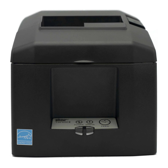
Page 8: Parts Identification And Nomenclature
2. Parts Identification and Nomenclature Printer cover Cover open lever Open to replace paper. Use this lever to open the Do not open while printing. printer cover. Power switch Control panel Turns the printer on Features lamps that indicate printer and off. -
Page 9: Setup
3. Setup 3-1. Connecting the Interface Cable to the PC 3-1-1. Parallel Cable Connect the parallel cable to a parallel port on your PC. 3-1-2. RS-232C Cable Connect the RS-232C cable to a RS-232C port on your PC. 3-1-3. USB Cable Connect the USB cable to a USB port on your PC. -
Page 10: Connecting The Interface Cable To The Printer
3-2. Connecting the Interface Cable to the Printer Printer cables are not included in the package. Obtain an appropriate cable that complies with the specifications beforehand. Because the appropriate interface cable differs depending on the system that you are connecting the printer to, contact the dealer that you bought the product from if you are unsure about what cable to use. - Page 11 3-2-2. RS-232C Interface Cable (1) Make sure that the AC adapter’s power cord is not connected to the outlet. (2) Connect the interface cable to the connector on the rear panel of the printer. (3) Tighten the connector screws. RS-232C interface cable 3-2-3.
- Page 12 3-2-4. Ethernet Cable To connect the cable, follow the procedure given below. (1) Make sure that the AC adapter’s power cord is not connected to the outlet. (2) Connect the Ethernet cable to the Ethernet port. Ethernet cable IFBD-HE07 Link disconnection detection feature The Ethernet interface model is equipped with a link disconnection detection feature.
-
Page 13: Connecting The Ac Adapter
3-3. Connecting the AC Adapter Note: Before connecting or disconnecting the AC adapter, make sure that the printer and all the devices connected to it are turned off. Then remove the power cord from the outlet. (1) Connect the AC adapter to the power cord. (2) Connect the AC adapter to the connector on the printer. -
Page 14: Turning The Power On
3-4. Turning the Power On Connect the power cord according to the procedure in section 3-3, “Connecting the AC Adapter”. Turn on the power switch, which is on the left side of the printer. The POWER lamp on the control panel will light. Power switch 3-5. -
Page 15: Loading A Paper Roll
3-6. Loading a Paper Roll Use a paper roll that complies with the printer specifications. (1) Push the cover open lever, and open the printer cover. Cover open lever (2) Load the paper roll into the printer in the direction indicated by the figure, and pull the leading edge of the paper straight toward you. - Page 16 3-6-1. Compliant Paper Roll Specifications 53 μm to 85 μm Paper thickness 79.5 ± 0.5 mm Paper width 57.5 ± 0.5 mm External dimensions • Roll diameter Max. f 83 mm +0.5 +0.5 • Take up paper roll width mm / 58 Inner diameter f 12 ±...
- Page 17 3-6-2. Changing the Paper Width When using 57.5 mm width paper rolls, attach the supplied paper roll guide to the printer. When you change the effective print width (paper roll width), change the printer utility’s memory switch setting. For details, see the printer utility help. (1) Insert the paper roll guide firmly into the slot in the printer labeled "r58"...
-
Page 18: Bluetooth Settings (For Bluetooth Interface Models Only )
Device name: Star Micronics (default) (4) In an iOS device, after pairing, the LED will automatically begin flashing blue, and the printer will be automatically connected. - Page 19 Device name: Star Micronics (default) It is recommended that you change the PIN code for greater security. For details regard changing the PIN code, please see the “Software Manual -Star Bluetooth Utility- ”. 3-7-3. Auto Connection Function (iOS only) Each time the wireless connection is disconnected while communicating with upper-level iOS devices including iPad over Bluetooth, it is necessary to move back to the Bluetooth setting screen in the upper-level iOS device and tap the desired printer name again to build a connection.
- Page 20 See the table below for details of Auto Connection setting. Auto Connection ON Auto Connection OFF Reconnecting without changing After the printer is turned on, it After turning on the printer, tap automatically connects to the last this printer's name on the Blue- the master device master device that was connected.
- Page 21 Setting from the Software After pairing your device and the TSP650II, change "Auto Connection" in the following application provided by our company. l iOS: Download "Star Setting Utility" from the following Web site. http://www.star-m.jp/prjump/000003.html l Android: Download "Star Setting Utility" from the following Web site.
- Page 22 3-7-5. Resetting Bluetooth Settings The following procedure explains how to initialize settings that you have changed such as the PIN code, device name, and so on. (1) While inserting a thin object such as the tip of a pen and holding down the RST button on the rear of the printer, turn on the printer's power switch.
-
Page 23: Setup Precautions
3-8. Setup Precautions Caution Symbol These symbols are located near the thermal print head. Because the thermal print head is hot immediately after printing, do not touch it. Static electricity can damage the thermal print head. To protect the thermal print head from static electricity, do not touch it. - Page 24 Below is a list of laws this device has been approved by. As Star Micronics is committed to constant innovation, revi- sions may be made without an announcement. Access the Star Micronics website for the latest listing of approvals.
-
Page 25: Attaching The Accessories
4. Attaching the Accessories The following accessories are necessary when mounting the printer to a wall. • Holder plate and two flangeless screws The following accessories are necessary when positioning the printer vertically. • Four rubber feet The following accessories do not necessarily have to be attached. Attach it if necessary. •... - Page 26 • Be sure to have qualified personnel install the specified screws and printer to the wall. Star is not responsible for any accidents or injuries that occur as a result of improper installation, misuse, or modifications. Especially when installing the printer at a high location, make sure that the printer is securely installed to the wall.
-
Page 27: Attaching The Rubber Feet
4-2. Attaching the Rubber Feet (1) Ensure that any soiling has been completely wiped off before attaching the rubber feet. (2) Attach the four rubber feet in the positions shown in the figure. 4-3. Switch Cover Installation It is not necessary to install the switch cover. Only install it if it is necessary for you. By installing the switch cover, the following become possible. -
Page 28: Adjusting The Near-End Sensor
5. Adjusting the Near-end Sensor Use the following procedure to adjust the near-end sensor so it is compatible with the size of paper roll you are using. Adjustment value according to the paper you are using Horizontal (standard) Layout Vertical Layout or Wall-Mount ø12 inner diameter / ø18 outer diameter core roll paper ø12 inner diameter / ø18 outer diameter core roll paper Paper Width... -
Page 29: Error Indicators
6. Error Indicators 6-1. Recoverable errors Check the recovery conditions. The printer can be recovered while maintaining its current status. Error description POWER ERROR Recovery condition Thermal head high Flashes at 1 sec- temperature detection The printer recovers automatically when the thermal head cools. ond intervals error The printer recovers when you close the cover. -
Page 30: Preventing And Removing Paper Jams
7. Preventing and Removing Paper Jams 7-1. Preventing Paper Jams To avoid paper jams and other problems, feed the paper at least 1 mm (8 dot lines) before printing. If you want to use the cutter, to avoid paper jams and other problems, we recommend a margin of at least 5 mm from the end of the printed area to the cutting position. -
Page 31: Releasing The Cutter Lock
7-3. Releasing the Cutter Lock If the auto cutter locks up, restart the printer by turning the power switch off and then back on. A typical locked cutter will be restored when you restart the printer. If restarting the printer does not release the locked cutter, follow the procedure below. Note 1: Be sure to turn off the printer before performing maintenance on the cutter. -
Page 32: Maintenance
8. Maintenance Accumulation of paper dust and dirt may cause the printer to not print portions of characters. To prevent such problems, perform periodic maintenance, such as removing paper dust from the paper transport sec- tion and removing the blackened paper dust from the thermal head surface. As a guideline, clean the printer every six months. - Page 33 http://www.starmicronics.com/support/ Rev. 2.1...
Need help?
Do you have a question about the TSP654IIBI and is the answer not in the manual?
Questions and answers