Table of Contents
Advertisement
Quick Links
INSTALLATION, OPERATING AND
SERVICE INSTRUCTIONS FOR
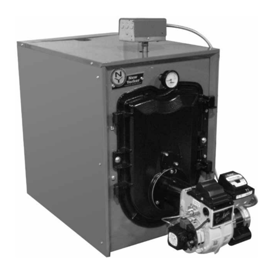
CI-HGS™-B SERIES
As an ENERGY STAR
Partner, New Yorker Boiler
Co. Inc. has determined
that the CI-HGS™-B Series
meets the ENERGY STAR
guidelines for energy
efficiency established by the
United States Environmental
Protection Agency (EPA).
9700609
For service or repairs to boiler, call your heating contractor or oil supplier. When seeking
information on boiler, provide Boiler Model Number and Serial Number as shown on Rating
Label located on top of the boiler.
Boiler Model Number
CI-HGS - _ _ _ B
Heating Contractor
Address
105753-02 - 1/16
3-PASS OIL BOILER
®
®
Boiler Serial Number
Installation Date
Phone Number
Price - $5.00
Advertisement
Table of Contents

Related Manuals for New Yorker CI-HGS-B Series


Summary of Contents for New Yorker CI-HGS-B Series
- Page 1 INSTALLATION, OPERATING AND SERVICE INSTRUCTIONS FOR CI-HGS™-B SERIES 3-PASS OIL BOILER As an ENERGY STAR ® Partner, New Yorker Boiler Co. Inc. has determined that the CI-HGS™-B Series meets the ENERGY STAR ® guidelines for energy efficiency established by the United States Environmental Protection Agency (EPA).
- Page 2 IMPORTANT INFORMATION - READ CAREFULLY All boilers must be installed in accordance with National, State and Local Plumbing, Heating and Electrical Codes and the regulations of the serving utilities. These Codes and Regulations may differ from this instruction manual. Authorities having jurisdiction should be consulted before installations are made.
- Page 3 DANGER DO NOT store or use gasoline or other flammable vapors or liquids in the vicinity of this or any other appliance. WARNING Improper installation, adjustment, alteration, service or maintenance can cause property damage, personal injury or loss of life. Failure to follow all instructions in the proper order can cause personal injury or death.
-
Page 4: Table Of Contents
WARNING This boiler contains very hot water under high pressure. DO NOT unscrew any pipe fittings nor attempt to disconnect any components of this boiler without positively assuring the water is cool and has no pressure. Always wear protective clothing and equipment when installing, starting up or servicing this boiler to prevent scald injuries. -
Page 7: Pre-Installation
SECTION II: PRE-INSTALLATION A. INSPECT SHIPMENT carefully for any signs of • 24” for flueway cleaning (CI-HGS-74B thru damage. CI-HGS-129B) • 30” for flueway cleaning (CI-HGS-167B) 1. All equipment is carefully manufactured, inspected b. Clearance from Jacket Left Side Panel - and packed. - Page 8 SECTION II: PRE-INSTALLATION (continued) 3. Determine type of space. Divide Volume by total NOTICE input of all appliances in space. If the result is greater than or equal to 50 ft /1000 BTU per hour, Clearance to venting is for single wall vent then it is considered an unconfined space.
- Page 9 SECTION II: PRE-INSTALLATION (continued) c. Horizontal ducts. Minimum free area of 1 b. Free area requirements need to consider the square inch per 2,000 BTU per hour input of all blocking effect of louvers, grilles, or screens equipment in space. Duct cross-sectional area protecting the openings.
-
Page 10: Packaged Boiler Assy. - Trim & Controls
SECTION III: PACKAGED BOILER ASSEMBLY - TRIM & CONTROLS A. REMOVE CRATE. Step 6. Lower pipe handles until front adjustable legs touch floor. If necessary, place wooden 1. Remove all fasteners at crate skid. blocks under front legs before lowering to 2. - Page 11 SECTION III: PACKAGED BOILER ASSEMBLY - TRIM & CONTROLS (continued) 1. TO OPEN BURNER SWING DOOR • Lift door off mounting bracket and set (see Figures 4A and 4B). aside. • Remove mounting bracket and hardware Step 1. Loosen but do not remove left side latching from left side.
- Page 12 SECTION III: PACKAGED BOILER ASSEMBLY - TRIM & CONTROLS (continued) Figure 4B: Top View - Burner Swing Door Mounted to Cast Iron Block Assembly (Jacket Removed for Clarity)
- Page 13 SECTION III: PACKAGED BOILER ASSEMBLY - TRIM & CONTROLS (continued) Step 1. From the fully open position, rotate Burner screw first. Use an alternating tightening Swing Door to the closed position. method from right side tap bolt to left side tap bolt to tighten door equally until sealed without Step 2.
- Page 14 SECTION III: PACKAGED BOILER ASSEMBLY - TRIM & CONTROLS (continued) Step b. Locate the relief valve piping supplied By design, cast bars on front section between the combustion chamber and between the left and with boiler. Apply thread sealant to all joints right side 2 and 3 pass flueway should make an...
- Page 15 SECTION III: PACKAGED BOILER ASSEMBLY - TRIM & CONTROLS (continued) c. Locate the Limit sensor inside Boiler Control. Carefully connect sensor into the Boiler Control circuit board by pressing connector on sensor unit into mating connector on circuit board (refer to Figure 40). Insert sensor through hole in circuit board and into immersion well until it rests against the bottom of the well as shown in Figure 6.
- Page 16 SECTION III: PACKAGED BOILER ASSEMBLY - TRIM & CONTROLS (continued) Step c. Apply sealant to 3/4” NPT thread on • Model CI-HGS-101B - To install flueway drain valve. Thread into 3/4” NPT tapping baffle in 3 pass on left side of boiler, hold on side outlet of tee.
- Page 17 SECTION III: PACKAGED BOILER ASSEMBLY - TRIM & CONTROLS (continued) Figure 9: Baffle Orientation in Flueways 8. Install oil burner. (See Figure 10 and Table 4) Step f. Align holes and install two (2) remaining cap screws. Level burner and fully tighten all three Step a.
- Page 18 SECTION III: PACKAGED BOILER ASSEMBLY - TRIM & CONTROLS (continued) Figure 10: Oil Burner Installation (Beckett shown) TABLE 4: BURNER-N-BOx BURNERS Boiler Model Burner Part Numbers CI-HGS-74B 106771-01 (Beckett), 106775-01 (Carlin) CI-HGS-101B 106772-01 (Beckett), 106776-01 (Carlin) CI-HGS-129B 106773-01 (Beckett), 106777-01 (Carlin) CI-HGS-167B 106774-01 (Beckett), 106778-01 (Carlin)
-
Page 19: Water Boiler Piping
3. If an indirect water heater is used, priority zoning can New Yorker Boiler Co. recommends sizing be used. Do not use priority zoning for Hydro-Air the system circulator to supply sufficient Systems. Refer to the Indirect Water Heater Installation, flow (GPM) to allow a 20°F temperature... - Page 22 SECTION IV: WATER BOILER PIPING (continued) Figure 11C: Recommended Piping for Combination Heating and Cooling (Refrigeration) System 5. If it is required to perform a long term pressure WARNING test of the hydronic system, the boiler should first be isolated from the system to avoid a pressure loss The use of a low water cut-off device, while not due to the escape of air trapped in the boiler.
-
Page 23: Indirect Water Heater Piping
SECTION V: INDIRECT WATER HEATER PIPING A. CONNECT INDIRECT DOMESTIC WATER 1. Refer to instructions furnished with Indirect Water HEATER PIPING as shown in Figure 12A and 12B. Heater for additional information. Also refer to Figures 11A and 11B. Figure 12A: Indirect Water Heater Piping w/Supply Side Circulator on Circulator Zoned Heating System Figure 12B: Indirect Water Heater Piping w/Supply Side Circulator on Zone Valve Zoned Heating System... -
Page 24: Natural Draft Venting (Chimney)
SECTION VI: NATURAL DRAFT VENTING (CHIMNEY) WARNING Vent this boiler according to these instructions. Failure to do so may cause products of combustion to enter the home resulting in severe property damage, personal injury or death. Insufficient Combustion Air Supply may result in the production and release of deadly carbon monoxide (CO) into the home which can cause severe personal injury or death. - Page 25 SECTION VI: NATURAL DRAFT VENTING (CHIMNEY) (continued) FIRECLAY TILE LINED CHIMNEY NOT LESS THAN 8" X 8" X 15' THIMBLE NOTE: ALL HORIZONTAL VENT PIPE SHOULD SLOPE UPWARD NOT SLOPE UP LESS THAN ONE INCH IN APPROX. FOUR FEET. 120° AIR GAP DRAFT REGULATOR 10 O'CLOCK...
- Page 26 SECTION VI: NATURAL DRAFT VENTING (CHIMNEY) (continued) B. CHIMNEY CONNECTOR 2. Minimum Draft at Breech (Canopy) – The draft induced by a chimney must create at least a 1. A chimney connector (vent pipe) is used to connect pressure of 0 (zero) inches water column (“ w.c.) the boiler to the base of the chimney.
- Page 27 SECTION VI: NATURAL DRAFT VENTING (CHIMNEY) (continued) cases, the chimney may have to be lined to prevent 3. Baffles – The efficiency of the boiler is based on the the corrosion of a masonry chimney. Consult insertion of flue baffles supplied with your product. with a chimney specialist knowledgeable on the Under no circumstances are other baffles to be used on requirements for chimney requirements in your area.
-
Page 28: Direct Venting / Air Intake Piping
SECTION VII: DIRECT VENTING / AIR INTAKE PIPING A. GENERAL GUIDELINES WARNING 1. Direct Vent system must be installed in accordance with these instructions and applicable provisions of local This venting system must be installed by a building codes. Contact your local fire and building qualified installer (an individual who has been officials on specific requirements for restrictions properly trained) or a licensed installer. - Page 29 SECTION VII: DIRECT VENTING / AIR INTAKE PIPING (continued) c. Not less than 4 ft from any door, window or gravity TABLE 6: WALL CUTOUT DIMENSIONS air inlet. d. Not less than 7 ft above grade when located above Boiler Model Direct Vent Conversion "L"...
- Page 30 SECTION VII: DIRECT VENTING / AIR INTAKE PIPING (continued) D. INSTALLING THE FLEX OIL VENT PIPE FROM THE VENT TERMINATION TO THE BOILER FLUE OUTLET 1. The venting system (vent pipe and all connectors) shall be installed in accordance with the applicable provisions of any local codes, and, in United States, requirements of NFPA 31- Standard for the Installation of Oil-Burning Equipment and NFPA 211 Standard for...
- Page 31 SECTION VII: DIRECT VENTING / AIR INTAKE PIPING (continued) TABLE 7: FLEx VENT / VENT TERMINATION PIPE DIAMETERS Vent Hood Flex Oil Vent Pipe Boiler Flue Outlet * Flue Outlet Collar to Boiler Model No. Inner Pipe Inner Pipe Diameter Collar OD (Inch) Vent Pipe Adapter (Inch) Diameter (Inch)
- Page 32 SECTION VII: DIRECT VENTING / AIR INTAKE PIPING (continued) 7. Apply sealant; firstly, between the stop bead and retainer bead at the end of the vent termination inner pipe; secondly, between the stop bead and retainer bead at the end of the appliance adapter. See Figure 8.
- Page 33 SECTION VII: DIRECT VENTING / AIR INTAKE PIPING (continued) WARNING DO NOT reduce size of air intake pipe. 3. Remove burner from carton. Secure burner to boiler with mounting hardware included with burner swing door. See Figure 26. 4. Remove knockout for 4" vent pipe collar from burner cover.
- Page 34 SECTION VII: DIRECT VENTING / AIR INTAKE PIPING (continued) 12. Assemble the vacuum relief valve balance weight onto 14. Install remainder of air intake piping to Direct Vent the gate. Refer to the vacuum relief valve manufacturer’s Termination air intake collar, securing each joint with instructions for details.
-
Page 35: Electrical
SECTION VIII: ELECTRICAL DANGER Positively assure all electrical connections are unpowered before attempting installation or service of electrical components or connections of the boiler or building. Lock out all electrical boxes with padlock once power is turned off. WARNING Failure to properly wire electrical connections to the boiler may result in serious physical harm. Electrical power may be from more than one source. - Page 38 SECTION VIII: ELECTRICAL (continued) NOTE: APPLY THIS BURNER SCHEMATIC TO APPROPRIATE WATER BOILER CONTROL SCHEMATIC, REFER TO FIGURES 27 AND 28. NOTE: APPLY THIS BURNER SCHEMATIC TO APPROPRIATE WATER BOILER CONTROL SCHEMATIC, REFER TO FIGURES 27 AND 28. NOTE: APPLY THIS BURNER SCHEMATIC TO APPROPRIATE WATER BOILER CONTROL SCHEMATIC, REFER TO FIGURES 27 AND 28.
-
Page 39: Oil Piping
SECTION IX: OIL PIPING A. GENERAL WARNING 1. Use flexible oil line(s) so the burner swing door Under no circumstances can copper with sweat can be opened without disconnecting the oil supply style connectors be used. piping. 2. A supply line fuel oil filter is recommended as a NOTICE minimum for all firing rates but a pleated paper fuel oil filter is recommended for the firing rates below... - Page 40 SECTION IX: OIL PIPING (continued) C. TWO PIPE OIL LINES 3. Under no circumstances is a manual shutoff valve to be located on the return line of a two pipe system. 1. For two piped systems, where more lift is required, Accidental closure of the return line will rupture the the two-stage fuel unit is recommended.
-
Page 41: System Start-Up
SECTION X: SYSTEM START-UP WARNING All boilers equipped with burner swing door have a potential hazard which can cause severe property damage, personal injury or loss of life if ignored. Before opening swing door, turn off service switch to boiler to prevent accidental firing of burner outside the combustion chamber. - Page 42 SECTION X: SYSTEM START-UP (continued) 2. PRESS RED RESET BUTTON on burner primary 3. Carlin Burners control, hold for ten (10) seconds and release to a. Remove nozzle line electrode assembly from reset the control. burner. 3. WATER BOILERS WITHOUT TANKLESS b.
- Page 44 SECTION X: SYSTEM START-UP (continued) which matches a value shown in Table 19 for a particular boiler/burner model. The zero calibration has been factory set; the upper left acorn nut locks retention head at “0” position. If the zero calibration has to be reset, follow the adjustment procedure, outlined at “Prepare Burner &...
- Page 45 SECTION X: SYSTEM START-UP (continued) G. ADJUST OIL BURNER WHILE 3. TURN ‘ON’ BURNER service switch and OPERATING. (flame present) allow burner to run until oil flows from vent fitting in a SOLID stream without air bubbles for 1. ADJUST DRAFT REGULATOR for a draft of approximately 10 seconds.
- Page 46 SECTION X: SYSTEM START-UP (continued) 4. FLAME FAILURE TEST CONTROLS. The CI-HGS-B boiler controls operate the burner 1. Check thermostat operation. Raise and lower automatically. If for unknown reasons the burner thermostat setting as required to start and stop ceases to fire and the reset button on the primary burner.
- Page 47 SECTION X: SYSTEM START-UP (continued) • Release the reset button. The yellow Conduct these tests with flame present, see light will turn off and the burner will start chart below. up again. Flame Detection Range • At burner start up, click the reset button Normal (0 - 1600 ohms) while the igniter is till on.
- Page 48 SECTION X: SYSTEM START-UP (continued) • 4. CHECK HIGH LIMIT Close hand valve in oil supply line. • a. Adjust system thermostat(s) to highest setting. Failure occurs, device enters Recycle Mode. b. Allow burner to run until boiler water • Device tries to restart system after temperature exceeds high limit setting.
-
Page 49: Operating
SECTION XI: OPERATING WATER BOILERS SEQUENCE OF OPERATION Water Boilers Without Tankless Heaters (Cold Start), Sequence Of Operation: a. The CI-HGS-B Boiler is equipped with an Intelligent Oil Boiler Control (cold start boiler control). The boiler control replaces the traditional electronic aquastat and circulator relays and adds energy saving thermal purge features. - Page 50 SECTION XI: OPERATING (continued) “I” Press and release the key on the Boiler Control to Cold Start Boiler Control change from one parameter to the next. Each setting Adjustment Mode Options will alternately flash between the relevant display code 140-240°F Adjust High Limit Setting and its corresponding value.
- Page 51 SECTION XI: OPERATING (continued) TABLE 11: CIRCULATOR PRE-PURGE TIME ExAMPLE, TABLE 12: DOMESTIC HOT WATER DEMAND, PARAMETER PP_= 2 MINUTES (PARAMETER ZC_= DH) ZC and ZR Call for Heat Circulator Status Call for Boiler Boiler Status, Terminal Priority System Heat Function Temp.
- Page 52 SECTION XI: OPERATING (continued) TABLE 13: ZONE REqUEST, PARAMETER ZC_= ZR TABLE 14: ExTERNAL LOW LIMIT, PARAMETER ZC_= ELL Call for Heat Circulator Status Call for Heat Circulator Status Input Input Output Output Input Input Output Output ii. When ZC_ is set equal to Zone Request (ZR) iii.
-
Page 53: Maintenance & Service Instructions
SECTION XII: MAINTENANCE AND SERVICE INSTRUCTIONS After boiler and system have been cleaned and WATER BOILERS: refilled as previously described, test the pH of 1. Filling of boiler and system. the water in the system. This can easily be done GENERAL —... - Page 54 SECTION XII: MAINTENANCE AND SERVICE INSTRUCTIONS (cont'd) 3. Always keep the manual fuel supply valve shut off ATTENTION TO BOILER WHILE NOT IN if the burner is shut down for an extended period of OPERATION time. NOTICE 4. To recondition the heating system in the fall season after a prolonged shut down, follow the instructions If boiler is not used during winter time, it must be outlined in Section X, System Start-Up, Paragraphs...
-
Page 55: Boiler Cleaning
SECTION XIII: BOILER CLEANING WARNING All boiler cleaning must be completed with burner service switch turned off. Boilers equipped with burner swing door have a potential hazard which can cause severe property damage, personal injury or loss of life if ignored. Before opening swing door, turn off service switch to boiler to prevent accidental firing of burner outside the combustion chamber. - Page 56 SECTION XIII: BOILER CLEANING (continued) Figure 42: Cleaning of Boiler Flueways WARNING The boiler must be connected to an approved chimney in good condition. Serious property damage could result if the boiler is connected to a dirty or inadequate chimney. The interior of the chimney flue must be inspected and cleaned before the start of the heating season and should be inspected periodically throughout the heating season for any obstructions.
- Page 57 Important Product Safety Information Refractory Ceramic Fiber Product Warning: The Repair Parts list designates parts that contain refractory ceramic fibers (RCF). RCF has been classified as a possible human carcinogen. When exposed to temperatures above 1805°F, such as during direct flame contact, RCF changes into crystalline silica, a known carcinogen.
-
Page 58: Trouble Shooting
SECTION XIV: TROUBLE SHOOTING COMBUSTION 6. WATER — Water in the fuel in large amounts will stall the fuel pump. Water in the fuel in smaller 1. NOZZLES — Although the nozzle is a relatively amounts will cause excessive wear on the pump, inexpensive device, its function is critical to the but more importantly water doesn’t burn. - Page 59 SECTION XIV: TROUBLE SHOOTING (continued) f. CAD cell defective. OIL PRIMARY CONTROL (Oil Primary) 1. Burner (Oil Primary) will not come on. g. Oil valve stuck open or closed. a. No power to Oil Primary. Note: The Safety Monitoring Circuit (SMC) is b.
- Page 60 SECTION XIV: TROUBLE SHOOTING (continued) b. If the Boiler Control detects an error it will flash "Err" (boiler control error) followed by a number. Use this text and number to identify the boiler problem and corrective action in Table 16 below. TABLE 16: BOILER CONTROL ERROR NUMBERS Display Status...
-
Page 61: Repair Parts
All CI-HGS™-B Series repair parts may be ordered through New Yorker Boiler Co., Inc., or its authorized distributors. Should you require assistance in locating a New Yorker Distributor in your area, or have questions regarding the availability of New Yorker products or repair parts, please contact: New Yorker Boiler Co., Inc., P.O. Box 10, Hatfield, PA 19440-0010,... - Page 63 SECTION XV: REPAIR PARTS (continued) Item Description Part No. CI-HGS-74B CI-HGS-101B CI-HGS-129B CI-HGS-167B 1. BARE BOILER ASSEMBLY Cast Iron Section Assembly, 2 Section 103071-02 Cast Iron Section Assembly, 3 Section 103071-03 Cast Iron Section Assembly, 4 Section 103071-04 Spanner Bar Assembly w/Threaded Inserts, Painted, w/Hardware Installed (Includes Items 1C, 1D, 1E and 1F - Qty 1 ea.) 1-1/4"...
- Page 65 SECTION XV: REPAIR PARTS (continued) Item Description Part No. CI-HGS-74B CI-HGS-101B CI-HGS-129B CI-HGS-167B 2. JACKET ASSEMBLY Jacket Front Panel Assembly w/Insulation 102403-01 Jacket Rear Panel Assembly w/Insulation 105729-01 5/16” -18 x 3” Lg. Tap End Stud, Plain 100046-01 5/8” O.D. x 2-5/32” Lg. Jacket Spacer 100035-01 5/16”...
- Page 67 SECTION XV: REPAIR PARTS (continued) Item Description Part No. CI-HGS-74B CI-HGS-101B CI-HGS-129B CI-HGS-167B 3. WATER BOILERS - TRIM AND CONTROLS Beckett Burner-N-Box: CI-HGS-74B Spec No. NY2806 106771-01 CI-HGS-101B Spec No. NY2807 106772-01 CI-HGS-129B Spec No. NY2808 106773-01 CI-HGS-167B Spec No. NY2809 106774-01 Beckett Nx Oil Burner w/Gasket: CI-HGS-129B Spec No.
- Page 69 SECTION XV: REPAIR PARTS (continued) BECKETT AFG OIL BURNER PART NOS. FOR CI-HGS-B SERIES BOILERS NATURAL DRAFT APPLICATIONS NOTE: When ordering parts always give the serial and model numbers shown on the boiler and burner. Also provide the name of the part(s) and part number as listed below.
- Page 71 SECTION XV: REPAIR PARTS (continued) BECKETT Nx OIL BURNER PART NOS. FOR CI-HGS-B SERIES BOILERS DIRECT VENT APPLICATIONS NOTE: When ordering parts always give the serial and model numbers shown on the boiler and burner. Also provide the name of the part(s) and part number as listed below.
- Page 72 5" Dia. x 20 ft. FOVP-520 100214-02 CARLIN OIL BURNER PART NUMBERS FOR CI-HGS-B SERIES BOILERS NOTE: When ordering parts always give the serial and model numbers shown on the boiler and burner. Refer to Carlin Model EZ Oil burner-Instruction Manual (Form #MNEZ123) for an exploded view of the burner and a list of spare parts.
-
Page 75: Appendix B Low Water Cut Off
APPENDIX B: LOW WATER CUT-OFF (LWCO) ON HOT WATER BOILERS WARNING DO NOT ATTEMPT to cut factory wires to install an aftermarket Low Water Cut Off (LWCO). Only use connections specifically identified for Low Water Cut Off. In all cases, follow the Low Water Cut Off (LWCO) manufacturer's instructions. minimum When connection must have a... - Page 76 APPENDIX B: LOW WATER CUT-OFF (LWCO) ON HOT WATER BOILERS (continued) How to Test A 24 VAC LWCO is used primarily for gas fired boilers where a 24 volt control circuit exists within the Shut off fuel supply. Lower water level until water boiler.
Need help?
Do you have a question about the CI-HGS-B Series and is the answer not in the manual?
Questions and answers