Table of Contents
Advertisement
Quick Links
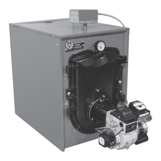
Installation, Operating and Service Instructions for
CI-HGS
Models:
• CI-HGS-74E
• CI-HGS-101E
• CI-HGS-123E
• CI-HGS-160E
Manual Contents
General Information . . . . . . . . . . . . . . . . . . . . . . 5
Pre-installation . . . . . . . . . . . . . . . . . . . . . . . . . . 7
Packaged Boiler Assy .- Trim & Controls . . . . 10
Water Boiler Piping . . . . . . . . . . . . . . . . . . . . . 19
Indirect Water Heater Piping . . . . . . . . . . . . . . 23
Natural Draft Venting (Chimney) . . . . . . . . . . . 24
Direct Venting/Air Intake Piping . . . . . . . . . . . 28
Electrical . . . . . . . . . . . . . . . . . . . . . . . . . . . . . . 35
Oil Piping . . . . . . . . . . . . . . . . . . . . . . . . . . . . . 39
System Start-Up . . . . . . . . . . . . . . . . . . . . . . . . 41
Operating . . . . . . . . . . . . . . . . . . . . . . . . . . . . . 49
Maintenance and Service . . . . . . . . . . . . . . . . 53
Boiler Cleaning . . . . . . . . . . . . . . . . . . . . . . . . 55
Troubleshooting . . . . . . . . . . . . . . . . . . . . . . . . 58
Service Parts . . . . . . . . . . . . . . . . . . . . . . . . . . 61
Burner Specifications . . . . . . . . . . . . . . . . . . . 72
Appendix A After Market LWCO . . . . . . . . . . . 74
As an ENERGY STAR
®
Co. Inc. has determined that the CI-HGS-E series,
meets the ENERGY STAR
efficiency established by the United States
Environmental Protection Agency (EPA).
105753-06 - 9/19
TM
Page
Partner, New Yorker Boiler
guidelines for energy
®
-E
• High Efficiency
• Oil-Fired, 3-Pass
• Water Boiler
• Natural Draft or Direct Vent
(123E and 160E)
9700609
Advertisement
Table of Contents

Related Manuals for New Yorker CI-HGS-E


Summary of Contents for New Yorker CI-HGS-E
-
Page 1: Table Of Contents
Appendix A After Market LWCO . . . . . . . . . . . 74 As an ENERGY STAR Partner, New Yorker Boiler ® Co. Inc. has determined that the CI-HGS-E series, 9700609 meets the ENERGY STAR guidelines for energy ®... - Page 2 Installation, Operating & Service Manual CI-HGS-E IMPORTANT INFORMATION - READ CAREFULLY All boilers must be installed in accordance with National, State and Local Plumb- ing, Heating and Electrical Codes and the regulations of the serving utilities . These Codes and Regulations may differ from this instruction manual . Authorities having jurisdiction should be consulted before installations are made .
- Page 3 Installation, Operating & Service Manual CI-HGS-E DANGER DO NOT store or use gasoline or other flammable vapors or liquids in the vicinity of this or any other appliance. WARNING • Improper installation, adjustment, alteration, service or maintenance can cause property damage, personal injury or loss of life.
- Page 4 Installation, Operating & Service Manual CI-HGS-E WARNING • This boiler contains very hot water under high pressure. DO NOT unscrew any pipe fittings nor attempt to disconnect any components of this boiler without positively assuring the water is cool and has no pressure.
-
Page 5: General Information
Installation, Operating & Service Manual CI-HGS-E General Information 105753-06 - 9/19... - Page 6 Installation, Operating & Service Manual CI-HGS-E General Information (continued) Table 1A Dimensions See Figure 1 Water Content - Heat Transfer Surface Area Actual Shipping Boiler Model No. Gallons - Sq. Ft. Weight (LB.) “A” “B” “C” CI-HGS-74E/101E 17” 24” 5”...
-
Page 7: Pre-Installation
1. Listed clearances comply with American National Standard ANSI/NFPA 31, Standard for the Installation of Oil Burning Equipment. 2. CI-HGS-E boilers can be installed in rooms with clearances from combustible material as listed above. Listed clearances cannot be reduced for alcove or closet installations. - Page 8 Oil Burning Equipment. ANSI/NFPA 31 standard. 2. CI-HGS-E boilers can be installed in rooms with clearances from combustible material as listed above. Listed clearances cannot be reduced for alcove or closet installations.
- Page 9 Installation, Operating & Service Manual CI-HGS-E Pre-Installation (continued) b. Free area requirements need to consider the c. Horizontal ducts. Minimum free area of 1 blocking effect of louvers, grilles, or screens square inch per 2,000 BTU per hour input of protecting the openings.
-
Page 10: Packaged Boiler Assy .- Trim & Controls
Installation, Operating & Service Manual CI-HGS-E Packaged Boiler Assembly - Trim & Controls Step 6. Lower pipe handles until front A . REMOVE CRATE . adjustable legs touch floor. If necessary, 1. Remove all fasteners at crate skid. place wooden blocks under front legs 2. - Page 11 Installation, Operating & Service Manual CI-HGS-E Packaged Boiler Assembly - Trim & Controls (continued) To reverse hinge arrangement (see 1. TO OPEN BURNER SWING DOOR Figure 4A): (see Figures 4A and 4B). • Lift door off mounting bracket and set Step 1.
- Page 12 Installation, Operating & Service Manual CI-HGS-E Packaged Boiler Assembly - Trim & Controls (continued) Figure 4B: Top View - Burner Swing Door Mounted to Cast Iron Block Assembly (Jacket Removed for Clarity) 105753-06 - 9/19...
- Page 13 Installation, Operating & Service Manual CI-HGS-E Packaged Boiler Assembly - Trim & Controls (continued) 3. To close Burner Swing Door (see Figures 4A left side tap bolt to tighten door equally until and 4B): sealed without applying excessive torque. Never tighten left side flange bolt first or Step 1.
- Page 14 Installation, Operating & Service Manual CI-HGS-E Packaged Boiler Assembly - Trim & Controls (continued) Step b. Locate the relief valve piping By design, cast bars on front section between supplied with boiler. Apply thread the combustion chamber and between the left sealant to all joints prior to assembly.
- Page 15 Installation, Operating & Service Manual CI-HGS-E Packaged Boiler Assembly - Trim & Controls (continued) c. Locate the Limit sensor inside Boiler Step c. Apply sealant to 3/4” NPT thread Control. Carefully connect sensor into the on drain valve. Thread into 3/4” NPT Boiler Control circuit board by pressing tapping on side outlet of tee.
- Page 16 Installation, Operating & Service Manual CI-HGS-E Packaged Boiler Assembly - Trim & Controls (continued) 5. Connect Field Wiring. • Model CI-HGS-101E - To install flueway baffle in 3 pass on left side Step a. Connect the field wiring from of boiler, hold baffle with word “Left”...
- Page 17 Installation, Operating & Service Manual CI-HGS-E Packaged Boiler Assembly - Trim & Controls (continued) Figure 9: Baffle Orientation in Flueways 8. Install oil burner . (See Figure 10 and Table 4) Step f. Align holes and install two (2) remaining cap screws.
- Page 18 Installation, Operating & Service Manual CI-HGS-E Packaged Boiler Assembly - Trim & Controls (continued) Figure 10: Oil Burner Installation (Beckett shown) Table 4: Burner-N-Box Burners Boiler Model Burner Part Numbers CI-HGS-74E 106771-01 (Beckett), 106775-01 (Carlin) CI-HGS-101E 106772-01 (Beckett), 106776-01 (Carlin)
-
Page 19: Water Boiler Piping
Installation, Operating, and Service Instructions most restrictive single zone should be used to for additional information. determine maximum pressure drop. 4. The CI-HGS-E is designed to withstand thermal shock from return water temperatures as low as CAUTION 100°F, but prolonged return temperatures of below Maintain minimum ½... - Page 20 Installation, Operating & Service Manual CI-HGS-E Water Boiler Piping (continued) 105753-06 - 9/19...
- Page 21 Installation, Operating & Service Manual CI-HGS-E Water Boiler Piping (continued) 105753-06 - 9/19...
- Page 22 Installation, Operating & Service Manual CI-HGS-E Water Boiler Piping (continued) Figure 11C: Recommended Piping for Combination Heating and Cooling (Refrigeration) System 5. If it is required to perform a long term WARNING pressure test of the hydronic system, the The use of a low water cut-off device, while...
-
Page 23: Indirect Water Heater Piping
Installation, Operating & Service Manual CI-HGS-E Indirect Water Heater Piping A . CONNECT INDIRECT DOMESTIC WATER 1. Refer to instructions furnished with Indirect HEATER PIPING as shown in Figure 12A and Water Heater for additional information. 12B. Also refer to Figures 11A and 11B. -
Page 24: Natural Draft Venting (Chimney)
Under no circumstances shall a chimney 3. The CI-HGS-E shall be vented into any of the following: of this condition be used until it meets the requirements a. Masonry or metal chimney. Build and install in of NFPA 211 or CSA B139. - Page 25 Installation, Operating & Service Manual CI-HGS-E Natural Draft Venting (Chimney) (continued) FIRECLAY TILE LINED CHIMNEY NOT LESS THAN 8" X 8" X 15' THIMBLE NOTE: ALL HORIZONTAL VENT PIPE SHOULD SLOPE UPWARD NOT SLOPE UP LESS THAN ONE INCH IN APPROX.
- Page 26 Installation, Operating & Service Manual CI-HGS-E Natural Draft Venting (Chimney) (continued) B . CHIMNEY CONNECTOR 2. Minimum Draft at Breech (Canopy) – The draft induced by a chimney must create at least a 1. A chimney connector (vent pipe) is used to pressure of 0 (zero) inches water column (“...
- Page 27 Installation, Operating & Service Manual CI-HGS-E Natural Draft Venting (Chimney) (continued) 2. NFPA 31 and CSA B139 have information to 3. Baffles – The efficiency of the boiler is based on the help the installer make an appropriate choice insertion of flue baffles supplied with your product.
-
Page 28: Direct Venting/Air Intake Piping
Installation, Operating & Service Manual CI-HGS-E Direct Venting / Air Intake Piping A . GENERAL GUIDELINES WARNING 1. Direct Vent system must be installed in accordance This venting system must be installed by a with these instructions and applicable provisions qualified installer (an individual who has been of local building codes. - Page 29 Installation, Operating & Service Manual CI-HGS-E Direct Venting / Air Intake Piping (continued) f. Not less than 1 ft from the nearest surface of Table 6: Wall Cutout Dimensions the terminal to a roof soffit. g. Not directly above, or, not less than 6 ft Direct Vent "L"...
- Page 30 7. Verify that flex vent pipe diameter and vent the joint between the vent termination outer pipe termination inner pipe diameter correspond to and the vent tee body. a particular direct vent configuration CI-HGS-E boiler model (see Table 7). Figure 20: FDVS Component Breakdown...
- Page 31 Installation, Operating & Service Manual CI-HGS-E Direct Venting / Air Intake Piping (continued) Table 7: Flex Vent / Vent Termination Pipe Diameters Vent Hood Flex Oil Vent Pipe Boiler Flue Outlet * Flue Outlet Collar to Boiler Model No. Inner Pipe...
- Page 32 Installation, Operating & Service Manual CI-HGS-E Direct Venting / Air Intake Piping (continued) vent termination inner pipe, and, from the end of the appliance adapter. 7. Apply sealant; firstly, between the stop bead and retainer bead at the end of the vent termination inner pipe;...
- Page 33 Installation, Operating & Service Manual CI-HGS-E Direct Venting / Air Intake Piping (continued) WARNING DO NOT reduce size of air intake pipe. 3. Remove burner from carton. Secure burner to boiler with mounting hardware included with burner swing door. See Figure 26.
- Page 34 Installation, Operating & Service Manual CI-HGS-E Direct Venting / Air Intake Piping (continued) 12. Assemble the vacuum relief valve balance weight 14. Install remainder of air intake piping to Direct onto the gate. Refer to the vacuum relief valve Vent Termination air intake collar, securing manufacturer’s instructions for details.
-
Page 35: Electrical
Installation, Operating & Service Manual CI-HGS-E Electrical DANGER Positively assure all electrical connections are unpowered before attempting installation or service of electrical components or connections of the boiler or building. Lock out all electrical boxes with padlock once power is turned off. - Page 36 Installation, Operating & Service Manual CI-HGS-E Electrical (continued) 105753-06 - 9/19...
- Page 37 Installation, Operating & Service Manual CI-HGS-E Electrical (continued) 105753-06 - 9/19...
- Page 38 Installation, Operating & Service Manual CI-HGS-E Electrical (continued) NOTE: APPLY THIS BURNER SCHEMATIC TO APPROPRIATE WATER BOILER CONTROL SCHEMATIC, REFER TO FIGURES 27 AND 28. NOTE: APPLY THIS BURNER SCHEMATIC TO APPROPRIATE WATER BOILER CONTROL SCHEMATIC, REFER TO FIGURES 27 AND 28.
-
Page 39: Oil Piping
Installation, Operating & Service Manual CI-HGS-E Oil Piping A . GENERAL WARNING 1. Use flexible oil line(s) so the burner swing door Under no circumstances can copper with sweat can be opened without disconnecting the oil style connectors be used. - Page 40 Installation, Operating & Service Manual CI-HGS-E Oil Piping (continued) C . TWO PIPE OIL LINES 3. Under no circumstances is a manual shutoff valve to be located on the return line of a two 1. For two piped systems, where more lift pipe system.
-
Page 41: System Start-Up
Installation, Operating & Service Manual CI-HGS-E System Start-Up WARNING All boilers equipped with burner swing door have a potential hazard which can cause severe property damage, personal injury or loss of life if ignored. Before opening swing door, turn off service switch to boiler to prevent accidental firing of burner outside the combustion chamber. - Page 42 Installation, Operating & Service Manual CI-HGS-E System Start-Up (continued) g. SLIGHTLY OPEN FLAME OBSERVATION 2. PRESS RED RESET BUTTON on burner PORT COVER on burner swing door, primary control, hold for ten (10) seconds and enough to insert draft gauge probe later.
- Page 43 Installation, Operating & Service Manual CI-HGS-E System Start-Up (continued) 105753-06 - 9/19...
- Page 44 Installation, Operating & Service Manual CI-HGS-E System Start-Up “stamped key” in the retention head collar (continued) lines up with the “keyway” in the nozzle adapter, when mounting the retention head. See Figure 35. j. To re-install the nozzle line assembly, reverse procedure outlined in steps f thru b.
- Page 45 Installation, Operating & Service Manual CI-HGS-E System Start-Up (continued) F . START OIL BURNER . c. To check the cut-off pressure, deadhead a reliable pressure gauge onto the copper 1. Open vent fitting on fuel pump. connector tube attached to the nozzle port.
- Page 46 4. FLAME FAILURE seat, and wipe both with a clean cloth until The CI-HGS-E boiler controls operate the clean, then replace and readjust oil pressure. burner automatically. If for unknown reasons If dripping or after burn persist replace fuel the burner ceases to fire and the reset button pump.
- Page 47 Installation, Operating & Service Manual CI-HGS-E System Start-Up (continued) the control can only be reset three times. The reset count returns to zero each time a call for heat is successfully completed. T-T Jumper: Select models have pre- installed T-T jumper. DO NOT remove jumper.
- Page 48 Installation, Operating & Service Manual CI-HGS-E System Start-Up (continued) • After third Recycle Mode trial, safety • Make sure power is on to the controls. switch locks out within safety switch • Make sure limit control is closed. timing indicated on label and control •...
-
Page 49: Operating
Operating A . WATER BOILERS SEQUENCE OF OPERATION 1. Water Boilers Without Tankless Heaters (Cold Start), Sequence Of Operation: a. The CI-HGS-E Boiler is equipped with an Intelligent Oil Boiler Control (cold start boiler control). The boiler control replaces the... - Page 50 Installation, Operating & Service Manual CI-HGS-E Operating (continued) d. To return to the normal operating mode from “I” Press and release the key on the Boiler Control the Adjustment Mode, when the “bc” option to change from one parameter to the next. Each is displayed, press either the Up ñ...
- Page 51 ZC output functionality to help the temperature is less than 140°F. This feature CI-HGS-E integrate into each installation helps save energy by satisfying home heating more effectively. The ZC output can...
- Page 52 Installation, Operating & Service Manual CI-HGS-E Operating (continued) Table 13: Zone Request, Parameter ZC_= ZR Table 14: External Low Limit, Parameter ZC_= ELL Call for Heat Circulator Status Call for Heat Circulator Status Input Input Output Output Input Input Output...
-
Page 53: Maintenance And Service
Installation, Operating & Service Manual CI-HGS-E Maintenance and Service Instructions o. Refill the system with fresh water. A . WATER BOILERS: 1. Filling of boiler and system. 3. Add appropriate boiler water treatment compounds as recommended by your GENERAL — In a hot water heating system, qualified water treatment company. - Page 54 Installation, Operating & Service Manual CI-HGS-E Maintenance and Service Instructions (continued) 2. Spray inside surfaces with light lubricating or IMPORTANT crankcase oil using gun with extended stem so as to reach all corners. IF, DURING NORMAL OPERATION, IT IS NECESSARY TO ADD MORE WATER THAN 3.
-
Page 55: Boiler Cleaning
Installation, Operating & Service Manual CI-HGS-E Boiler Cleaning WARNING All boiler cleaning must be completed with burner service switch turned off. Boilers equipped with burner swing door have a potential hazard which can cause severe property damage, personal injury or loss of life if ignored. - Page 56 Installation, Operating & Service Manual CI-HGS-E Boiler Cleaning (continued) Figure 42: Cleaning of Boiler Flueways WARNING The boiler must be connected to an approved chimney in good condition. Serious property damage could result if the boiler is connected to a dirty or inadequate chimney. The interior of the chimney flue must be inspected and cleaned before the start of the heating season and should be inspected periodically throughout the heating season for any obstructions.
- Page 57 Installation, Operating & Service Manual CI-HGS-E Boiler Cleaning (continued) Important Product Safety Information: Refractory Ceramic Fiber Product WARNING Some boiler components use materials that contain refractory ceramic fibers (RCF). RCF has been classified as a possible human carcinogen. When exposed to elevated temperatures, RCF may change into crystalline silica, a known carcinogen.
-
Page 58: Troubleshooting
Installation, Operating & Service Manual CI-HGS-E Troubleshooting A . COMBUSTION and produce a poor spray pattern from the nozzle. The smaller the firing rate, the smaller 1. NOZZLES — Although the nozzle is a relatively the slots become in the nozzle and the more... - Page 59 Installation, Operating & Service Manual CI-HGS-E Troubleshooting (continued) 3. Control locks out after Trial For Ignition (TFI). NOTICE: CHECK TEST PROCEDURE. A very good test for isolating fuel side problems is to a. No oil to burner. disconnect the fuel system and with a 24" length b.
- Page 60 Installation, Operating & Service Manual CI-HGS-E Troubleshooting (continued) a. If an Error Code “Err” IS NOT displayed b. If the Boiler Control detects an error it will on the Boiler Control: In this circumstance, flash "Err" (boiler control error) followed Table 15 can be used to determine the by a number.
-
Page 61: Service Parts
CI-HGS-E Service Parts All CI-HGS™-E Series repair parts may be ordered through New Yorker Boiler Co., Inc., or its authorized distributors. Should you require assistance in locating a New Yorker Distributor in your area, or have questions regarding the availability of New Yorker products or repair parts, please contact: New Yorker Boiler Co., Inc., P.O. Box 3005, Lancaster, PA 17604-3005, ATTN: Customer Service Department. - Page 62 Installation, Operating & Service Manual CI-HGS-E Service Parts (continued) 105753-06 - 9/19...
- Page 63 Installation, Operating & Service Manual CI-HGS-E Service Parts (continued) CI-HGS-E Bare Boiler Assembly Item Description Part Number CI-HGS-74E CI-HGS-101E CI-HGS-123E CI-HGS-160E 109554-02 Block Assembly Includes: Block 109554-03 Assembly and Smoke Box 109554-04 Smoke Box Includes: Sealant, 109555-01 and Hardware Burner Swing...
- Page 64 Installation, Operating & Service Manual CI-HGS-E Service Parts (continued) 105753-06 - 9/19...
- Page 65 Installation, Operating & Service Manual CI-HGS-E Service Parts (continued) CI-HGS-E Water Trim Item Description Part Number CI-HGS-74E CI-HGS-101E CI-HGS-123E CI-HGS-160E 108297-02 Complete Jacket Carton Includes: 108297-03 Labels and Hardware 108297-04 109553-02 Wrap Around Insulation 109553-03 109553-04 Temperature & Pressure Gauge...
- Page 66 Clamp, Inner Pipe FDVS-5, Half 4. FLEX OIL VENT PIPE FOR DIRECT VENT 5" Dia. x 10 ft. FOVP-510 100212-02 Not Shown 5" Dia. x 20 ft. FOVP-520 100214-02 5 . CI-HGS-E Oil Burners Item Description Part Number CI-HGS-74E CI-HGS-101E CI-HGS-123E...
- Page 67 Installation, Operating & Service Manual CI-HGS-E Service Parts (continued) 105753-06 - 9/19...
- Page 68 CI-HGS-E Service Parts (continued) BECKETT AFG OIL BURNER PART NOS . FOR CI-HGS-E SERIES BOILERS NATURAL DRAFT APPLICATIONS NOTE: When ordering parts always give the serial and model numbers shown on the boiler and burner. Also provide the name of the part(s) and part number as listed below.
- Page 69 Installation, Operating & Service Manual CI-HGS-E Service Parts (continued) 105753-06 - 9/19...
- Page 70 Installation, Operating & Service Manual CI-HGS-E Service Parts (continued) 105753-06 - 9/19...
- Page 71 CI-HGS-E Service Parts (continued) BECKETT NX OIL BURNER PART NOS . FOR CI-HGS-E SERIES BOILERS DIRECT VENT APPLICATIONS NOTE: When ordering parts always give the serial and model numbers shown on the boiler and burner. Also provide the name of the part(s) and part number as listed below.
-
Page 72: Burner Specifications
Installation, Operating & Service Manual CI-HGS-E Burner Specifications 105753-06 - 9/19... - Page 73 Installation, Operating & Service Manual CI-HGS-E Burner Specifications (continued) 105753-06 - 9/19...
-
Page 74: Appendix A After Market Lwco
Installation, Operating & Service Manual CI-HGS-E Appendix A After Market Low Water Cut-off (LWCO) on Hot Boilers WARNING DO NOT ATTEMPT to cut factory wires to install an aftermarket Low Water Cut Off (LWCO). Only use connections specifically identified for Low Water Cut Off. - Page 75 Installation, Operating & Service Manual CI-HGS-E Appendix A After Market Low Water Cut-off (LWCO) on Hot Boilers (continued) A 24 VAC LWCO is used primarily for gas fired How to Test boilers where a 24 volt control circuit exists within Shut off fuel supply.
- Page 76 Installation, Operating & Service Manual CI-HGS-E SERVICE RECORD DATE SERVICE PERFORMED __________________________________________________________________________________________________ __________________________________________________________________________________________________ __________________________________________________________________________________________________ __________________________________________________________________________________________________ __________________________________________________________________________________________________ __________________________________________________________________________________________________ __________________________________________________________________________________________________ __________________________________________________________________________________________________ __________________________________________________________________________________________________ __________________________________________________________________________________________________ __________________________________________________________________________________________________ __________________________________________________________________________________________________ __________________________________________________________________________________________________ __________________________________________________________________________________________________ __________________________________________________________________________________________________ __________________________________________________________________________________________________ __________________________________________________________________________________________________ __________________________________________________________________________________________________ __________________________________________________________________________________________________ __________________________________________________________________________________________________ __________________________________________________________________________________________________ __________________________________________________________________________________________________ __________________________________________________________________________________________________ __________________________________________________________________________________________________ __________________________________________________________________________________________________ __________________________________________________________________________________________________ __________________________________________________________________________________________________ __________________________________________________________________________________________________ __________________________________________________________________________________________________...
Need help?
Do you have a question about the CI-HGS-E and is the answer not in the manual?
Questions and answers