Table of Contents
Advertisement
INSTALLATION, OPERATING
Installing contractor and homeowner should read and be informed as to the proper installation and operation of this boiler.
The manufacturer will not be responsible for improper installation or operation. This manual and all associated instruction
material should be conspicuously posted near the boiler.
For service or repairs to boiler, call your heating contractor. When seeking information on boiler,
provide Boiler Model Number and Serial Number as shown on Rating Label.
Boiler Model Number
CGS _ 0C
Heating Contractor
Address
104823-02 - 4/14
AND
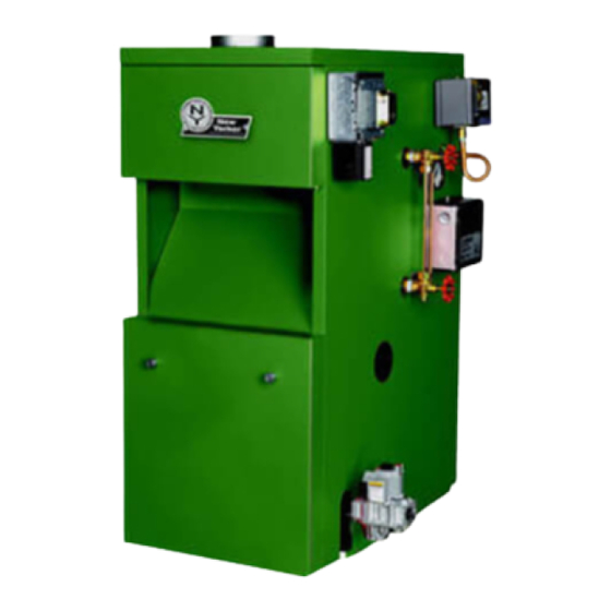
CGS-C™ SERIES
GAS BOILER
9700609
BEFORE INSTALLATION: READ THIS MANUAL
SAVE THESE INSTRUCTIONS
Boiler Serial Number
Installation Date
Phone Number
Price - $5.00
Advertisement
Table of Contents

Subscribe to Our Youtube Channel
Related Manuals for New Yorker CGS-C Series


Summary of Contents for New Yorker CGS-C Series
- Page 1 INSTALLATION, OPERATING SERVICE INSTRUCTIONS CGS-C™ SERIES GAS BOILER 9700609 BEFORE INSTALLATION: READ THIS MANUAL SAVE THESE INSTRUCTIONS Installing contractor and homeowner should read and be informed as to the proper installation and operation of this boiler. The manufacturer will not be responsible for improper installation or operation. This manual and all associated instruction material should be conspicuously posted near the boiler.
- Page 2 WARNINGS FOR THE HOMEOWNER FOLLOW ALL INSTRUCTIONS and warnings DO NOT BLOCK AIR FLOW into or around the printed in this manual and posted on the boiler. boiler. Insufficient air may cause the boiler to produce carbon monoxide or start a fire. INSPECT THE BOILER ANNUALLY.
- Page 3 WARNINGS FOR THE INSTALLER READ THIS ENTIRE MANUAL before attempting INSTALL ALL GUARDS, cover plates, and installation, start-up, or service. Improper enclosures before operating the boiler. installation, adjustment, alteration, service, SIZE THE BOILER PROPERLY relative to the or maintenance may cause serious property design heat load or, if using domestic hot water damage, personal injury, or death.
-
Page 4: Table Of Contents
TABLE OF CONTENTS Product Description..................Specifications.................... III. Pre-Installation................... Locating the Boiler..................Air for Combustion & Ventilation..............Venting....................... 11 VII. Gas Piping....................14 VIII. System Piping.................... 15 Indirect Water Heater Piping..............18 Electrical....................19 System Start-Up..................25 XII. Service Instructions................... 30 XIII. -
Page 5: Ii. Specifications
II. Specifications FIGURE 1: CGS-C BOILERS - GENERAL CONFIGURATION TABLE 1: CGS-C SPECIFICATIONS Recommended Min. Water Volume Approx. Dimensions (in inches) Round (Gal.) Boiler Shipping Chimney Size Conn. Model Weight Steam (Diameter x Height) (NPT) Lbs. Boiler CGS30C 12¾ 33-3/4 4"... -
Page 6: Iv. Locating The Boiler
I. Pre-Installation 1) Safe, reliable operation of this boiler depends upon installation by a professional heating contractor in strict accordance with this manual and the requirements of the authority having jurisdiction. • In the absence of an authority having jurisdiction, installation must be in accordance with this manual and the National Fuel Gas Code, ANSI Z223.1/NFPA 54. -
Page 7: V. Air For Combustion & Ventilation
IV. Locating the Boiler (continued) FIGURE 2: CGS-C BOILERS - CLEARANCES TO ALL TYPES OF COMBUSTIBLE CONSTRUCTION AND NONCOMBUSTIBLE CEILINGS, WALLS, AND DOORS. 4) Do not install this boiler in a location where gasoline or other flammable vapors or liquids will be stored or used. Do not install this boiler in an area where large amounts of airborne dust will be present, such as a workshop. 5) The boiler should be located as close to the chimney as possible. - Page 8 V. Air for Combustion & Ventilation (continued) For Buildings of Other than Unusually Tight Construction 1) Determine whether the boiler is to be installed in a confined space - A confined space is defined by the National Fuel Gas Code as having a volume less than 50 cubic feet per 1000 BTU/hr input of all appliances installed in that space. To determine whether the boiler room is a confined space: a.
- Page 9 V. Air for Combustion & Ventilation (continued) FIGURE 3: BOILER INSTALLED IN CONFINED SPACE, ALL AIR FROM INSIDE FIGURE 4: ALL AIR FROM OUTDOORS, VENTILATED CRAWL SPACE AND ATTIC FIGURE 5: ALL AIR FROM OUTDOORS, VIA VENTILATED ATTIC...
- Page 10 V. Air for Combustion & Ventilation (continued) FIGURE 6: ALL AIR FROM OUTDOORS, USING OPENINGS INTO BOILER ROOM FIGURE 7: ALL AIR FROM OUTDOORS, USING HORIZONTAL DUCTS INTO BOILER ROOM...
-
Page 11: Vi. Venting
• In some very restrictive cases, CGS-C series boilers may be vented into an exterior ceramic lined masonry chimney. See the National Fuel Gas Code for information on when exterior chimneys may be used. - Page 12 VI. Venting (continued) 14) Install vent damper (see Figure 9) as follows: a) Open vent damper carton and remove installation instructions. Read the instructions thoroughly before proceeding. Verify that vent damper is same size as draft diverter outlet. See Figure 1. Unpack vent damper carefully. Do not force closed damper blade.
- Page 13 VI. Venting (continued) FIGURE 8: CGS-C BOILER TYPICAL VENT SYSTEM INSTALLATION AND COMPONENTS FIGURE 9: VENT DAMPER INSTALLATION DETAILS...
-
Page 14: Vii. Gas Piping
VII. Gas Piping Gas piping to the boiler must be sized to deliver adequate gas for the boiler to fire at the nameplate input at a line pressure between the minimum and maximum values shown on the rating plate. For more information on gas line sizing, consult the utility or Chapter 2 of the National Fuel Gas Code. Figure 10 shows typical gas piping connection to the CGS-C boiler. A sediment trap must be installed upstream of all gas controls. -
Page 15: Viii. System Piping
VIII. System Piping CAUTION • INSTALL BOILER SO THAT THE GAS IGNITION SYSTEM COMPONENTS ARE PROTECTED FROM WATER (DRIPPING, SPRAYING, RAIN, ETC.) DURING APPLIANCE OPERATION AND SERVICE (CIRCULATOR REPLACEMENT, ETC.). • OPERATION OF THIS BOILER IN A SYSTEM HAVING SIGNIFICANT AMOUNTS OF DISSOLVED OXYGEN CAN CAUSE SEVERE HEAT EXCHANGER CORROSION DAMAGE. General Piping Notes Figure 11 shows recommended near boiler piping for most common types of gravity return steam systems. Additional information on steam system design may be found in Installation Guide for Residential Hydronic Heating Systems (Pub. #200). -
Page 16: Piping Installation
VIII. System Piping (continued) Piping Installation 1) Remove parts bag from boiler crate. 2) Install safety valve (spindle must be in vertical position) into tapping on boiler left side (see Figure 1) using the 3/4” NPT nipple and elbow supplied. 3) Pipe the discharge of the safety relief valve to a location where water or steam will not create a hazard or cause property damage if the valve opens. - Page 17 VIII. System Piping (continued) MINIMUM PIPE SIZE CGS30C / CGS70C / CGS40C / CGS50C / CGS80C CGS60C 1½ 1½ 1¼ ¼ ** Optional FIGURE 11: STEAM BOILER PIPING FOR GRAVITY RETURN FIGURE 12: COMMON NEAR-BOILER PIPING MISTAKES...
-
Page 18: Ix. Indirect Water Heater Piping
IX. Indirect Water Heater Piping All CGS-C series boilers are equipped with tappings to permit the connection of a Link SL™ Indirect Water Heater, or other indirect water heater. In this type of system, hot boiler water is drawn from below the water line and passed through the heat exchanger in the indirect water heater. -
Page 19: X. Electrical
X. Electrical WARNING All wiring and grounding must be done in accordance with the authority having jurisdiction or, in the absence of such requirements, with the National Electrical Code (ANSI/NFPA 70) 1) 120 Volt Wiring - The boiler should be provided with its own 15A branch circuit with fused disconnect. All 120 volt connections are made inside the junction box on the left side of the boiler. - Page 20 X. Electrical (continued) Feeder Wiring for Boilers Equipped with McDonnell & Miller #67 Low Water Cut-offs Figures 14a and 14b show feeder wiring for McDonnell & Miller #101A, McDonnell & Miller WF2-U-24 and Hydrolevel VXT-24 feeders on boilers equipped with #67 low water cutoffs. The following points apply to all feeder wiring to #67 low water cut-offs: •...
- Page 21 X. Electrical (continued) CAUTION DO NOT INSTALL JUMPER BETWEEN 2 & 3 ON #67 L.W.C.O. FIGURE 14b: WIRING MCDONNELL & MILLER WF2-U-24 FEEDER OR THREE-WIRE HYDROLEVEL VXT-24 FEEDER TO BOILER EQUIPPED WITH #67 L.W.C.O. FIGURE 15: WIRING INDIRECT WATER HEATER TO BOILER...
- Page 22 X. Electrical (continued) CGS-C Control System – Sequence of Operation (Refer to Figures 16 & 17 for ladder and connection diagrams) Sequence of Operation, Intermittent Ignition 1) When the boiler is energized, 24 volts is immediately applied to terminals “1” (blue) and “4” (yellow) on the vent damper.
- Page 23 X. Electrical (continued) Pressure Limit Control - Interrupts burner operation when the pressure in the boiler exceeds the “Cut-in” setting plus the differential setting. The “Cut-in” setting is shown on the outside of the control and is adjusted using the screw on the top of the control.
- Page 24 X. Electrical (continued) FIGURE 17: WIRING DIAGRAM, McDONNELL & MILLER MODEL #67 LOW WATER CUTOFF...
-
Page 25: Xi. System Start-Up
XI. System Start-up Use the following procedure for initial start-up of the boiler: 1) Make sure that the boiler is filled with water to the normal water line (28 3/4 inches above the floor or pad on which the boiler is installed) 2) Check all new gas piping for leaks and purge piping sections that are filled with air. See Part 4 of the National Fuel Gas Code for additional information on testing and purging gas lines. WARNING • NEVER USE A FLAME TO CHECK FOR GAS LEAKS. •... - Page 26 XI. System Start-up (continued) WARNING FAILURE TO FOLLOW THE FOLLOWING PROCEDURE EXACTLY COULD RESULT IN OVER- FIRING OF THE BOILER AND A CARBON MONOXIDE HAZARD. 16) Check the manifold pressure and adjust if necessary. To do this, use the following procedure: a) Connect a manometer to the inlet pressure tap on the gas valve (see Figure 21).
- Page 27 XI. System Start-up (continued) FIGURE 19: OPERATING INSTRUCTIONS...
- Page 28 XI. System Start-up (continued) FIGURE 20: MAIN BURNER FLAME - 1” BURNERS 17) Test thermostat operation while the boiler is running. Turn the thermostat to the lowest setting. Both pilot burner and main burners should stop firing. Raise the thermostat back to the highest setting. The pilot burner and main burners should relight. 18) Verify low water cutoff operation while the boiler is running. Slowly open drain valve and drain boiler until the water level drops below low water cutoff line.
- Page 29 XI. System Start-up (continued) e) Turn off gas supply to boiler per the Operating Instructions - see Figure 19. Drain hot water from boiler through boiler drain valve to a location where hot water can be safely discharged. Refill the boiler to normal water line level. If water in the gauge glass does not look clear, repeat above boil-out procedure again until water is clears. f) Reinstall safety valve and related piping.
-
Page 30: Xii. Service Instructions
XII. Service Instructions On a continuous basis: 1) Keep the area around the boiler free and clear from combustible materials, gasoline, and other flammable vapors and liquids. 2) Keep the area around the boiler and boiler room ventilation openings clear of objects which might obstruct the flow of combustion and ventilation air. On at least a weekly basis: For boilers equipped with a #67 low water cut-off, blow down the low water cut-off following the instructions on the yel- low sticker adjacent to the low water cut-off. - Page 31 XII. Service Instructions (continued) • For McDonnell & Miller #67 low water cut-offs - Remove and inspect switch and float mechanism. Inspect float bowl for mud accumulation. Clean as required. Replace the switch and float mechanism every five years or 100,000 cycles. Consult the McDonnell and Miller #67 manual for any additional maintenance information. Test the low water cut-off before placing the boiler back into service. 13) Allow the boiler to cool to room temperature. Remove the drain valve and 2 x 3/4 bushing on the left side of the boiler. Use a flashlight to inspect the bottom row of push nipples for accumulated scale or mud. If a significant amount is present, use the following procedure to clean the inside of the heat exchanger: a) Temporarily install a 1 1/4 inch or larger full port ball valve in place of the boiler drain.
- Page 32 If it is necessary to check CO, use a combustion analyzer, or other instrument which is designed to measure CO in flue gas. A CO “sniffer” designed for testing CO levels in ambient air cannot be used to check boiler combustion. Take a flue gas sample by inserting a sample probe through the draft diverter opening and into the flue collector so that the sample is taken in the area directly over the heat exchanger. Do not take a sample until the boiler has been firing for at least five min- utes. A normal CO reading for a CGS-C series boiler is less than 50ppm (0.005%). A reading of more than 100ppm (0.01%) is indicative of a combustion problem. Some causes of excessive CO include: • Incorrectly sized main burner orifice for the altitude at which boiler is installed •...
-
Page 33: Xiii. Troubleshooting
XIII. Troubleshooting The following pages contain troubleshooting charts for use in diagnosing control problems. To use these charts, go to the box marked “Start” at the top of the chart on page 34 or 36 and follow the appropriate path though the chart until a box with a list of possible causes is reached. - Page 34 XIII. Troubleshooting (continued) Troubleshooting Chart for CGS-C Boilers Equipped with Hydro- level CG400A Low Water Cut-offs and Vent Dampers Caution: Read page 33 before attempting to use this chart...
- Page 35 XIII. Troubleshooting (continued)
- Page 36 XIII. Troubleshooting (continued) Troubleshooting Chart for CGS-C Boilers Equipped with McDonnell & Miller #67 Low Water Cut-offs and Vent Dampers Caution: Read page 33 before attempting to use this chart...
- Page 37 XIII. Troubleshooting (continued)
- Page 38 XIII. Troubleshooting (continued) Ignition System Troubleshooting Chart Caution: Read page 33 before attempting to use this chart...
-
Page 40: Xiv. Repair Parts
XIV. Repair Parts All CGS-C™ Series Repair Parts may be obtained through your local New Yorker Boiler Co., Inc. authorized distributor. Should you require assistance in locating a New Yorker distributor in your area, or have questions regarding the availability of New Yorker products or repair parts, please contact New Yorker’s main office: New Yorker Boiler Co., Inc. P.O. Box 10 Hatfield, PA 19440-0010 Phone: (215) 855-8055 Attn: Customer Service Department Quantity Description Part No. CGS30C CGS40C CGS50C CGS60C CGS70C CGS80C Heat Exchanger Assembly Left End Section 717100022 Right End Section 717100011 Center Section 717100031... - Page 41 XIV. Repair Parts (continued)
- Page 42 XIV. Repair Parts (continued) Quantity Description Part No. CGS30C CGS40C CGS50C CGS60C CGS70C CGS80C Base End Insulation 720601 72060035 72060045 72060055 Base Rear Insulation 72060065 72060075 72060085 Base Leg Assembly 6186001 Screw, Self Tapping, Phillips Pan 80860700 Head, 1/4 -20 x 1/2" 1/2”...
- Page 43 XIV. Repair Parts (continued)
- Page 44 XIV. Repair Parts (continued) Quantity Description Part No. CGS30C CGS40C CGS50C CGS60C CGS70C CGS80C Main Burner with Pilot Bracket 8236098 1" Burner Less Pilot Bracket 8236099 104810-03 104810-04 104810-05 Manifold 104810-06 104810-07 104810-08 Nat. Gas Main Burner Orifice, #44 Orange 822712 Nat.
- Page 45 XIV. Repair Parts (continued)
- Page 46 XIV. Repair Parts (continued) Quantity Description Part No. CGS30C CGS40C CGS50C CGS60C CGS70C CGS80C Left Side Jacket Panel 704193037 Right Side Jacket Panel 704193038 704193032 704193042 704193052 Rear Jacket Panel 704193062 704193072 704193082 704193031 704193041 704193051 Top Jacket Panel 704193061 704193071 704193081 704193033...
- Page 47 XIV. Repair Parts (continued)
- Page 48 XIV. Repair Parts (continued) Quantity Part Description Number CGS30C CGS40C CGS50C CGS60C CGS70C CGS80C Damper Wire Harness Blocked Vent Switch Harness 104965-01 J-Box - R.O. Switch Harness #67 L.W.C.O. - J-Box Harness CG400 L.W.C.O - J-Box Harness Pressure Limit - J-Box Harness Intermittent Ignition Harness 104832-01 4"...
- Page 49 XIV. Repair Parts (continued)
-
Page 50: Appendix A - Tapping Locations
Appendix A - Tapping Locations FIGURE A1: TAPPING LOCATIONS (SEE TEXT FOR TAPPING USES) Table A1: Trim and Control Installation in Section Tappings Size Steam Boiler with Tapping Steam Boiler with Probe L.W.C.O. (NPT) Float L.W.C.O. Supply Supply Bush to ¼ Bush to ¼...
Need help?
Do you have a question about the CGS-C Series and is the answer not in the manual?
Questions and answers