Table of Contents
Advertisement
Quick Links
A
EVX-531
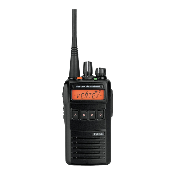
EVX-534
1
2
ABC
D
B
C
4
5
GHI
JKL
7
PQ
8
RS
TUV
?
DEL
0
EVX-534
EVX-539
P
rogrammable
IP57 Submersible (1 m/30 min.)
Available Programmable Function Keys
2-Tone Encode/Decode
5-Tone Encode/Decode
MDC-1200 ® Encode/Decode
Scan
Group Scan
Dual Watch
FM-Scan ( Follow-Me Scan )
TA Scan
Encryption
Privacy ( Basic/Enhanced )
VOX
Talk Around
Emergency
Lone Worker
TX Save Disable
Direct Channel Entry
A
3
Code Up/Down
DEF
B
6
Code Set
ø 1, 3
MNO
C
CXL
9
WX
Speed Dial
YZ
D
OK
#
DTMF Code Set
ID Check
ø 1, 3
EVX-539
Text Message
ARTS
ø 1
TM
F
/F
unctions
ø 1
ø 1
ø 1
ø 1
ø 2
ø 3
ø 1, 3
ø 1
ø 1, 4
ø 2, 3
II
( Auto Range Transpond System )
/ARTS
TM
ø 1: Analog mode
ø 2: Digital mode
ø 3: EVX-534/-539
ø 4: EVX-539 only
eatures
Advertisement
Table of Contents

Related Manuals for Vertex Standard EVX-530 Series


Summary of Contents for Vertex Standard EVX-530 Series
- Page 1 rogrammable unctions eatures IP57 Submersible (1 m/30 min.) Available Programmable Function Keys 2-Tone Encode/Decode ø 1 5-Tone Encode/Decode ø 1 MDC-1200 ® Encode/Decode ø 1 Scan Group Scan Dual Watch FM-Scan ( Follow-Me Scan ) ...
-
Page 2: Table Of Contents
ontents LCD.Icons.&.Indicators. ( EVX-534/-539 ) .....14 Introduction...............1 Intrinsic.Safety.(IS).Information......2 Operation..............15 Warning!.FCC.RF.Exposure.Requirements...3 Preliminary Steps ..........15 Warning!.IC.RSS.General.Requirement....5 Operation Quick Start ........15 Before.You.Begin............7 Automatic Time-Out Timer .......18 Battery Pack Installation and Removal ....7 Advanced.Operation..........19 Battery Charging ..........8 Programmable Key Functions ......19 Low Battery Indication ........9 Description of Operating Functions ....22 Belt Clip Installation and Removal ....10 Lock................43 ARTS™/ARTSII™. -
Page 3: Introduction
512-channel capacity within a maximum 32 groups which can each be programmed with an 8-character Alpha- Numeric Tag. Important channel frequency data is stored in the flash memory, and is easily programmable by a Vertex Standard licensed dealers using a personal computer with Vertex Standard Programming equipment: FIF-12 USB Program- ming Interface, and CT-106 Connection cable with CE142 Software. -
Page 4: Intrinsic.safety.(Is).Information
Substitution of components may impair intrinsic safety. Installation of FNB-V134LIIS-UNI does NOT convert normal EVX-530 into IS version. r To acquire the IS version of the EVX-530 series you much select the Intrinsically Safe battery option at the time of purchase. -
Page 5: Warning!.Fcc.rf.exposure.requirements
! fcc rf e arnIng xposure equIrements This Radio has been tested and complies with the Federal Communications Commission (FCC) RF exposure limits for Occupational Use/Controlled exposure environment. In addition, it complies with the following Standards and Guidelines: r FCC 96-326, Guidelines for Evaluating the Environmental Effects of Radio-Frequency Radiation. r FCC OET Bulletin 65 Edition 97-01 (2001) Supplement C, Evaluating Compliance with FCC Guidelines for Human Exposure to Radio Frequency Electromagnetic Fields. - Page 6 NOT comply with the FCC RF exposure requirements and should be avoided. When operate the radio with the Vertex Standard CLIP-20 belt-clip, make the transmission time as short as possible, to keep the Body Worn configuration.
-
Page 7: Warning!.Ic.rss.general.requirement
NOT comply with the IC RSS General Requirement and should be avoided. When operate the radio with the Vertex Standard CLIP-20 belt-clip, make the transmission time as short as possible, to keep the Body Worn configuration. - Page 8 ! Ic rss g arnIng eneral equIrement rench r Conformément à la réglementation d’Industrie Canada, le présent émetteur radio peut fonctionner avec une antenne d’un type et d’un gain maximal (ou inférieur) approuvé pour l’émetteur par Industrie Canada. Dans le but de réduire les risques de brouillage radioélectrique à...
-
Page 9: Before.you.begin
The IS version of the EVX-530 series is only intrinsically safe with the use of the FNB-V134LIIS-UNI Battery Pack. To acquire the IS version of the EVX-530 series you much select the Intrinsically Safe bat- tery option at the time of purchase. Replacement FNB-V134LIIS-UNI batteries may also be purchased however to be considered IS the radio must have originally been purchased with the IS battery option. -
Page 10: Battery Charging
Intrinsic Safety (IS) is required you must use the FNB-V134LIIS-UNI battery. PA-55 2) Use only the Vertex Standard CD-58 Desktop Charger and the Vertex Standard PA-55 AC Adapter. 3) Do not charge batteries in hazardous locations. 4) To reduce the risk of explosion, recharge the bat- teries outside of hazardous locations. -
Page 11: Low Battery Indication
efore egIn Low Battery Indication 5) Perform the battery charging where the ambient temperature range +41 °F to +104 °F (+5 °C to +40 As the battery discharges during use, the voltage °C). Charge out of this range could cause damage gradually becomes lower. -
Page 12: Belt Clip Installation And Removal
efore egIn Belt Clip Installation and Removal MIC/SP CAP Installation r To install the Belt Clip: align r To remove the Belt Clip: use a Install the MIC/SP cap with the supplied screws. the Belt Clip to the groove of flat head screw driver to press the Battery pack, then press the Belt Clip Tab away from... -
Page 13: Controls.&.Connectors
( eVx-531 ) & c ontrols onnectors VOL ( Volume ) /PWR ( Power ) Knob LED Indicator ( Programmable ) Default settings are: CH ( Channel ) Selector Steady Red: Transmitting in progress ( Analog ) Antenna Jack Steady Blue: Transmitting in progress ( Digital ) TOP SEL ( Top Select ) Key Blinking Green: Busy Channel Steady Green:... - Page 14 ( eVx-534 ) & c ontrols onnectors VOL ( Volume ) /PWR ( Power ) Knob LED Indicator ( Programmable ) Default settings are: Transmitting in progress ( Analog ) CH ( Channel ) Selector Steady Red: Steady Blue: Transmitting in progress ( Digital ) Blinking Green: Busy Channel Antenna Jack Steady Green: Tone Squelch in defeated condition TOP SEL ( Top Select ) Key LCD ( Liquid Crystal Display ) 4-Button Programmable Key...
- Page 15 ( eVx-539 ) & c ontrols onnectors VOL ( Volume ) /PWR ( Power ) Knob LED Indicator ( Programmable ) Default settings are: Transmitting in progress ( Analog ) CH ( Channel ) Selector Steady Red: Steady Blue: Transmitting in progress ( Digital ) Blinking Green: Busy Channel Antenna Jack Steady Green: Tone Squelch in defeated condition TOP SEL ( Top Select ) Key LCD ( Liquid Crystal Display ) 16-Button DTMF Keypad...
-
Page 16: Lcd.icons.&.Indicators. ( Evx-534/-539 )
( eVx-534 & eVx-539 ) lcd I & I cons ndIcators : “Scan” is enabled “CALL” Indicator : “Priority Scan” is activated Receiver Monitor “Dual Watch” is activated “Talk-Around” is enabled “Audio Compander” is activated “5-tone Status Call” or “Digital Text Message” is received Low Transmit Power Mode “On” Battery Icon Option SW (Key Function) or “Lone Worker” is activated Priority-2 Channel Group Number “Privacy” or “Encryption” is activated “Group Scan” is enabled RSSI Indicator (four steps) 8-character Alpha-numeric Display “VOX” is activated attery... -
Page 17: Operation
LCD. until you are familiar with the basic operation of The radio announces the the EVX-530 series. Refer to next page for more channel number, if the Channel Announcement information about Speaker/Microphone usage. Feature is enabled via the PC Programming Soft- IMPORTANT NOTE ware. - Page 18 Channel Group is selected by channel and make sure it the CH Selector knob. For further details, contact is clear. your Vertex Standard dealer. Press and hold the PTT r Rotate the VOL/PWR switch. Speak into the...
- Page 19 peratIon r P r e s s t h e ( O r a n g e ) r If a Speaker/Microphone TOP SEL key, SIDE- is available, remove the 2 b u t t o n , o r E V X - plastic cap and its two 534/-539 front panel’s mounting screws from...
-
Page 20: Automatic Time-Out Timer
peratIon Automatic Time-Out Timer r If the BCLO (Busy Channel Lockout) feature has been programmed on an analog channel, the If the selected channel has been programmed for au- radio will not transmit when a carrier is present. tomatic time-out, you must limit the length of each Instead, the radio will generate short beep three transmission. -
Page 21: Advanced.operation
For features that are available in both “Analog” and These PF keys can be customized, via programming “Digital” modes, no icon is shown. by your Vertex Standard dealer, to meet your commu- For future reference, check the box next to each func- nications/network requirements. - Page 22 dvAnced perAtiOn rOgrAmmAble ress ress And unctiOn [ A ] [ B ] [ C ] [ D ] [ Ü ] [ # ] TOP SEL SIDE-1 SIDE-2 None Monitor Monitor -Momentarily- /--- /--- /--- /--- /--- /--- /--- /--- /--- Lamp...
- Page 23 dVanced peratIon rogrammaBle ress ress and unctIon [ A ] [ B ] [ C ] [ D ] [ Ü ] [ # ] TOP SEL SIDE-1 SIDE-2 Group Scan Dual Watch FM Scan Scan Set Group Scan Set TA Scan Talk Around Reset Call 1 Call 2 Call 3 Call 4 ø1 Call 5...
-
Page 24: Description Of Operating Functions
dVanced peratIon Description of Operating Functions onItor oWer Press, (or press and hold), the assigned PF key to Press, (or press and hold), the assigned PF key to set cancel any signaling features; the LED indicator the radio’s transmitter to “Low Power” mode, thus will glow with a pre-defined color (Factory default: extending battery life. - Page 25 dVanced peratIon ( eVx-534 & eVx-539 ) ( eVx-534 & eVx-539 ) rIVacy You can change the privacy settings to best meet your Press, (or press and hold), the assigned PF key to ac- security requirements using this function: tivate the “User Set (Menu)” mode. See page 43 for r Press, (or press and hold), the assigned PF key.
- Page 26 dVanced peratIon r Press the SIDE-1/SIDE-2 buttons (or [ A ] / [ B ] af m ( eVx-534 & eVx-539 ) InImum olume keys) to select the desired squelch level. Available Press, (or press and hold), the assigned PF key, the selections are “SQLLV OP (Open)”, “SQLLV display indicates “AFATT ON”...
- Page 27 You can manually adjust the VOX Gain using this mergency function: The EVX-530 series includes an “Emergency” fea- r Press, (or press and hold), the assigned PF key. A ture in either analog or digital modes, which may be tone will sound, and the current VOX Gain level useful for alerting another party monitoring on the will appear on the display.
- Page 28 “- EMG -” indication will be indicated on the dis- The EVX-531 has two Channel Groups (Group 1 and play. For further details contact your Vertex Standard Group 2). dealer. Press (or press and hold) the assigned Programmable...
- Page 29 PF key, the display indicates “PRI2 EN” briefly, and call the pre-programmed Priority Channel (Priority-1) enabling the priority channel 2 of the group. by your Vertex Standard dealer directly. The “P1” ch 1 ch 4 ( eVx-534 & eVx-539 ) Irect will appear at the upper right corner on the display.
- Page 30 “User Programmed” channel (“Select Channel”) the presence of a signal, and will stop on a channel The channel which defined in the CH Selector if a signal is present. EVX-530 series can scan both knob. digital and analog frequency programmed channels roup simultaneously.
- Page 31 dVanced peratIon the channel which was chosen when pressed the PF In the EVX-534/-539, when the Dual Watch feature key. is activated, the “DW” icon will be indicated on the display. In the EVX-534/-539, when the Group Scan is ac- tivated, the display indicates “GRP SCAN”...
- Page 32 You may wish to have the Scanner pass through more quency every few seconds (interval programmed by than one Group during the scanning process (normally, your Vertex Standard dealer). scanning is performed within the current group only). Note: The TA Scan feature does not activate on the To include the current Group in the scanning loop, Simplex Channel.
- Page 33 dVanced peratIon ( ta ) ( eVx-531 ) round Press, (or press and hold), the assigned PF key to ( eVx-534 & eVx-539 ) activate the Talk Around feature when you are op- Press, (or press and hold), the assigned PF key to erating on duplex channel systems (separate receive send a pre-programmed call signal of the 2-Tone, and transmit frequencies, utilizing a “repeater”...
- Page 34 After entering all DTMF digits, press the PTT peed Your Vertex Standard dealer may have pre-pro- switch to transmit the DTMF code. grammed Auto-Dial telephone number memories into ( eVx-531 ) your radio. Press, (or press and hold), the assigned PF key to To dial a number: send a 2-tone/5-tone sequential tone.
- Page 35 dVanced peratIon When using the MDC1200 System find the “New List” and “Manual” category at the This feature, if enabled, Press, (or press and hold), last of the indication loop. Describes these two the assigned PF key to send an MDC1200 code. functions later.
- Page 36 dVanced peratIon LIST ”, “RADIO CK”, “RADIOMON”, “RE- 539. However, you can not edit the “Tag Name” ø VIVE” and “STUN” (ø : EVX-539 only). of the Contact Alias which determined by the Press the [ D ] key to accept the selected function. CE142 Programming Software.
- Page 37 dVanced peratIon ALT SEL: You may change the alert tone which mand to the designated radio. If the designated assigned to the selected Contact Alias. radio is alive, the designated radio transmits the Press the [ D ] key, then press the SIDE-1/SIDE- ACK command, and then your radio’s display 2 buttons (or [ A ] / [ B ] keys) to select the desired indicates “ACK RECV”.
- Page 38 dVanced peratIon ing the [ Ý ] key, or insert the space character by RECV”. If your radio’s display indicates “NO pressing the [ # ] key. ACK”, the revive command did not succeed. r Press the [ D ] key again, the display indicates STUN: You may stun the designated radio forc- “ALT SEL”...
- Page 39 dVanced peratIon ( eVx-534 & eVx-539 ) ( eVx-534 & eVx-539 ) tatus You can change the 5-tone status code using this Press, (or press and hold), the assigned PF key to function: toggle the Duty function of the 2-tone, 5-tone, or r Press, (or press and hold), the assigned PF key to MDC1200 “On”...
- Page 40 dVanced peratIon r Press the [ C ] key to resume normal display. r Press the SIDE-1/SIDE-2 buttons to select the logged ID of the DTMF Signaling or 5-tone Sig- ( eVx-534 & eVx-539 ) essage naling. You may receive/send the message from/to other radio. r Press the [ B ] key to toggle the display between r Press, (or press and hold), the assigned PF key to the “ID Code display”...
- Page 41 dVanced peratIon Delete (All messages) at the upper right corner of the display. You may Press the [ A ] / [ B ] keys to select the “ALL DEL” find the “ALL DEL” menu which is located at the last message loop.
- Page 42 dVanced peratIon Press the [ D ] key, then press the [ A ] / [ B ] keys (or or “SAVE” menu depending on your purpose, and move to each step as follow. SIDE-1/SIDE-2 buttons) to select the “SEND” menu.
- Page 43 dVanced peratIon Press the [ D ] key again, then edit the message us- ptIon WItch ing the [ 0 ] - [ 9 ] ] key (for select the character) and Activates the optional accessory while pressing the [ A ] / [ B ] key (for select the digit).
- Page 44 dVanced peratIon In the EVX-534/-539, when the Transmit Battery Saver is “on” and “off”, the display indicates “TX SA ON” and “TX SAOFF” briefly. Press (or press and hold) the assigned PF key to lock the CH Selector knob, Programmable keys, and PTT switch.
-
Page 45: Lock
locK arts ange ranspond ystem In order to prevent accidental channel change or This system is designed to inform you when you and inadvertent transmission, various aspects of the another ARTS -equipped station are within commu- CH Selector knob, Programmable keys, and PTT nication range. - Page 46 The EVX-534/-539 includes a “User Set” (Menu) Mode which allows the user to define or configure various set- tings, such as Squelch, Key lockout configuration, etc. To activate the “User Set” (Menu) Mode: r Press the PF key assigned to the “SET” function r Repeat previous step to adjust other Set Mode to enter the “User Set”...
-
Page 47: User.set.mode
escrIptIon VaIlaBle alues SQL OP ( Open ) , Sets the Squelch level. SQL TH ( Threshold ) , This Set Mode Item is appeared on the Analog channel only. SQL NM ( Normal ) , SQL TI ( Tight ) Beep Enables/Disables the Key Beeper. BEEP ON, BEEP OFF Bell Enables/Disables the Bell function (Alert tone activated by incoming signaling). BELL ON, BELL OFF Light Enables/Disables the back light of the display and keypad. LIGHT ON, LIGHT OFF KEY FRE ( Free ) , KEY LCK ( Lock ) Enables/Disables the Key Lock function. -
Page 48: Optional.accessories
Belt Clip CLIP-20 IMPORTANT NOTE If any of the IS Exempt Accessories are used with the IS version of the EVX-530 series, the radio is no longer considered intrinsically safe and must not be used in hazardous loca- tions. EVX-530 S... - Page 49 CT-27 Radio to Radio Cloning Cable Availability of accessories may vary; some accessories are supplied standard per local requirements, others may be unavailable in some regions. Check with your Vertex Standard Dealer for changes to this list. EVX-530 S EriES...
-
Page 50: Warranty.policy
Vertex Standard warrants, to the original purchaser only, its Vertex Standard manufactured communications prod- ucts against defects in materials and workmanship under normal use and service for a given period of time from the date of purchase. Limited Warranty Details: North America customers (USA and Canada): http://www.vertexstandard.com/lmr/warranty-terms.aspx... - Page 51 The AMBE+2TM voice coding Technology embodied in this product is protected by intellectual property rights including patent rights, copyrights and trade secrets of Digital Voice Systems, Inc. This voice coding Technology is licensed solely for use within this Communications Equipment. The user of this Technology is explicitly prohibited from attempting to decompile, reverse engineer, or disassemble the Object Code, or in any other way convert the Object Code into a human-readable form. U.S. Pat. Nos. #5,870,405, #5,826,222, #5,754,974, #5,701,390, #5,715,365, #5,649,050, #5,630,011, #5,581,656, #5,517,511, #5,491,772, #5,247,579, #5,226,084 and #5,195,166. isposal your lEctronic lEctric quipmEnt Products with the symbol (crossed-out wheeled bin) cannot be disposed as household waste. Electronic and Electric Equipment should be recycled at a facility capable of handling these items and their waste by products. In EU countries, please contact your local equipment supplier representative or service center for informa- tion about the waste collection system in your country. Part 15.21: Changes or modifications to this device not expressly approved by Vertex Standard could void the user’s authorization to operate this device.
- Page 52 Vertex Standard LMR, Inc. Copyright 2014 Vertex Standard LMR, Inc. All rights reserved. No portion of this manual may be reproduced without the permission of Vertex Standard LMR, Inc.
Need help?
Do you have a question about the EVX-530 Series and is the answer not in the manual?
Questions and answers