
Related Manuals for Eneo MAM-5ME1001MTA


Summary of Contents for Eneo MAM-5ME1001MTA
- Page 1 Quick Installation Guide Multisignal Converter, HD- TVI, AHD, 960H to IP, H.264, 1920x1080, 12VDC MAM-5ME1001MTA...
-
Page 2: Table Of Contents
Table of Contents Components........................5 Installation ........................6 Installation ...................................6 Installing Encoder ................................6 Connectors ..................................7 Connections ..................................7 Connecting the Network ............................7 Connecting the Power ..............................7 Connecting RS485 ..............................8 Network Connection & IP Assignment .........................8 Resetting to the factory default settings......................9 Further information ..............................10... - Page 3 Safety instructions General safety instructions • Before switching on and operating the system, first read this safety advice and the operating instructions. • Keep the operating instructions in a safe place for later use. • Installation, commissioning and maintenance of the system may only be carried out by authorised individuals and in accordance with the installation instructions - ensuring that all applicable standards and guidelines are followed.
- Page 4 Class A device note This is a Class A device. This device can cause malfunctions in the living area; in such an event, the operator may need to take appropriate measures to compensate for these. WEEE (Waste Electronical & Electronic Equipment) Correct Disposal of This Product (Applicable in the European Union and other European countries with separate collection systems).
-
Page 5: Components
Components This system comes with the following components; • HD encoder • Installation Guide/CD • Mounting bracket • Accessory Kit NOTE: Adapter for 12 VDC is not supplied. -
Page 6: Installation
Installation Installation For the operation of the HD encoder, it is necessary to connect a network cable for data transmission, power connection from supplied power adapter. For its fixation on different locations, please consult with an installer. Installing Encoder Mount screw Mount screw Mount bracket Encoder... -
Page 7: Connectors
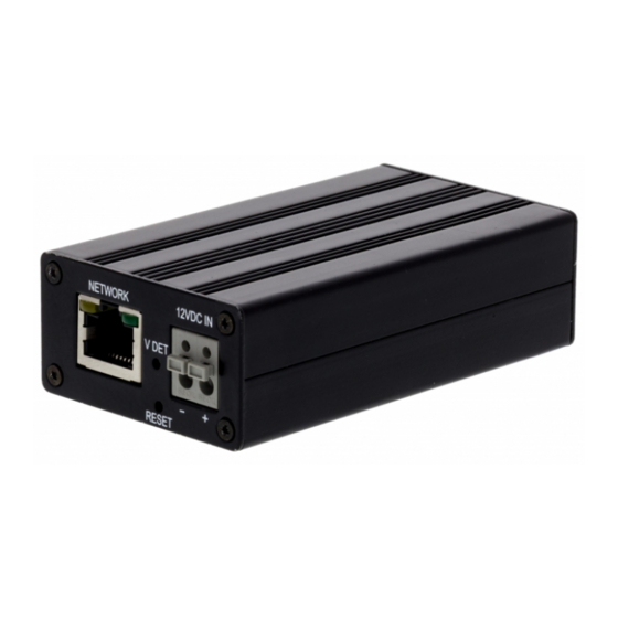
Connectors Connector Description RJ-45 Ethernet, RJ-45 port compatible with 10/100Mbps modular jack 2-pin terminal 12 VDC input BNC camera video input 2-pin terminal 12 VDC output for BNC camera 3-pin terminal RS485 Connections Connecting the Network Connect a standard RJ-45 cable to the network port of the encoder. Generally a crossover cable is used for directly connection to PC, while a direct cable is used for connection to a hub. -
Page 8: Connecting Rs485
The eneo Site Manager (downloadable from www.eneo-security.com) is used to locate all eneo network cameras in a local network. The tool does not need to be installed with a setup program. The program exe-file can be started with a simple double click to use the program. -
Page 9: Resetting To The Factory Default Settings
Select the „Set IP Address [dhcp / static]“ option to open a window for setting the camer- as IP properties. When you are done click the „OK“ button to update the camera settings. For further information, please refer to the eneo Site Manager Quick Start Guide. Resetting to the factory default settings To reset the encoder to the original factory settings, go to the Setup >... -
Page 10: Further Information
(Default IP 192.168.1.10) Further information Make sure to always upgrade to the latest firmware version available from the eneo web- site at www.eneo-security.com to receive the latest functionality for your product. The manual, and other software tools are available on the eneo website at www.eneo-se- curity.com or on the included CD. - Page 12 VIDEOR E. Hartig GmbH Exclusive distribution through specialised trade channels only. VIDEOR E. Hartig GmbH Carl-Zeiss-Straße 8 63322 Rödermark/Germany Tel. +49 (0) 6074 / 888-0 Technical changes reserved Fax +49 (0) 6074 / 888-100 www.videor.com...
Need help?
Do you have a question about the MAM-5ME1001MTA and is the answer not in the manual?
Questions and answers