Table of Contents
Advertisement
Quick Links
Advertisement
Table of Contents

Related Manuals for Eneo TAM-4MM1001M0A


Summary of Contents for Eneo TAM-4MM1001M0A
- Page 1 User Manual HD-TVI Converter to HDMI/VGA/ CVBS, Indoor TAM-4MM1001M0A...
-
Page 2: Table Of Contents
Table of content Parts supplied .......................4 Panel View ........................5 LED Indication ...................................5 Switch and Button Functions ..................7 DIP Switch 1: LOOPOUT / CVBS OUT Function Selection ................7 DIP Switch 2 : INPUT/OUTPUT Mode Selection ....................8 DIP Switch 3: PIP Mode ............................8 DIP Switch 4: PIP Dimension Setting ........................9 Restore Factory Default ..............................9 Installation ........................10... - Page 3 Safety instructions General safety instructions • Before switching on and operating the system, first read this safety advice and the operating instructions. • Keep the operating instructions in a safe place for later use. • Installation, commissioning and maintenance of the system may only be carried out by authorised individuals and in accordance with the installation instructions - ensuring that all applicable standards and guidelines are followed.
-
Page 4: Parts Supplied
Graphical symbols Please pay attention to the safety instructions, and carefully read through this instruction guide before initial operation. Important points of warning are marked with a caution symbol. Important points of advice are marked with a notice symbol. Parts supplied •... -
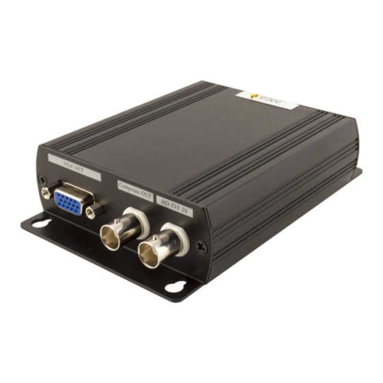
Page 5: Panel View
Panel View DC 12 V DC 12V power terminal HDMI OUT HDMI output interface VGA OUT VGA output interface ➀ IN First source input interface ② IN/OUT Multiple function source input/output interface LED Indication DC Jack LED: Green P Power ON Blue S Input 1 signal received Red H... - Page 6 ② IN/OUT Connector LED (BNC): Green L Under LOOPOUT mode Blue S Input 2 signal received Red C CVBS OUT mode...
-
Page 7: Switch And Button Functions
Switch and Button Functions DIP Switch 1: LOOPOUT / CVBS OUT Function Selection DIP Switch 1 ⇑ (LOOPOUT) ② IN/OUT connector setting as LOOPOUT mode Button for resolution switching, press ◄ button to decrease the resolution, press ► button to increase output resolution. Resolution for switch sequence will be follow as below: 480p ➔... -
Page 8: Dip Switch 2 : Input/Output Mode Selection
DIP Switch 2 : INPUT/OUTPUT Mode Selection DIP Switch 2 ⇑ (Output Mode) ② IN/OUT connector setting as output mode, ② IN/OUT connector function followed by DIP Switch 1 selection. DIP Switch 2 ⇓ (Input Mode) ② IN/OUT connector setting as input mode, ② IN/OUT connector function as input 2, DIP Switch 1 setting will be ignored. -
Page 9: Dip Switch 4: Pip Dimension Setting
Button as PIP sub-screen display position, press ◄ Counter-Clockwise to switch, press ► Clockwise switch When press two buttons together, two inputs can be switched between the main picture and sub picture. DIP Switch 4: PIP Dimension Setting DIP Switch 4 ⇓ (Adjust PIP Dimension) This function can only be activated on DIP Switch 2 and DIP Switch 3 both at ⇓... -
Page 10: Installation
Installation HD-TVI Loopout Mode 3 outputs: HDMI, VGA, HD-TVI loop output as a distributor. CVBS Output Mode 3 outputs: HDMI, VGA, CVBS could be display simultaneously. -
Page 11: Hd-Tvi Input Mode
HD-TVI Input Mode Allow HD-TVI camera 2 inputs with 2 outputs: HDMI, VGA as a switcher. - Page 12 VIDEOR E. Hartig GmbH Exclusive distribution through specialised trade channels only. VIDEOR E. Hartig GmbH Carl-Zeiss-Straße 8 63322 Rödermark/Germany Tel. +49 (0) 6074 / 888-0 Technical changes reserved Fax +49 (0) 6074 / 888-100 www.videor.com...
Need help?
Do you have a question about the TAM-4MM1001M0A and is the answer not in the manual?
Questions and answers