Table of Contents
Advertisement
Quick Links
Advertisement
Table of Contents

Related Manuals for Extech Instruments 400790A


Summary of Contents for Extech Instruments 400790A
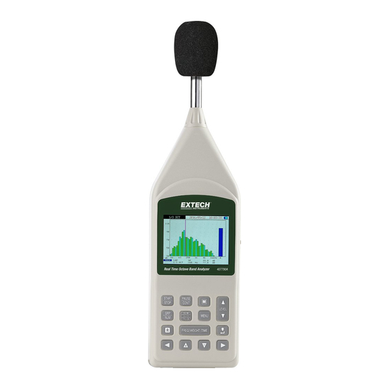
- Page 1 User Manual Real Time Octave Band Analyzer Model 407790A ...
-
Page 2: Table Of Contents
Table of Contents INTRODUCTION ....................3 1.1 Instrument Care .................... 4 1.2 Features ......................5 DESCRIPTIONS ....................6 2.1 Meter Description ..................6 2.2 Operation Buttons ..................7 2.3 Display Screen ....................9 ... -
Page 3: Introduction
1. Introduction Congratulations on your purchase of the Extech 407790A Real Time Octave Band Analyzer. This auto ranging Type 2 integrating sound level meter features 1/1 and 1/3 Octave Band real‐time noise analyses. The 407790A offers five measurement parameters: SPL (Sound Pressure Level), Leq (Equivalent Continuous Sound Pressure Level), SEL (Sound Exposure Level), Lmax (Maximum Sound Pressure Level), and Lmin ... -
Page 4: Instrument Care
1.1 Instrument Care Do not attempt to remove the mesh cover from the microphone as this will cause damage and affect the accuracy of the instrument. Protect the instrument from impact. Do not drop it or subject it to rough handling. Transport it in the supplied carrying case. Protect the instrument from water, dust, extreme temperatures, high humidity and direct sunlight during storage and use. Protect the instrument from air with high salt or sulfur content, gases and stored chemicals, as this may damage the delicate microphone and sensitive electronics. Always switch the instrument off after use. Remove the batteries from the instrument if it is not to be used for a long period of time. Do not leave exhausted batteries in the instrument, as they may leak and cause damage. Clean the instrument only by wiping it with a soft, dry cloth or, when necessary, with a cloth lightly moistened with water. Do not use solvents, abrasives, alcohol or cleaning agents 407790A-en-US_v2.0 8/16... -
Page 5: Features
1.2 Features The Sound Level Meter complies with the requirements of IEC 61672‐1:2003 standard for a Class 2 instrument. See specifications section for more applicable standards that apply to this meter. 1/1 octave band analysis from 31.5Hz to 8kHz 1/3 octave band analysis from 25Hz to 10kHZ Can perform 1/1 and 1/3 octave band analysis simultaneously 4GB Micro SD card USB interface Datalogging function AC/DC signal output available for level and graphic recorder Comparator output function External trigger input function Real time clock with calendar Main channel (sound meter, analyzer mode) Sub Channel (sound level meter mode) The 407790A allows the following quantity measurements. Simultaneous measurements of all items with selected time weighting and frequency characteristics. Sound level Lp Equivalent continuous sound Leg Sound exposure level ... -
Page 6: Descriptions
2. Descriptions 2.1 Meter Description Refer to the diagram below for the following descriptions. Windscreen Trig IN jack Microphone 10. Micro SD card slot Display 11. Power switch Operation keys 12. Hand strap 6VDC adapter jack 13. USB port DC analog output jack 14. Battery compartment AC analog output jack Tripod mounting screw Comparator output jack FAST 65.2 dB 31.5 [ 1 / 3 OCT ] 01 / 06 / 19 14:26:39 SOUND ANALYZER 1/1 &... -
Page 7: Operation Buttons
2.2 Operation Buttons START/STOP button Press to start or stop for recording the sound pressure measurement. PAUSE/CONT button Press to temporarily pause ( ) a measurement) or resume () measurement. M button Press to scroll through and select different processing modes. LEVEL Press to select the level range for measurement. The following five settings are available. 20 to 90 dB, 20 to 100 dB, 20 to 110 dB, 30 to 120 dB, 40 to 130 dB. GRP/ NUM button Press to switch between graph and numeric display for Octave measurements. SLM 1/1 1/3 button Press to switch to select the sound level meter display and analysis screen. (SLM, 1/1, 1/3, 1/1&1/3) MENU Press to enter menu screen to setup various menu parameters. Press again to close the menu. R button Start or stop the auto Record process or press to manually store the measurement data into memory. 407790A-en-US_v2.0 8/16... - Page 8 / Press to move the octave frequency band marker during frequency analysis. / Press to select and set items in various menu screens. Holding the buttons down will cause faster scrolling. FREQ WEIGHT TIME button The FREQ WEIGHT selects the frequency weighting for the main channel. “A” weighting (A), “C” weighting (C), and flat frequency response (Z). The TIME WEIGHT selects the time weighting function for the main channel. (F, S, 10ms, I) Fast: 125ms; Slow: 1000ms; 10ms; Impulse: 35ms Note: The frequency and time weighting for the sub channel can be selected by accessing the menu screen. button (Backlight/Enter) Backlight powers on the display backlight. Press the button again to turn backlight off. When automatic Backlight Off function is selected from the menu screen, the backlight will turn itself off automatically after the preset time. Enter button will finalize a setting of an item in a menu or any other setting. 407790A-en-US_v2.0 8/16...
-
Page 9: Display Screen
2.3 Display Screen Measurement in progress symbol Memory Trigger mode Store mode Mode of analysis USB link status Elapsed time Address Bar graph Level range Overload indication Underrange indication Sub channel level display Main channel Frequency weighting Sub channel Ti me weighting Time weighting Frequency weighting Main channel level... - Page 10 8. Address: Displays current number of data surveys stored in memory. 9. Bar graph: Displays the sound level as a bar graph. (The display is updated every 100ms) 10. Level range: Displays the upper and lower limit of the bar graph. Can be changed with the LEVEL button. 11. Under‐range indication: When a signal is under‐range the UN symbol will appear on the screen. Use the LEVEL button to decrease the level range setting. If processed data is under‐range the UN indication will remain on the screen until the next processing measurement is started. 12. Overload indication: When a signal overload is detected, the screen will display OV for at least 1 second. Use the LEVEL button to increase the level range setting. If processed data is over range the OV indication will remain on the screen until the next processing measurement is started. 13. Main channel frequency weighting: Indicates the main channel frequency characteristic. A: A‐weighting, C: C‐weighting, Z: Z‐weighting (flat response) 14. Main channel time weighting: Indicates the main channel time weighting characteristic. F: Fast (125ms), S: Slow (1000ms), τ: (10ms), I: Impulse (35ms) 15. Main channel level display: Displays the measured sound level in the main channel. (The display is updated every second). 16. Sub channel frequency weighting: Indicates the sub channel frequency weighting characteristic. A: A‐weighting, C: C‐weighting, Z: Z‐weighting (Flat response). The sub channel frequency weighting can be set from the menu screen. 17. Sub channel time weighting: Indicates the sub channel time weighting characteristic. F: Fast (125ms), S: Slow (1000ms), τ: (10ms), I: Impulse (35ms) 18. Sub channel level display: Shows the measured sound level in the sub channel. (The display is updated every second) 19. Power status: When operating the meter on battery power the yellow segments will decrease as the battery power drains. When the segment starts to flash, replace batteries. Yellow Yellow Yellow Yellow...
-
Page 11: Analysis Screen
2.4 Analysis screen An example for the 1/1 & 1/3 OCT analysis screen is shown below. Use the and buttons to move the cursor to the target frequency band. 1/1 and 1/3 analysis screen 407790A-en-US_v2.0 8/16... -
Page 12: Numeric Display Screen
2.5 Numeric Display screen Example for 1/1 OCT, 1/3 OCT, and 1/1 & 1/3 OCT analysis screen are shown below. Use the and buttons to view a frequency that is not displayed. 407790A-en-US_v2.0 8/16... -
Page 13: Measurement Preparation And Setup
3. Measurement Preparation and Setup 1. Battery installation: Remove the rear battery cover as shown below and insert (4) 1.5V ‘C’ size alkaline batteries. Take care to observe battery polarity. Replace the battery cover. 2. Battery replacement: When the battery voltage drops below operating voltage, battery symbol flashes on the display. 3. AC adaptor connection: Insert the adaptor in the DC 6V jack on the side panel. When the AC adapter is connected, the meter will be powered from the adapter even if batteries are installed. Notes: To prevent the risk of damage, use only the factory supplied AC adapter. To prevent the risk of battery leakage, remove the batteries from the meter when the meter is not in use. 3.1 Setting the Date and Time Date and time information is stored with each record saved. Set the date and time as follows: 1. Press power switch ON and wait until the measurement screen appears. 2. Press the MENU button. The menu list screen will display. 3. Press the / button to select “D) Date setting (Y/M/D)” and then press the enter button. 4. Press the / button to set the value. Press button to confirm. 407790A-en-US_v2.0 8/16... - Page 14 5. Continue pressing the above buttons to scroll through and set each option for date and time. The meter will continue to scroll through setup for date Y/M/D and then the time settings h/m/s. 6. When the settings are correct, press the button to exit the setting mode. The clock will start running with the new settings. 7. Press MENU button to return to the measurement screen. Note: The clock has an error of about 1 minute per month. Before taking measurement, be sure to check and set the time if required. Date Time 407790A-en-US_v2.0 8/16...
-
Page 15: Sd Memory Card
3.2 SD Memory Card Measurement data can be stored on a removable SD memory card for later use. Note: Power OFF the meter before inserting or removing the memory card. Use only a 4GB micro SD card. Removing SD card or powering the meter off while data is storing to the card can cause internal data to be destroyed. Insert the card taking care to observe the correct orientation. Push the card in carefully, until it is properly sealed. To remove, push the card. The SD card with pop out and can be removed. 3.3 Setting the Backlight Auto Off time 1. Press the to turn the backlight on or off. 2. Press the MENU key to bring up the menu list screen. 3. Use the / key to select “Backlight Auto Off” then press the key. 4. Use the / key to select the automatic turn off time then press the key. Options are: 30 seconds, 1 minute, 3 minutes or OFF (without automatic turn ‐ off function). 5. Press MENU key to return to the measurement screen. To turn the backlight off before the automatic turn ‐ off time, press the key. 407790A-en-US_v2.0 8/16... -
Page 16: Sub Channel Settings
3.4 Sub Channel Settings To access the sub menu setting press the following buttons. 1. Press the MENU button to enter the menu list screen. 2. Use the / buttons to select “G). Sub Time Weight” then press button. 3. Use the / button to select the desired time weighting F, S, τ (10ms) or I (Impulse 35ms), then press button. 4. Press the / buttons to select “H). Sub Freq Weight” then press button. 5. Press the / buttons to select the desired frequency weighting A, C or Z, then press button. 6. Press MENU button to return to the measurement screen. Note: There is no frequency analysis function for the sub channel. Only the all ‐ pass value is measured. 407790A-en-US_v2.0 8/16... -
Page 17: Selecting The Lmax/Lmin Type
3.5 Selecting the Lmax/Lmin type Band ‐ (Band maximum/band minimum): The analysis result applies to the point where the level for each frequency band was maximum or minimum within the sampling period. AP ‐ (All‐pass maximum/all‐pass minimum): The analysis result applies to the sub channel all‐pass and band‐pass level values taken at the point where the all‐pass level in the main channel was maximum/minimum within the sampling period. AP (S) ‐ (All‐pass maximum/all‐pass minimum): The analysis result applies to the band‐pass level values (excluding the sub channel all‐pass levels) taken at the point where the all‐pass level in the main channel was maximum/minimum within the sampling period. The sub channel all‐pass level is taken at the maximum/minimum point within the sampling period, independently of the main channel level. 1. Press the MENU button to enter the menu list screen. buttons to select “I) . Lmax/Lmin Type” then press button. 2. Use the / 3. Use the / buttons to select the desired Band, AP or AP (S) type then press button. 4. Press MENU button to return to the measurement screen. This setting is effective in SLM mode and Octave band analyzer mode. 407790A-en-US_v2.0 8/16... -
Page 18: Comparator Output Operation
3.6 Comparator Output Operation The comparator output is an open collector output that can be used to control external equipment. 1. Press the MENU button to enter the menu list screen. 2. Use the / buttons to select “J). Comparator” then press button to display the ON/OFF setting. 3. Press the / buttons to select “ON” then press button. 4. Press the / buttons again to select “1). Comparator Level”. Set the desired level then press button. (Setting range 25 to 130dB, 1 ‐ dB steps) 5. Follow the above steps to select “2). Comparator Band”. Set the band to desired level then press button. (MAIN AP/31.5Hz/63Hz/…8kHz or 1/3 octave bands). 6. Press the MENU button to return to the measurement screen. 407790A-en-US_v2.0 8/16... - Page 19 407790A-en-US_v2.0 8/16...
- Page 20 Comparator output: In the SLM mode, only the AP is selected as comparator band. In the 1/1 OCT mode, only the AP or 1/1 octave band is selected as comparator band. Comparator output: Open‐ collector output; band‐level determination; Max. applied voltage: 24VDC; Max. drive current: 50mADC 1. Comparator signal output continues for 0.5 seconds after the signal crosses the threshold level 2. Comparator Level 3. Time 407790A-en-US_v2.0 8/16...
-
Page 21: Trigger Mode Setup And Operation
3.7 Trigger Mode Setup and Operation A measurement can be initiated by one of three triggers: time trigger (time‐controlled triggering), level trigger (sound level controlled triggering), and external trigger (triggering by an external signal). Level trigger 1: Measurement starts when the trigger level is exceeded and ends after the measurement time. The trigger level is valid at any time. Setting items: Trigger Slope Type: +, ‐ Trigger Level: 25 to 130dB, 1‐dB steps. Trigger Band: MAIN AP/31.5Hz/63Hz/125Hz….8kHz (1/3 octave bands) Level trigger 2: Single measurement is made when trigger level is exceeded. The trigger level is valid at any time. Setting items: Trigger Level: 25 to 130dB, 1‐dB steps. Trigger Band: MAIN AP/31.5Hz/63Hz/125Hz…8kHz (1/3 octave bands). Time trigger: This is a reoccurring trigger timer that starts a measurement after a trigger timer. The measurement ends after the measurement time. The trigger timer is valid at all times. Setting items: Trigger Time: h:m:s External trigger: A Measurement starts at falling edge of a logic‐level (0 to 5V logic) signal at the external trigger input. A Pulse width of 1ms or more is required. The external trigger is valid at all times Trigger Operation ‐ example Sound Level Time Slope + Trigger Slope ‐ Trigger Trigger Level 407790A-en-US_v2.0 8/16... -
Page 22: Trigger Setup
3.7.1 Trigger Setup Chose trigger operation [off, Level 1, Level 2, External, or Time]. Set the Trigger Band: AP or Octave band frequency For Level 1 and 2: chose the Trigger level in dB. External Trigger, chose slope (+ or ‐) 3.7.2 External Trigger Setting ... -
Page 23: Trigger Level Setting
buttons to select “2) . Trigger Band” then press the button. 4. Use the and buttons to set the value to AP then press the button. 5. Use the buttons to select “3) . Trigger Time” then press the button. 6. - Page 24 buttons to select the desired trigger band then press the button. 7. Use the buttons to select “4) . Slope Type” then press the button. 8. Use the buttons to select the desired trigger slope + or Slope‐. Then press the 9.
-
Page 25: Measurements
4.Measurements All processing functions provided by the meter (Leq, SEL, Lmax, Lmin, Ln) are carried out simultaneously. For example, when equivalent continuous sound level measurement is selected, the sound exposure level and percentile level are also determined. 4.1 Sound Level Measurements 1. Press the power button to power on the meter. After the power‐on screen displays the SLM measurement screen will appear. -
Page 26: Sel, Leq, Lmax, Lmin, Ln Measurements
4.2 SEL, Leq, Lmax, Lmin, LN Measurements 1. Power on the meter. After the power‐on screen displays, the SLM measurement screen appears. 2. Use the FREQ WEIGHT TIME button to select the frequency weighting characteristic. For normal sound level measurements, select the “A” setting. When “C” (C‐Weighting) is selected, the equivalent continuous sound pressure level (LCeq) is measured. - Page 27 8. Press the button to exit the measurement time setting. 9. Press MENU button to return to the measurement screen. 10. Press the START/STOP button to start the measurement. Previously measured values will be cleared. While the measurement is in progress, the symbol will flash and the elapsed time will display on the screen.
-
Page 28: Sound Level And Octave Band Analysis Measurement
4.3 Sound Level and Octave Band Analysis Measurement 1. With the power ON wait until the SLM measurement screen appears on the display. 2. Use the SLM 1/1 1/3 button to select the desired 1/1 OCT, 1/3 OCT or 1/1 & 1/3 OCT band or SLM measurement screen. 3. - Page 29 407790A-en-US_v2.0 8/16...
-
Page 30: Sound Band - Leq, Sel, Lmax, Lmin And Ln Analysis Measurement
4.4 Sound Band ‐ Leq, SEL, Lmax, Lmin and LN Analysis Measurement 1. Power on the meter and wait until the SLM measurement screen appears. 2. Use the SLM 1/1 1/3 button to select the desired 1/1 OCT, 1/3 OCT or 1/1 & 1/3 OCT band or SLM measurement screen. 3. Use the FREQ WEIGHT TIME button to select the frequency weighting characteristic. For normal measurements, select the “A”... - Page 31 If the indication “UN” is shown, the processed data include data where the sound level signal caused an under‐range condition. (SEL) Lmax 13. Press the M button to cycle through the Lp Leq L Lmin L05 L10 L50 L90 L95 measured value on the screen. Pressing the GRP/NUM button switches the measurement screen between graph and numeric display.
-
Page 32: Storing Data To Memory
5. Storing Data to Memory The meter can store measurement data in the internal memory or on a micro SD card. There are three different ways of storing data, as listed below. Manual: In this mode, the operator stores the measured sound level data and processed value data into the memory manually. - Page 33 Selecting FLASH will store the data in the internal memory. Selecting SD Card will store the data on the SD CARD. buttons to select “C) . Store Mode” then press the key. 5. Use the buttons to select “MANUAL” then press the key. 6.
- Page 34 407790A-en-US_v2.0 8/16...
-
Page 35: Recalling Manually Stored Data
5.2 Recalling Manually Stored Data 1. Power on the meter. 2. Press the MENU button to enter the menu list screen. buttons to select “M) . Recall” then press the button. 3. Use the 4. Use the buttons to select the store address whose data you want to recall, then press the button. - Page 36 407790A-en-US_v2.0 8/16...
-
Page 37: Erasing Manually Stored Data
5.3 Erasing Manually Stored Data 1. Press the MENU button to enter the menu list screen. buttons to select “L) . Clear Record” then press the button. 2. Use the buttons to select “MANUAL” then press the button. 3. Use the A confirmation message will appear. -
Page 38: Auto 1 Memory Storage
5.4 Auto 1 Memory Storage Memory Store Continuously store the current measured data as 1 set, at preset record interval times. 1. Power on the meter. 2. Press the MENU button to enter the menu list screen. buttons to select “B) . Storage” then press the button. 3. - Page 39 To stop the process earlier, press the START/STOP or the R key. When the store is completed or stopped, the memory block address is incremented by one step. Note: When memory block address 250 is reached, the AFul symbol is displayed and no more data can be stored. ...
- Page 40 407790A-en-US_v2.0 8/16...
-
Page 41: Auto 2 Memory Storage
5.5 Auto 2 Memory Storage Memory Store Continuously store the processed data at a preset measurement integrated time. 1. Power on the meter. 2. Press the MENU button to enter the menu list screen. buttons to select “B) . Storage” then press the button. 3. -
Page 42: Erasing Auto Stored Data
5.6 Erasing Auto Stored Data 1. Press the MENU button to enter the menu list screen. buttons to select “L) . Clear Record” then press the button. 2. Use the buttons to select “Auto” then press the button. 3. Use the A confirmation message appears. -
Page 43: Software Download And Installation
6. Software Download and Installation The 407790A software is available for free download from the WWW.EXTECH.COM web page, located under the Software downloads section. SAVE the 407790A software to your PC. Perform an “Extract All” to unZIP the files. Run ExtechInstaller.exe to install the software. There is no USB driver, as the meter attaches as a Human Interface device. -
Page 44: Sound Pressure Level - Technical Notes
7. Sound Pressure Level ‐ Technical notes 1. The decibel (dB) The range over which the human ear responds to sound pressure (noise) is extremely large; in Pascals (Pa) it is 20 Pa (the threshold of hearing) to 100 Pa (the threshold of pain). The measurement of sound pressure has been made more convenient by the use of the decibel, which is logarithmic. -
Page 45: Calibration
8. Calibration Calibrating the 407790A requires an acoustical calibrator such as the Extech Model 407766 or 407744 that can provide 94.0dB or 114dB at 1kHz. Set the power switch to the OFF position. Press and hold the buttons then turn the power ON until CAL appears on the screen. -
Page 46: Specifications
9. Specifications Applicable Standards: IEC 61672‐1: 2013 Class 2, IEC 61260‐1: 2014 Class 2, ANSI S1.11: 2004 Class 2, ANSI S1.4: 1983 Type 2, ANSI S1.43: 1997 Type 2 Measurement functions: Simultaneous measurement of main channel and sub channel. Frequency weighting and time weighting are set independently for main and sub channel. ... - Page 47 Time weighting: Main channel: Fast (125ms), Slow (1000ms), 10ms, Impulse (35ms) Sub channel: Fast (125ms), Slow (1000ms), 10ms, Impulse (35ms) Measurement level range: A‐weighting: 25 to 130dB C‐weighting: 33 to 130dB Z‐weighting: 38 to 130dB Total meter range: 25dB to 130dB (A‐weighting, 1kHz) Linear operating range: 90dB Level Range: 20 to 90dB, 20 to 100dB, 20 to 110dB, 30 to 120dB, 40 to 130dB Sampling cycle: 20.8 µS (L : 100ms)
- Page 48 Data recall: Allows viewing of the manually stored data. AC output: 1 Vrms at FS (full scale); Output impedance approx. 5kΩ; Load impedance ≥100kΩ DC output: 10mV/dB; Output impedance approx. 5kΩ; Load impedance ≥100kΩ External trigger input: Detection of 0 to 5V logic‐ level signal, falling edge trigger, pulse width 1ms or more USB: Allows connection to a computer as storage device, or use a communication device for unit control via communication commands.
-
Page 49: Warranty
Calibration, Repair, and Customer Care Services FLIR Systems, Inc. offers repair and calibration services for the Extech Instruments products we sell. We offer NIST traceable calibration for most of our products. Contact our Customer Service Department for information on calibration service availability. Annual calibrations should be performed to verify meter performance and accuracy. Technical support and general customer service is also provided, refer to the contact information provided below.
Need help?
Do you have a question about the 400790A and is the answer not in the manual?
Questions and answers