Table of Contents
Advertisement
Quick Links
Gas Analysis
Sample gas cooler
TC-MIDI (+)
Installation and Operation Instructions
Original instructions
BE440016
Bühler Technologies GmbH, Harkortstr. 29, D-40880 Ratingen
07/2022
Tel. +49 (0) 21 02 / 49 89-0, Fax: +49 (0) 21 02 / 49 89-20
E-Mail: analyse@buehler-technologies.com
Internet: www.buehler-technologies.com
Advertisement
Table of Contents

Related Manuals for Bühler technologies ModbusRTU TC-MIDI


Summary of Contents for Bühler technologies ModbusRTU TC-MIDI
- Page 1 Gas Analysis Sample gas cooler TC-MIDI (+) Installation and Operation Instructions Original instructions BE440016 Bühler Technologies GmbH, Harkortstr. 29, D-40880 Ratingen 07/2022 Tel. +49 (0) 21 02 / 49 89-0, Fax: +49 (0) 21 02 / 49 89-20 E-Mail: analyse@buehler-technologies.com Internet: www.buehler-technologies.com...
- Page 2 Bühler Technologies GmbH, Harkortstr. 29, D-40880 Ratingen Tel. +49 (0) 21 02 / 49 89-0, Fax: +49 (0) 21 02 / 49 89-20 Internet: www.buehler-technologies.com E-Mail: analyse@buehler-technologies.com Read this instruction carefully prior to installation and/or use. Pay at- tention particularly to all advises and safety instructions to prevent in- juries.
-
Page 3: Table Of Contents
TC-MIDI (+) Contents Introduction............................................. 3 Intended use ......................................... 3 Overview .......................................... 3 Scope of delivery ........................................ 3 Ordering instructions ...................................... 4 1.4.1 Gas cooler models with one gas path inside the heat exchanger.................. 4 1.4.2 Gas cooler models with two gas paths insides the heat exchanger.................. 5 1.4.3 Gas cooler models with two heat exchangers in series ...................... - Page 4 TC-MIDI (+) 7.12.1 Consumables and accessories ............................... 39 8 Disposal ............................................ 40 9 Appendices............................................. 41 Gas cooler technical data .................................... 41 Technical Data - Options .................................... 43 Flow diagrams........................................ 44 Dimensions (mm)...................................... 45 Performance data...................................... 47 Heat exchanger......................................... 48 9.6.1 Heat exchanger description ................................ 48 9.6.2 Heat exchanger overview................................
-
Page 5: Introduction
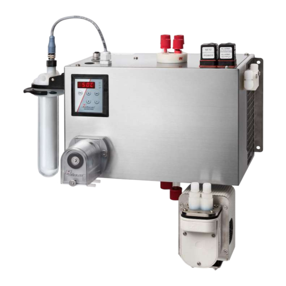
TC-MIDI (+) 1 Introduction 1.1 Intended use This unit is intended for industrial use in gas analysis systems. It's an essential component for conditioning the sample gas to protect the analysis instrument from residual moisture in the sample gas. Please note the specifications in the data sheet on the specific intended use, existing material combinations, as well as pressure and temperature limits. -
Page 6: Ordering Instructions
TC-MIDI (+) 1.4 Ordering instructions 1.4.1 Gas cooler models with one gas path inside the heat exchanger The item number is a code for the configuration of your unit. Please use the following model code: 4496 1 X 0 X X X X X X X X 0 X 0 Product Characteristics Gas cooler types TC-MIDI 6111: Ambient temperature 40 °C... -
Page 7: Gas Cooler Models With Two Gas Paths Insides The Heat Exchanger
TC-MIDI (+) 1.4.2 Gas cooler models with two gas paths insides the heat exchanger The item number is a code for the configuration of your unit. Please use the following model code: 4496 1 X 0 X 2 X X X X X X X 0 X 0 Product Characteristics Gas cooler types TC-MIDI 6111: Ambient temperature 40 °C TC-MIDI 6112: Ambient temperature 60 °C... -
Page 8: Gas Cooler Models With Two Heat Exchangers In Series
TC-MIDI (+) 1.4.3 Gas cooler models with two heat exchangers in series The item number is a code for the configuration of your unit. Please use the following model code: 4496 2 X 0 X X X X X X X X 0 0 0 Product Characteristics Gas cooler types TC-MIDI+ 6121: Ambient temperature 40 °C TC-MIDI+ 6122: Ambient temperature 60 °C... -
Page 9: Safety Instructions
TC-MIDI (+) 2 Safety instructions 2.1 Important advice Operation of the device is only permitted if: – the product is used under the conditions described in the installation- and operation instruction, the intended application according to the type plate and the intended use. In case of unauthorized modifications done by the user Bühler Technolo- gies GmbH can not be held responsible for any damage, –... -
Page 10: General Hazard Warnings
TC-MIDI (+) 2.2 General hazard warnings The equipment must be installed by a professional familiar with the safety requirements and risks. Be sure to observe the safety regulations and generally applicable rules of technology relevant for the installation site. Prevent malfunctions and avoid personal injuries and property damage. -
Page 11: Transport And Storage
TC-MIDI (+) 3 Transport and storage Only transport the product inside the original packaging or a suitable alternative. The equipment must be protected from moisture and heat when not in use. It must be stored in a covered, dry and dust-free room at a temperature of -20 °C to 60 °C (-4 °F to 140 °F). -
Page 12: Installation And Connection
TC-MIDI (+) 4 Installation and connection 4.1 Installation site requirements The unit is only intended for wall-mounted use in enclosed areas. Adequate protection from the weather must be provided when used outdoors. Install the unit leaving enough room below the cooler to discharge the condensate. Leave room above for the gas supply. Be sure to maintain the approved ambient temperature. -
Page 13: Sample Gas Pump Connection Gas Lines (Optional)
TC-MIDI (+) 4.2.4 Sample gas pump connection gas lines (optional) On coolers ordered with attached sample gas pump these are already installed and wired. Add-on parts ordered at the same time are already installed and connected to the sample gas pump. The sample gas pump may be installed both below and next to the cooler. -
Page 14: Electrical Connections
TC-MIDI (+) The gas inputs are marked in red. On glass heat exchangers the correct position of the seal is important when connecting the gas lines (see image). The seal con- sists of a silicone ring with a PTFE sleeve. The PTFE side must face the glass thread. Glass PTFE 4.3 Electrical connections... -
Page 15: Signal Outputs
TC-MIDI (+) Plug connection This device has one EN 175301-803 plug each for the power supply and the signal output. If the lead is connected correctly, these cannot be confused. Therefore please be sure to correctly reassemble the plugs after connecting the wires. Below you will find the pin assignments, with the numbers corresponding to those on the plugs: The supply line cross-sections must be suitable for the rated current. - Page 16 TC-MIDI (+) Description of signal outputs Function/contact type Description Regard- internal changeover con- the following device statuses Contact between 3 and 2 closed (alarm) ing S2) tact: max. can be indicated via two – No mains voltage and/or actual temperature outside 250 VAC/150 VDC, 2 A, switching outputs: the alarm thresholds...
-
Page 17: Operation And Control
TC-MIDI (+) 5 Operation and control NOTICE The device must not be operated beyond its specifications. After switching on the cooler the block temperature will be displayed. The display will flash until the block temperature has reached the preset target value (± adjustable alarm range). The status contact is in the Alarm position. Once the target temperature range has been reached, the temperature will continuously be displayed and the status contact switches over. -
Page 18: Use Of Menu Functions
TC-MIDI (+) 5.3 Use of menu functions Brief description of the operating principle: The unit is operated using 5 keys. Their functions are: Button Section Functions Display – Switches from the measurement display to the main menu Menu – Selects the menu item displayed Enter –... -
Page 19: Overview Of The Menu Items
TC-MIDI (+) 5.3.2 Overview of the menu items When pressing the OK button in normal mode, the display will show the prompt code if the menu is locked. Use the ▲ and ▼ buttons to enter the correct code and press OK. If an incorrect code or no code is entered, the menu will not be unlocked and you will not be able to access all menu items. - Page 20 TC-MIDI (+) Display Main menu Submenu 1 Submenu 2 Parameter tc. M d tEmP 5°C Display TC MIDI Temperature Input Temperature CH1 Device designation Target temp. Cooling block 2 . . . 20 °C A hi 3°C Settings menu Input Display Alarm hysteresis Ambient temperature CH2...
-
Page 21: Description Of Menu Functions
TC-MIDI (+) 5.4 Description of menu functions 5.4.1 Display menu Block temperature display Display → Depending on the device state, the temperature will be displayed as a constant, flashing, or alternat- ing with a status message. Ambient temperature display Display → The display is only available on devices with „Delta-T"... -
Page 22: Submenu 1
TC-MIDI (+) Peristaltic pump and sample gas pump Display → PuMP Switching the peristaltic pump and sample gas pump on and off. Parameter range: Factory setting: Note: Status switches, "PuMP" flashes. Heat exchanger material selection Display → h. c hn Heat exchanger material selection Parameter range: (Steel),... -
Page 23: Submenu 1 (Global Settings)
TC-MIDI (+) lower alarm limit (alarm low) Display → Cooler → A Lo Here you can set the lower threshold for the visual signal and the alarm relay. The alarm limit is set based on the cooler temperature setting. Parameter range: -1 °C to -3 °C (-1.8 °F to -5.4 °F) Factory setting: -3 °C (-5.4 °F) - Page 24 TC-MIDI (+) Calibrate moisture detector Display → → (h2o) If a moisture detector is installed, calibration can now be performed. To do so, the unit must be flushed with dry gas. Note: Calibration was performed at the factory using ambient air. After replacing the moisture detector a calibration is again required.
- Page 25 TC-MIDI (+) Lock Menu To protect the menu from unauthorised use, enter a value for the lock code. Menu items can then only be accessed after enter- ing the correct code. Display → → This setting will cancel/enable the menu lock. Parameter range: 0 to 9999 Factory setting:...
- Page 26 TC-MIDI (+) Modbus RTU device ID Selecting the device ID for communication via digital interface. The ID can be any within a defined range, the default is 10. The properties of the digital interface are not affected when resetting the device to its factory settings! This menu item is only available on devices with "Digital output Modbus RTU"...
-
Page 27: Set Favourite Menu
TC-MIDI (+) 5.4.4.1 Submenu 2 (Analog Output 1) The analog output will display the actual cooler temperature. The menu items for the analog output are no available on devices with "Digital output Modbus RTU" option. Signal behaviour In normal mode (noP) the measuring point will output the actual temperature. For testing purposes you can generate constant values hi, or hALF. -
Page 28: Using The Digital Interface
TC-MIDI (+) 5.5 Using the Digital Interface The digital interface on this device is a Modbus RTU protocol, which physically communicates via RS485 (2-wire). The cooler therefore takes on the role of the slave in communication. The Modbus interface enables direct access to process and diagnostic data and parameters during operation. 5.6 Modbus Configuration The settings below are the defaults;... -
Page 29: Modbus Register
5.8 Modbus Register Description Address Access Data type Default Selection Resolution Unit Block temperature measurement 2000 Float °C Block temperature status 2002 Uint32 Bit 0 := Error Bit 1..15 := Reserved Bit 16:= Sensor not calibrated Bit 17:= Initialization/measurement invalid Bit 18 := Stabilisation phase Bit 19:= Load limit reached Bit 20:= Measurement outside target range... - Page 30 Description Address Access Data type Default Selection Resolution Unit De-/activate condensate pump(s) 3, 16 9008 Uint16 3:= Pump active 4:= Pump inactive Modbus Baudrate selection 3, 16 9009 Uint16 1 := 4800 2 := 9600 3 := 19200 4 := 38400 5 := 57600 6 := 115200 Modbus Parity selection...
- Page 31 Description Address Access Data type Default Selection Resolution Unit Condition code register 3 10003 Uint16 Bit 0 := Peristaltic pumps deactivated Bit 1 := Bit 2 := Bit 3 := Bit 4 := Bit 5 := Bit 6 := Gas pump controller deactivated Bit 7 := Condition code register 4 10004...
- Page 32 Description Address Access Data type Default Selection Resolution Unit Bit 5 := Bit 6 := Bit 7 := Error register 6- PT100.2 10010 Uint16 Error register 7 10011 Uint16 Error register 8 10012 Uint16 Error register 9 10013 Uint16 Error register 10 10014 Uint16 Utilisation controller 1...
-
Page 33: Maintenance
TC-MIDI (+) 6 Maintenance The basic version of the cooler does not require maintenance. However, it may have different options depending on the cooler model. In this case the following maintenance must be per- formed regularly: – Option peristaltic pump: Checking hoses (see chapter Replacing the hoses of the peristaltic pump (option) [>... -
Page 34: Service And Repair
TC-MIDI (+) 7 Service and repair This chapter contains information on troubleshooting and correction should an error occur during operation. Repairs to the unit must be performed by Bühler authorised personnel. Please contact our Service Department with any questions: Tel.: +49-(0)2102-498955 or your agent For further information about our services and customised maintenance visit http://www.buehler-technologies.com/service. -
Page 35: Error Messages On The Display
TC-MIDI (+) 7.1.1 Error messages on the display If an error occurs, the display will read "Err". Press the " " button to show the error number(s). Error messages will appear until the unit has been restarted or the error is cleared using the "Func" button. It can only be cleared if the cause for the error has been corrected. -
Page 36: Safety Instructions
TC-MIDI (+) Status text Possible cause Action H2o.1 – Moisture alarm moisture detector 1 – Dry – Check condensate trap H2o.2 – Moisture alarm moisture detector 2 – Dry – Check condensate trap init – Initialisation phase – Wait PuMP –... -
Page 37: Cleaning And Removal Of The Heat Exchanger
TC-MIDI (+) 7.3 Cleaning and removal of the heat exchanger Heat exchangers only need to be replaced or maintained if clogged or damaged. If they are clogged, we recommend checking if using a filter will avoid future occurrences. – Close gas supply. –... -
Page 38: Replacing The Filter Element (Option)
TC-MIDI (+) 7.6 Replacing the filter element (option) CAUTION Gas leakage The filter should not be dismantled under pressure. Don’t use damaged parts again. – Close the gas supply. – Switch off and unplug the device. – Pull the bracket, holding on to the filter glass. –... -
Page 39: Replacing Sample Gas Pump Inlet And Outlet Valves (Optional)
TC-MIDI (+) 7.9 Replacing sample gas pump inlet and outlet valves (optional) First detach the screw connections. Unscrew the inlet or outlet valve with a wide slot screwdriver. Attention: The PVDF and PVDF with bypass valve pump bodies already have PTFE gaskets installed in the gas inlets and outlets. These are also included in the valve spare parts kit. -
Page 40: Replacing The Bellow (Optional)
TC-MIDI (+) 7.11 Replacing the bellow (optional) To replace the bellow carefully unscrew it from the connecting rod counter clockwise. Be sure not to lose any installed shims. Before reinstalling the bellow be sure it is not damaged. Reinstall hand tight in reverse order. 7.12 Spare Parts Please also specify the model and serial number when ordering parts. -
Page 41: Consumables And Accessories
TC-MIDI (+) 7.12.1 Consumables and accessories Item no. Description 4510008 Automatic condensate drain AK 5.2 (pressure operation only) 4510028 Automatic condensate drain AK 5.5 (pressure operation only) 4410004 Automatic condensate drain AK 20 (pressure operation only) 4410001 Automatic condensate drain 11 LD V 38 (pressure operation only) 9144050038 Cable for cooler temperature analog output 4 m 41020050... -
Page 42: Disposal
TC-MIDI (+) 8 Disposal The heat exchanger is charged with glycol-based coolant. In EU member states, as per Directive 2012/19/EU, device with electrical components must be recycled separately. Dispose of parts so as not to endanger the health or environment. Follow the laws in the country of use for disposing of elec- tronic components and devices as well as hazardous materials during disposal. -
Page 43: Appendices
TC-MIDI (+) 9 Appendices 9.1 Gas cooler technical data TC-MIDI Gas Cooler Technical Data Ready for operation after max. 10 minutes Ambient temperature 5 °C to 60 °C Gas outlet dew point preset: 5 °C adjustable: 2 °C…20 °C or Delta T control IP rating IP 20 Mechanical load... - Page 44 TC-MIDI (+) TC-MIDI+ Gas Cooler Technical Data Ready for operation after max. 10 minutes Ambient temperature 5 °C to 60 °C Gas outlet dew point preset: 5 °C adjustable: 2 °C…20 °C IP rating IP 20 Mechanical load Tested based on DNV-GL CG0339 vibration class A (0.7g) 2 Hz-13.2 Hz amplitude ±...
-
Page 45: Technical Data - Options
TC-MIDI (+) 9.2 Technical Data - Options Analogue Output Cooler Temperature Technical Data Signal 4-20 mA or 2-10 V corresponds to -20 °C to +60 °C cooler temperature Connection M12x1 plug, DIN EN 61076-2-101 Digital interface technical data Signal Modbus RTU (RS-485) Connection M12x1 connector, DIN EN 61076-2-101 Technical Data Peristaltic Pumps CPsingle / CPdouble Ambient temperature 0 °C to 60 °C... -
Page 46: Flow Diagrams
TC-MIDI (+) 9.3 Flow diagrams TC-MIDI Standard hoses each gas path 1 Cooler 4.2 Sample Gas Pump, Pressure Operation (Optional) 2 Moisture detector (optional) 5.1 Condensate pump (optional) 3 Filter (optional) 5.2 Automatic Condensate Drain, Pressure Operation (Op- tional) 4.1 Sample Gas Pump, Suction Operation (Optional) TC-MIDI+ 1 gas path in series 1 Cooler... -
Page 47: Dimensions (Mm)
TC-MIDI (+) 9.4 Dimensions (mm) TC-MIDI 108 (4.3") 20 (0.8") 305 (12") 101,5 (4") Sample gas Moisture detector IN/OUT (optional) Filter (optional) Condensate Sample gas pump - side mounting - Peristaltic pump (optional) (optional) Sample gas pump - support - (optional) 320 (12.6") 148 (5.8") - Page 48 TC-MIDI (+) TC-MIDI+ 108 (4.3") 305 (12") 101,5 (4") 20 (0.8") Moisture Sample gas detector IN/OUT (optional) Filter (optional) Sample gas pump Condensate - side mounted - Peristaltic pump (optional) (optional) Sample gas pump - support - (optional) 320 (12.6") 164 (6.5") 132 (5.2") S1 = electric supply...
-
Page 49: Performance Data
TC-MIDI (+) 9.5 Performance data TC-MIDI Ambient temperature (°C) TC-MIDI 6111 TC-MIDI 6112 TV-SS ( : 50 °C) DTV ( : 50 °C) Note: The limit curves for the heat exchangers exchanger apply to a dew point of 50 °C. TC-MIDI+ Ambient temperature (°C) TC-MIDI 6121... -
Page 50: Heat Exchanger
TC-MIDI (+) 9.6 Heat exchanger 9.6.1 Heat exchanger description TC-MIDI The energy content of the sample gas and the required cooling capacity of the gas cooler is determined by three parameters: gas temperature ϑ , dew point τ (moisture content) and volume flow v. The outlet dew point rises with increasing energy content of the gas. -
Page 51: Heat Exchanger Overview
TC-MIDI (+) 9.6.2 Heat exchanger overview TC-MIDI Heat exchanger TV-SS DTS (DTS-6 2) 3) TS-I TG-I TV-SS-I DTS-I (DTS-6-I DTG-I DTV-I Version/Material Stainless steel Glass PVDF Stainless steel Glass PVDF Flow rate v 500 L/h 400 L/h 235 L/h 2 x 250 L/h 2 x 200 L/h 2 x 160 L/h Inlet dew point τ... -
Page 52: Attached Documents
TC-MIDI (+) 10 Attached documents – Declaration of conformity KX440007 – RMA - Decontamination Statement Bühler Technologies GmbH BE440016 ◦ 07/2022... - Page 54 RMA-Formular und Erklärung über Dekontaminierung RMA-Form and explanation for decontamination RMA-Nr./ RMA-No. Die RMA-Nummer bekommen Sie von Ihrem Ansprechpartner im Vertrieb oder Service./ You may obtain the RMA number from your sales or service representative. Zu diesem Rücksendeschein gehört eine Dekontaminierungserklärung. Die gesetzlichen Vorschriften schreiben vor, dass Sie uns diese Dekontaminierungserklärung ausgefüllt und unterschrieben zurücksenden müssen.
- Page 55 Dekontaminierungserklärung DE000011 Bühler Technologies GmbH, Harkortstr. 29, D-40880 Ratingen 01/2019 Tel. +49 (0) 21 02 / 49 89-0, Fax: +49 (0) 21 02 / 49 89-20 E-Mail: service@buehler-technologies.com Internet: www.buehler-technologies.com...
Need help?
Do you have a question about the ModbusRTU TC-MIDI and is the answer not in the manual?
Questions and answers