Table of Contents
Advertisement
Quick Links
Gas Analysis
Sample gas probes
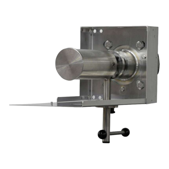
GAS 222.30
Installation and Operation Instructions
Original instructions
BE460060
Bühler Technologies GmbH, Harkortstr. 29, D-40880 Ratingen
09/2021
Tel. +49 (0) 21 02 / 49 89-0, Fax: +49 (0) 21 02 / 49 89-20
E-Mail: analyse@buehler-technologies.com
Internet: www.buehler-technologies.com
Advertisement
Table of Contents

Related Manuals for Bühler technologies GAS 222.30


Summary of Contents for Bühler technologies GAS 222.30
- Page 1 Gas Analysis Sample gas probes GAS 222.30 Installation and Operation Instructions Original instructions BE460060 Bühler Technologies GmbH, Harkortstr. 29, D-40880 Ratingen 09/2021 Tel. +49 (0) 21 02 / 49 89-0, Fax: +49 (0) 21 02 / 49 89-20 E-Mail: analyse@buehler-technologies.com...
- Page 2 Bühler Technologies GmbH, Harkortstr. 29, D-40880 Ratingen Tel. +49 (0) 21 02 / 49 89-0, Fax: +49 (0) 21 02 / 49 89-20 Internet: www.buehler-technologies.com E-Mail: analyse@buehler-technologies.com Read this instruction carefully prior to installation and/or use. Pay at- tention particularly to all advises and safety instructions to prevent in- juries.
-
Page 3: Table Of Contents
GAS 222.30 Table of Contents Introduction............................................. 2 Intended Use......................................... 2 Type Plate.......................................... 2 Scope of Delivery........................................ 2 Ordering Instructions...................................... 3 Product Description...................................... 3 Safety instructions......................................... 4 Important advice ......................................... 4 General Hazard Warnings .................................... 5 Transport and storage ........................................ 7 4 Installation and connection ...................................... 8 Installation site requirements.................................. 8... -
Page 4: Introduction
GAS 222.30 1 Introduction 1.1 Intended Use The sample gas probe is intended for installation into gas analysis systems in commercial applications. Sample gas probes are among the main components in a gas conditioning system. – Therefore also note the related drawing in the data sheet in the appendix. -
Page 5: Ordering Instructions
GAS 222.30 1.4 Ordering Instructions The item number is a code for the configuration of your unit. Please use the following model key: 4622230 0 9 9 0 0 X 0 0 X X X X X X Product Characteristics... -
Page 6: Safety Instructions
GAS 222.30 2 Safety instructions 2.1 Important advice This unit may only be used if: – The product is being used under the conditions described in the operating- and installation instructions, used according to the nameplate and for applications for which it is intended. Any unauthorized modifications of the device will void the war- ranty provided by Bühler Technologies GmbH,... -
Page 7: General Hazard Warnings
GAS 222.30 2.2 General Hazard Warnings The maximum surface temperatures of the probes also vary based on operating conditions (steam temperature, sample gas in- let temperature, ambient temperature, fluid flow rate). When used in explosive areas, also particularly note the related hazard warnings. - Page 8 GAS 222.30 DANGER Toxic, corrosive gas/condensate Sample gas/condensate may be hazardous to health. a) If necessary, ensure a safe gas/condensate discharge. b) Always disconnect the gas supply when performing maintenance or repairs. c) Protect yourself from toxic/corrosive gasses/condensate when performing mainten- ance.
-
Page 9: Transport And Storage
GAS 222.30 3 Transport and storage Only transport the product inside the original packaging or a suitable alternative. The equipment must be protected from moisture and heat when not in use. They must be stored in a covered, dry and dust-free room at a temperature between -20 °C to 50 °C (-4 °F to 122 °F). -
Page 10: Installation And Connection
GAS 222.30 4 Installation and connection 4.1 Installation site requirements Sample gas probes are intended for flange mounting. – Installation site and installation position are determined based on requirements specific to the application. – If necessary, the connection piece should be slightly tilted toward the centre of the channel. -
Page 11: Connecting The Gas Line
GAS 222.30 4.4 Connecting the Gas Line The sample gas line must be carefully and properly connected using a suitable fitting. This table provides an overview of the sample gas probe connections: Probe Reservoir Ball valve Control valve GAS 222... -
Page 12: Connecting The Blowback And Pressure Vessel (Optional)
GAS 222.30 4.5 Connecting the Blowback and Pressure Vessel (Optional) The air lines must be connected carefully and properly, using suitable fittings. If the probe is equipped with pressure vessel for efficient blowback (optional), a manual shut-off valve (ball valve) must be in- stalled in the air supply, immediately upstream from the pressure vessel. -
Page 13: Heated Pressure Vessel (Optional)
GAS 222.30 4.6.1 Heated Pressure Vessel (Optional) A heated blowback vessel may optionally be used for blowback. Heated via self-regulating PTC heating cartridge to protect against frost. The electrical connection (mains connection 115/230 V AC) uses a cubic plug as per DIN 43650. Please refer to the terminal dia- gram at the end for the connection. -
Page 14: Operation And Control
GAS 222.30 5 Operation and Control NOTICE The device must not be operated beyond its specifications. WARNING Housing or component damage Never exceed the maximum working pressure and temperature range of the drive. 5.1 Before Start-Up Before starting the device, verify –... -
Page 15: Maintenance
GAS 222.30 6 Maintenance During maintenance, remember: – The equipment must be maintained by a professional familiar with the safety requirements and risks. – Only perform maintenance work described in these operating and installation instructions. – When performing maintenance of any type, observe the respective safety and operation regulations. -
Page 16: Blowback Of The In-Situ Filter (Within The Process Stream)
GAS 222.30 WARNING Housing or component damage Never exceed the maximum working pressure and temperature range of the drive. CAUTION Drive pressurised Never loosen or remove the cover or any accessories with the drive pressurised. CAUTION Never open the drive with the function “single-acting”! This may only be done at the manufacturer’s plant. -
Page 17: Manual Blowback (Without Blowback Control)
GAS 222.30 6.1.1 Manual Blowback (Without Blowback Control) The shut-off valve in the air supply (inert gas supply) to the pressure vessel must be open. The optional pressure gauge on the pressure vessel shows the current operating pressure. – To blowback, first close the shut-off valve in the gas probe (handle below the probe/weather hood). -
Page 18: Service And Repair
GAS 222.30 7 Service and repair This chapter contains information on troubleshooting and correction should an error occur during operation. Repairs to the unit must be performed by Bühler authorised personnel. Please contact our Service Department with any questions: Tel.: +49-(0)2102-498955 or your agent If the equipment is not functioning properly after correcting any malfunctions and switching on the power, it must be inspected by the manufacturer. -
Page 19: Disposal
GAS 222.30 8 Disposal Dispose of parts so as not to endanger the health or environment. Follow the laws in the country of use for disposing of elec- tronic components and devices during disposal. BE460060 ◦ 09/2021 Bühler Technologies GmbH... -
Page 20: Appendices
GAS 222.30 9 Appendices 9.1 Technical Data Gas Probe Technical Data Probe operating temperature: max. 200 °C Ambient temperature without accessories: -20 to +80 °C Ambient temperature with accessories: Component Ambient temperature range Compressed air valve: -10 °C < T <... -
Page 21: Dimensions
GAS 222.30 9.3 Dimensions BE460060 ◦ 09/2021 Bühler Technologies GmbH... -
Page 22: Connection Diagram Heated Pressure Vessel
GAS 222.30 9.4 Connection diagram heated pressure vessel Heater Operating voltage 115-230 V AC 200 W 20 Bühler Technologies GmbH BE460060 ◦ 09/2021... -
Page 23: User Book (Please Make Copies)
GAS 222.30 9.5 User book (Please make copies) Maintained on Unit no. Operating hours Remarks Signature BE460060 ◦ 09/2021 Bühler Technologies GmbH... -
Page 24: Attached Documents
GAS 222.30 10 Attached Documents – Declaration of Conformity KX460020 – Manufacturer Declaration HX460001 – Accessories Data Sheet 461099 – RMA - Decontamination Statement Bühler Technologies GmbH BE460060 ◦ 09/2021... - Page 27 Accessories for Sample Gas Probe GAS 222 § Downstream filters § Sample tubes § Capacitive vessel § In-situ filters § Cal gas connections § Pneumatic actuators § Extensions § Adapter flanges § 3/2-way-solenoid valves § Blowback controllers Page 2 - 4 Page 8 Page 5 - 7 For general information, see data sheet “Sample gas probes GAS 222”...
- Page 28 Sample tubes, in-situ filters and extensions § Various materials § Various dimensions § Heated or nonheated extensions Sample tube T max. Material Length Part No.: 1.4571 462220010300 600°C 300 mm X X X X X X X X X X X X X X 1.4571 500 mm...
- Page 29 Sample tubes, in-situ filters and extensions § Various materials § Various dimensions § Heated or nonheated extensions In-situ filter Material T max. Length Pore size Part No.: stainless steel 600°C 237 mm 5 µm 46222303 stainless steel 237 mm 0.5 µm 46222303F* 600°C Hastelloy...
- Page 30 Sample tubes, in-situ filters and extensions § Various materials § Various dimensions § Heated or nonheated extensions Protection shield Part No.: for in-situ filter 03 462223034 for in-situ filter 04 462223044 Extensions Material Mains voltage Length G3/4 nonheated 1.4571 4622230320200 X X X X X X X X X X X X...
- Page 31 Entnahmerohre / tubes Verlängerungen / extensions ø Unbeheizt / unheated var. G3/4 Тyp var. G3/4 G3/4 0,2-2 m G3/4 var. 21,3 G3/4 G1/2 0,25-1,5m G1/2 var. G3/4 var. G3/4 var. G3/4 ø 02-0,5 24 G3/4 36 Beheizt / heated 02-1,0 1000 24 G3/4 36 Тyp ø...
- Page 32 Blowback § With ball valve or solenoid valve § Heated or nonheated § Manuell or automatic contro Ambient Capacitive vessel Part No.: temperature PAV 01 46222PAV Accessories for capacitive vessel ball valve 46222PAVKH 2/2-way-MV 24VDC* -10 ... +55°C 46222PAVMV1 2/2-way-MV 110V 50Hz -10 ...
- Page 33 Details: A) Blowback Ordering note for capacitive vessel: For attachment to GAS 222.11 / 30 / 35-U, a support is required. Ordering note for pneumatic actuator: If a blowback controller is required, only actuator P/N 46222030 is possible. We advise the installation of a position indicator switch to control the pneumatic actuator. Integrated blowback controller in the probe controller In addition to the stand-alone blowback controller (RRS), an integrated blowback controller is optionally available...
- Page 35 Downstream filter elements and further options Downstream filter Part no.: Material O-Rings Pore size 46222026 Ceramics Viton 3 µm X X X X X X X X X X X X X X Ceramics 3 µm 46222026P X X X X X X X X X X X X X X...
- Page 36 RMA-Formular und Erklärung über Dekontaminierung RMA-Form and explanation for decontamination RMA-Nr./ RMA-No. Die RMA-Nummer bekommen Sie von Ihrem Ansprechpartner im Vertrieb oder Service./ You may obtain the RMA number from your sales or service representative. Zu diesem Rücksendeschein gehört eine Dekontaminierungserklärung. Die gesetzlichen Vorschriften schreiben vor, dass Sie uns diese Dekontaminierungserklärung ausgefüllt und unterschrieben zurücksenden müssen.
- Page 37 Dekontaminierungserklärung DE000011 Bühler Technologies GmbH, Harkortstr. 29, D-40880 Ratingen 01/2019 Tel. +49 (0) 21 02 / 49 89-0, Fax: +49 (0) 21 02 / 49 89-20 E-Mail: service@buehler-technologies.com Internet: www.buehler-technologies.com...
Need help?
Do you have a question about the GAS 222.30 and is the answer not in the manual?
Questions and answers