Bühler technologies GAS 222.20 AMEX Assembly, Installation And Operation Instructions
Sample gas probes
Hide thumbs
Also See for GAS 222.20 AMEX:
- Brief instructions (32 pages) ,
- Installation and operation instruction manual (64 pages)
Table of Contents
Advertisement
Quick Links
Gas Analysis
Sample gas probes
GAS 222.20 AMEX
Installation and Operation Instructions
Original instructions
BE460044
Bühler Technologies GmbH, Harkortstr. 29, D-40880 Ratingen
01/2020
Tel. +49 (0) 21 02 / 49 89-0, Fax: +49 (0) 21 02 / 49 89-20
E-Mail: analyse@buehler-technologies.com
Internet: www.buehler-technologies.com
Advertisement
Table of Contents

Related Manuals for Bühler technologies GAS 222.20 AMEX


Summary of Contents for Bühler technologies GAS 222.20 AMEX
- Page 1 Gas Analysis Sample gas probes GAS 222.20 AMEX Installation and Operation Instructions Original instructions BE460044 Bühler Technologies GmbH, Harkortstr. 29, D-40880 Ratingen 01/2020 Tel. +49 (0) 21 02 / 49 89-0, Fax: +49 (0) 21 02 / 49 89-20 E-Mail: analyse@buehler-technologies.com...
- Page 2 Bühler Technologies GmbH, Harkortstr. 29, D-40880 Ratingen Tel. +49 (0) 21 02 / 49 89-0, Fax: +49 (0) 21 02 / 49 89-20 Internet: www.buehler-technologies.com E-Mail: analyse@buehler-technologies.com Read this instruction carefully prior to installation and/or use. Pay at- tention particularly to all advises and safety instructions to prevent in- juries.
-
Page 3: Table Of Contents
GAS 222.20 AMEX Table of Contents Introduction ............................................. 2 Intended Use......................................... 2 Type Plate.......................................... 2 Scope of Delivery........................................ 2 Ordering instructions...................................... 3 Product Description...................................... 3 Safety instructions ......................................... 4 Important advice ......................................... 4 General Hazard Warnings .................................... 5 Transport and storage ........................................ 7 4 Installation and connection ...................................... 8... -
Page 4: Introduction
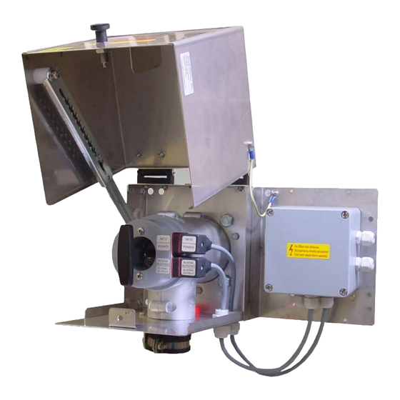
GAS 222.20 AMEX 1 Introduction 1.1 Intended Use The sample gas probe is intended for installation into gas analysis systems in commercial applications. Sample gas probes are among the main components in a gas conditioning system. – Therefore also note the related drawing in the data sheet in the appendix. -
Page 5: Ordering Instructions
GAS 222.20 AMEX 1.4 Ordering instructions The item number is a code for the configuration of your unit. Please use the following model key: 4622220 1 6 6 X 3 X 0 0 9 9 9 9 9 9 Product Characteristics... -
Page 6: Safety Instructions
GAS 222.20 AMEX 2 Safety instructions 2.1 Important advice This unit may only be used if: – the product is being used under the conditions described in the operating- and installation instructions, used according to the nameplate and for applications for which it is intended. any unauthorized modifications to the device will void the war- ranty provided by Bühler Technologies GmbH,... -
Page 7: General Hazard Warnings
GAS 222.20 AMEX 2.2 General Hazard Warnings The maximum surface temperature of the probes solely varies by operating conditions (steam temperature, sample gas inlet temperature, ambient temperature, fluid flow rate). For use in explosive areas please particularly note the related hazard warn- ings. - Page 8 Ignition of dust layers! When using the device in a dusty environment, routinely clean dust from all compon- ents. Also remove the dust layer under the thermal insulation on the GAS 222.20 AMEX probe. The ignition temperature resp. smouldering temperature of flammable dusts resp. dust layers present must be considerably higher than the maximum surface temperature of the probe (observe applicable standards and statutory regulations).
-
Page 9: Transport And Storage
GAS 222.20 AMEX 3 Transport and storage Only transport the product inside the original packaging or a suitable alternative. The equipment must be protected from moisture and heat when not in use. They must be stored in a covered, dry and dust-free room at a temperature between -20 °C to 50 °C (-4 °F to 122 °F). -
Page 10: Installation And Connection
Explosion hazard due to ignition of dust When using the device in a dusty environment, routinely clean dust from all compon- ents. Also remove the dust layer under the thermal insulation on the GAS 222.20 AMEX probe. The ignition temperature resp. smouldering temperature of flammable dusts resp. dust layers present must be considerably higher than the maximum surface temperature of the device (observe applicable standards and statutory regulations). -
Page 11: Installing The Outlet Filter
GAS 222.20 AMEX 4.4 Installing the outlet filter NOTICE The outlet filter and the O-ring for the handle must be inserted prior to first startup. Operating without outlet filter prohibited! Attach an O-ring suitable for the expected ambient temperature to the handle. -
Page 12: Connecting The Gas Line
GAS 222.20 AMEX 4.6.1 Connecting the Gas Line Please note the following items when connecting the sample gas line (NPT 1/4") on heated probes to prevent thermal bridges: – Choose the shortest possible screw connection. – Shorten the connection pipe for the sample gas line as much as possible. To do so, remove the insulation around the sample gas line. - Page 13 GAS 222.20 AMEX NOTICE The thermal alarm contact must be connected energy-limited! = 30 V, I = 100 mA) WARNING High voltage Damage to the device in case of insulation testing Do not proceed insulation tests with high voltage to the device as a whole! Electric strength test The necessary tests of all assemblies required to be tested were carried out at the factory (test voltage 1 kV or 1.5 kV depending...
-
Page 14: Operation And Control
GAS 222.20 AMEX 5 Operation and Control NOTICE The device must not be operated beyond its specifications. NOTICE The weather hood must be closed during operation! WARNING Housing or component damage Never exceed the maximum working pressure and temperature range of the drive. -
Page 15: Maintenance
GAS 222.20 AMEX 6 Maintenance – Damaged parts must be replaced immediately. – Regularly check the function of the electrical protection. During maintenance, remember: – The equipment must be maintained by a professional familiar with the safety requirements and risks. -
Page 16: Maintaining The Filter Element
Explosion hazard due to ignition of dust When using the device in a dusty environment, routinely clean dust from all compon- ents. Also remove the dust layer under the thermal insulation on the GAS 222.20 AMEX probe. The ignition temperature resp. smouldering temperature of flammable dusts resp. dust layers present must be considerably higher than the maximum surface temperature of the device (observe applicable standards and statutory regulations). -
Page 17: Maintenance Schedule
– Opening the weather hood and removing dust. Operator (layer must be < 3 mm) On GAS 222.20 AMEX also remove the insulation and dust. Heating tape every 8000 h – Check insulation resistance and the electrical protection. Operator Filter every 8,000 h –... -
Page 18: Service And Repair
GAS 222.20 AMEX 7 Service and repair This chapter contains information on troubleshooting and correction should an error occur during operation. Repairs to the unit must be performed by Bühler authorised personnel. Please contact our Service Department with any questions: Tel.: +49-(0)2102-498955 or your agent... -
Page 19: Disposal
GAS 222.20 AMEX 8 Disposal The applicable national laws must be observed when disposing of the products. Disposal must not result in a danger to health and environment. The crossed out wheelie bin symbol on Bühler Technologies GmbH electrical and electronic products indicates special disposal notices within the European Union (EU). -
Page 20: Appendices
GAS 222.20 AMEX 9 Appendices 9.1 Technical Data Gas Probe Technical Data Self-regulating temperature: 130 °C (T3)/70 °C (T4) Ambient temperature: -20 to +80 °C Low temperature alarm: Contact open at operating temperature, closes at < 95 °C (T3) resp. < 50 °C (T4); U... -
Page 21: Dimensions
GAS 222.20 AMEX 9.4 Dimensions BE460044 ◦ 01/2020 Bühler Technologies GmbH... -
Page 22: List Of Chemical Resistance
GAS 222.20 AMEX 9.5 List of chemical resistance Materials of your device in contact with media are printed on the type plate. Formula Medium Concentration Teflon® FFKM Viton® PTFE COCH Acetone Benzol Chlorine 10 % wet Chlorine 97 % Ethane... -
Page 23: User Book (Please Make Copies)
GAS 222.20 AMEX 9.6 User book (Please make copies) Maintained on Unit no. Operating hours Remarks Signature BE460044 ◦ 01/2020 Bühler Technologies GmbH... -
Page 24: Attached Documents
GAS 222.20 AMEX 10 Attached Documents – Certificate of Compliance: CSA 1728394 – Accessories Data Sheet 461099 – RMA - Decontamination Statement Bühler Technologies GmbH BE460044 ◦ 01/2020... - Page 25 Certificate of Compliance 1728394 231516 Certificate: Master Contract: 2361506 November 18, 2010 Project: Date Issued: Issued to: Bühler Technologies GmbH Harkortstr. 29 Ratingen, D-40880 Germany Attention: Christopher Sungergeld The products listed below are eligible to bear the CSA Mark shown with adjacent indicators 'C' and 'US' for Canada and US or with adjacent indicator 'US' for US only or without either indicator for Canada only.
- Page 26 1728394 231516 Certificate: Master Contract: 2361506 November 18, 2010 Project: Date Issued: APPLICABLE REQUIREMENTS CAN/CSA C22.2 No. 0-M91 (R2001) - General Requirements - Canadian Electrical Code, Part II CSA Std C22.2 No. 142-M1987 Process Control Equipment CSA Std C22.2 No. 213-M1987 Non-Incendive Electrical Equipment for Use in Class I, Division 2 Hazardous Locations UL Std No.
- Page 27 Accessories for Sample Gas Probe GAS 222 § Downstream filters § Sample tubes § Capacitive vessel § In-situ filters § Cal gas connections § Pneumatic actuators § Extensions § Adapter flanges § 3/2-way-solenoid valves § Blowback controllers Page 2 - 4 Page 8 Page 5 - 7 For general information, see data sheet “Sample gas probes GAS 222”...
- Page 28 Sample tubes, in-situ filters and extensions § Various materials § Various dimensions § Heated or nonheated extensions Sample tube T max. Material Length Part No.: 1.4571 462220010300 600°C 300 mm X X X X X X X X X X X X X X 1.4571 500 mm...
- Page 29 Sample tubes, in-situ filters and extensions § Various materials § Various dimensions § Heated or nonheated extensions In-situ filter Material T max. Length Pore size Part No.: stainless steel 600°C 237 mm 5 µm 46222303 stainless steel 237 mm 0.5 µm 46222303F* 600°C Hastelloy...
- Page 30 Sample tubes, in-situ filters and extensions § Various materials § Various dimensions § Heated or nonheated extensions Protection shield Part No.: for in-situ filter 03 462223034 for in-situ filter 04 462223044 Extensions Material Mains voltage Length G3/4 nonheated 1.4571 4622230320200 X X X X X X X X X X X X...
- Page 31 Entnahmerohre / tubes Verlängerungen / extensions ø Unbeheizt / unheated var. G3/4 Тyp var. G3/4 G3/4 0,2-2 m G3/4 var. 21,3 G3/4 G1/2 0,25-1,5m G1/2 var. G3/4 var. G3/4 var. G3/4 ø 02-0,5 24 G3/4 36 Beheizt / heated 02-1,0 1000 24 G3/4 36 Тyp ø...
- Page 32 Blowback § With ball valve or solenoid valve § Heated or nonheated § Manuell or automatic contro Ambient Capacitive vessel Part No.: temperature PAV 01 46222PAV Accessories for capacitive vessel ball valve 46222PAVKH 2/2-way-MV 24VDC* -10 ... +55°C 46222PAVMV1 2/2-way-MV 110V 50Hz -10 ...
- Page 33 Details: A) Blowback Ordering note for capacitive vessel: For attachment to GAS 222.11 / 30 / 35-U, a support is required. Ordering note for pneumatic actuator: If a blowback controller is required, only actuator P/N 46222030 is possible. We advise the installation of a position indicator switch to control the pneumatic actuator. Integrated blowback controller in the probe controller In addition to the stand-alone blowback controller (RRS), an integrated blowback controller is optionally available...
- Page 35 Downstream filter elements and further options Downstream filter Part no.: Material O-Rings Pore size 46222026 Ceramics Viton 3 µm X X X X X X X X X X X X X X Ceramics 3 µm 46222026P X X X X X X X X X X X X X X...
- Page 36 RMA-Formular und Erklärung über Dekontaminierung RMA-Form and explanation for decontamination RMA-Nr./ RMA-No. Die RMA-Nr. bekommen Sie von Ihrem Ansprechpartner im Vertrieb oder Service. Bei Rücksendung eines Altgeräts zur Entsorgung tragen Sie bitte in das Feld der RMA-Nr. "WEEE" ein./ You may obtain the RMA number from your sales or ser- vice representative.
- Page 37 Dekontaminierungserklärung DE000011 Bühler Technologies GmbH, Harkortstr. 29, D-40880 Ratingen 12/2022 Tel. +49 (0) 21 02 / 49 89-0, Fax: +49 (0) 21 02 / 49 89-20 E-Mail: service@buehler-technologies.com Internet: www.buehler-technologies.com...
Need help?
Do you have a question about the GAS 222.20 AMEX and is the answer not in the manual?
Questions and answers