
Related Manuals for Metacon-Next FirePro V4

Summary of Contents for Metacon-Next FirePro V4
- Page 1 User manual FirePro V4 Type: HW V4.4 SW V5.2 Version: 20220628 PLEASE CAREFULLY READ THIS USER MANUAL BEFORE YOU USE THE CONTROLLER. STORE THIS INFORMATION SO THAT IT CAN BE REFERENCED IN THE FUTURE!
- Page 2 © 2022 RDA-BV. This manual is translated from the original Dutch manual, In the event of discrepancies between the two, the Dutch version shall prevail. Subject to changes and typing errors. The information in this manual is subject to change and can be revised if necessary. No rights can be claimed from the provided information.
-
Page 3: Foreword
Foreword 1. Foreword This manual is intended as a guide when using the FirePro controller in combination with a “Fail-safe” drive unit type FS by GFA Elektromaten. We would like to thank you for working with us, and for the trust that you have placed in our product. - Page 4 Gives the user suggestions or advice that make a procedure easier or more practical to execute. COMMENT A general comment that possibly offers extra economic benefits. ENVIRONMENT Guidelines that must be followed when using hazardous substances and when recycling products and materials.
-
Page 5: Table Of Contents
Contents Foreword .......................... 3 Foreword ..........................3 Using the manual ........................3 Target group ..........................3 Used symbols .......................... 3 Contents ........................... 5 Introduction ....................... 8 1.1 Intended use..........................8 1.2 Forbidden use .......................... 8 1.3 Life span of batteries ....................... 9 1.4 Type designation ........................ - Page 6 8.11 Parameter series 9, registration .................... 45 (Error) Messages ...................... 46 9.1 Status messages ........................46 9.2 Error messages (for questions: +31 (0) 182 23 15 25 or service@metacon-next.com) ..46 10 Configuration fire/smoke detector ................50 10.1 FD (fire detection) function (alarm/emergency) ..............50 10.2 Continue running if battery empty (only for digital end switch DES) ........
- Page 7 Spare parts ..........................57 Installation details (to be filled in by the installation engineer) ........... 58 Maintenance sheet ....................... 59...
-
Page 8: Introduction
1 Introduction 1.1 Intended use Safe use of this controller can only be guaranteed if it is used for its intended purpose. The manufacturer is not responsible for damage that is caused by external components or failure to comply with these instructions. Modifications are only permitted in consultation with the manufacturer. -
Page 9: Life Span Of Batteries
conformity with harmonized standards, it is not possible to foresee all dangers. That is why people should only enter the danger zone if this is truly necessary. If there are doubts about the installation, do not continue and contact the supplier for clarification. All information in this document (photos, drawings, characteristics and dimensions) may be subject to change without prior notification. -
Page 10: Technical Details
Figure 2 Position of the type plate 1.5 Technical details Table1 Technical details Data Explanation Weight 10 kg Height 400 mm Width 300 mm Depth 150 mm Electricity consumption Max. 2.2 kW Power 3N~400Vac +/- 10%, 50/60 Hz 3~230Vac +/- 10%, 50/60 Hz 1N~230Vac +/-10%, 50/60 Hz Fuse Max. -
Page 11: Description
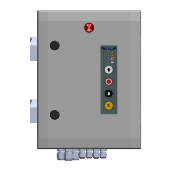
2 Description 2.1 Front view Figure 3 Front view Table 2 Layout front view Component Casing Signal transmitter Front panel Cable inlet 4 x M16 Ventilation Lock Cable inlet 2 x M20... -
Page 12: Internal View
2 batteries (12V-5.2Ah). The lid of the cabinet has a control panel that features 4 status LEDs. Figure 4 Internal view Table 3 Layout internal view Component Casing Ventilation FirePro V4 control circuit board Power/charger Signal transmitter board (P-CAP) Battery Battery attachment... -
Page 13: Description Of Controller
WARNING Only use accessories that comply with the applicable standards. 2.3 Description of controller The FirePro is a controller for vertically-operating fire and/or smoke-proof doors (for example, shutter sectional doors and fire hatches) that feature a FailSafe drive unit (FS series) by GfA- Elektromaten. -
Page 14: Functioning
3 Functioning 3.1 Functioning The FirePro covers a cabinet with a control circuit board in combination with a power supply/charger. This controller can operate as “hold to run” as well as automatically when in normal mode. Operation in normal mode is possible using the buttons on the cabinet and/or the external up, stop and down controls. - Page 15 In case of a fire alarm, the door will be released immediately or after an extended period of time. There are two fire alarm inputs. The menu can be used to decide whether or not they must be reset so that the door is restored to normal operating mode. If a fire alarm input must be reset, a time delay can be selected for releasing the door.
- Page 16 If the safety edge or photocell safety feature is activated in case of closure during a fire alarm, power failure or almost empty battery, the controller will regard the concerned safety feature to be faulty if it is activated continuously for 120 seconds (factory setting) or longer, and the door will then continue closing without the safety feature! It is possible to connect an escape button, whereby the door can be opened in case of a fire alarm (if mains power is still present), to allow someone to escape.
-
Page 17: Safety
4 Safety 4.1 Safety systems Only use safety products that comply with the applicable norms. Examples include: safety edges, photocells, smoke detectors and heat detectors. 4.2 Safety arrangements Only qualified personnel, who possess the required equipment and knowledge, are permitted to perform activities on this controller. -
Page 18: Meaning Of Warning Signals
WARNING The controller can only be managed by people who have read the user manual and are thus sufficiently familiar with the functioning, operation, maintenance, etc. of the controller, as described in this user manual. DANGER It is forbidden to remove, bypass or deactivate safety features and protective devices. CAUTION Make sure that all safety features are correctly activated again after all maintenance activities and other interventions. -
Page 19: Signs And Symbols
Table 5 Warning signals power/charger. Warning signal Symbol Meaning Mains fail LED on: No mains power Batt Low LED on: Low battery voltage Batt O/C LED on: No battery present Charger loss LED on: Error message charger Batt O/C + Batt. low LED on: High impedance batteries (replace batteries) Status LED flashing: charger OK... -
Page 20: Transport And Storage
5 Transport and storage 5.1 Transporting the device The device will be delivered by specialized companies and will be assembled and configured by an authorized installation engineer. As the operator, you are responsible for monitoring requirements at the configuration location. 5.2 Storing the device for a long period Environment temperatures above 40°C or below 5°C during use or above 40°C or below -15°C during storage can have an impact on the life span and/or correct operation of the batteries. -
Page 21: Assembly And Installation
6 Assembly and installation The following points must be inspected and checked to make sure that the controller is assembled in a proper and professional manner: Assembly of the controller must only take place indoors on a dry, vibration-free and flat surface. Make sure that the maximum permissible load of walls and attachments has not been exceeded. - Page 22 The installation engineer must hand over a fully completed and signed inspection report to the end user. Figure 5 Assembly instructions...
-
Page 23: Commissioning
7 Commissioning Figure 6 Circuit board FirePro V4... - Page 24 Table 7 Terminal numbering Terminal Description Connect number Mains power L1, L2, L3, N Ground Brake + = 4 - = 5 Brake interruption 1 = Com 2 = Nc Voltage to power supply L1 = 230 Vac N = neutral 2 potential-free programmable contacts 1 + 4 = Com Output 1 (par.
-
Page 25: Commissioning
7.1 Commissioning The end switches of the drive unit must first be connected before power is switched on for the first time. The controller will then automatically recognize the used end switches when switched on, and the controller will configure accordingly. It is not possible to move the door if the controller is not configured correctly. -
Page 26: Configure "Over-Close Nes Position
7.3 Configure “over-close NES position” If necessary, configure the extra end switch S6 as selected in the menu (how the switch will be used in case of fire). End switch S6 can be used in 3 ways: As “over-close” end switch, so that the door runs further than normal in case of fire alarm, smoke alarm or lack of battery power;... -
Page 27: Configuring End Switches Des
7.5 Configuring end switches DES Start programming: Check direction of rotation Change direction of rotation, if necessary Move to OPEN final limit position Save OPEN final limit position Move to CLOSED final limit position Save CLOSED final limit position Once the end position has been set, the status of the door will be shown on the display using the symbols below. -
Page 28: Connection
8 Connection 8.1 Terminal connections Mains power Mains power X1 + ground X2 3N~400Vac 3~230Vac 1~230Vac Brake Brake X3 Connect The 2-pin connector for the FirePro motor cable is connected to X3. This is used to operate the brake. When removing wires on the motor side, make sure that the + (terminal 11) and –... -
Page 29: Potential-Free Contacts
Potential-free contacts Potential-free contacts X6 Connect X6 features two outputs as potential-free changeover switches. They can be configured for various functions via parameters 5.1 and 5.2. Programmable input Programmable input X10 Connect This input can be programmed using parameter 2.6 Photocell Photocell X11 A 8 reflection photocell... -
Page 30: Pnp Light Curtain
PNP light curtain LIGI 01 PNP light curtain X11 Description Transmitter X11-1 = Brown X11-2 = Blue X6-4 = 24 vdc X6-5 = Black Recipient X11-1 = Brown X11-2 = Blue X11-3 = Black Connect both white wires to each other Pass door / Slack cable / cable breakage X12 Pass door / Slack cable / cable breakage X12 Connect X12 is an input that features a stop function. -
Page 31: Ose Light Curtain
10. OSE light curtain Transmitter LIGI 07 OSE light Receiver LIGI 07 OSE light curtain Description curtain X14 1 = Brown 2 = Blue 3 = Black 4 = White 11. External controls External controls X16 Connect X16 can be used to connect external UP-STOP-DOWN controls. -
Page 32: Fire Alarm Input
13. Fire alarm input FDC Fire alarm input X18 Connect Fire alarm input 2 can be connected as potential-free N.C. (break) contact in series with an 8.2kΩ resistor or as a potential-free N.C. contact. This choice can be made in the menu for parameter 5.7. -
Page 33: Control Panel
16. Control panel Control panel lid X21 Connect The control panel is connected to connector X21 using a flat cable. 17. RJ 45 connector RJ 45 Connector X22 Connect RJ 45 connector for connecting a future expansion of the RDA Updater. 18. -
Page 34: Control Cable Firepro V4
8.2 Control cable FirePro V4 Figure 8 FirePro V4 Control cable Table 5 Components Control cable FirePro V4 Number Description Cable DES / NES connector Phase connector drive unit Brake connector drive unit Wire-end ferrule DES /NES pin for connector... -
Page 35: Operating Instructions
8.3 Operating instructions The circuit board features 3 push buttons under the display, namely: “˅”, “˄” and “stop/ok” (see image). When in normal operation, these buttons work as up-stop-down controls. A password must first be entered before the menu can be accessed (the default is 99; can be modified in menu 9.6). -
Page 36: Parameter Series 0, Basic Settings
8.4 Parameter series 0, basic settings Parameter Description Settings Exit menu Exit the menu by pressing “stop/ok” Operation mode .1) “Hold to run” open & close .2) Automatic open, “hold to run” close .3) Automatic open & close “hold to run” close not possible with external controls .4) Automatic open &... - Page 37 Parameter Description Settings .7) Photocell active - Safety edge active. Open completely if mains power is present. If mains power is not present, stop and then close again after the configured time (parameter 0.6). Delay activation of 0 – 60 Seconds 3 sec.
-
Page 38: Parameter Series 1, (End) Position Settings
8.5 Parameter series 1, (end) position settings Parameter Description Settings End position open Select the desired door position and save using stop/ok button. Stop button on lid to cancel. End position closed Select the desired door position and save using stop/ok button. Stop button on lid to cancel. -
Page 39: Parameter Series 2, Action Settings
8.6 Parameter series 2, action settings Parameter Description Settings Duration monitoring 1 to 240 seconds 120 sec. Impulse function .1) Inactive during opening (parameter 0.1 = .2) Stop during opening Automatic opening Automatic close time in 0 = Automatic close deactivated normal operation. -
Page 40: Parameter Series 3, Emergency Settings
Parameter Description Settings photocell position and ignore the photocell during closing from that point. 8.7 Parameter series 3, emergency settings Parameter Description Settings Choice end position door .1) Use normally closed end switch; deactivate end bottom during switch S6. alarm/emergency in .2) Use end switch (S6) as “Over-close”. -
Page 41: Parameter Series 4, Warning Settings
Parameter Description Settings function of safety edge .1) Continue to close without safety edge. and/or photocell after .2) Open again for 2 seconds and then stop reaching the maximum (only possible if mains power is present). number of attempts configured in parameter .3) Only stop. - Page 42 Parameter Description Settings configured position. Delay time response to 0 to 10 minutes. 0 min. start emergency/accident alarm. Choice reset in case of fire .1) No reset needed. alarm .2) Reset needed for fire alarm input 1. .3) Reset needed for fire alarm input 2. .4) Reset needed for fire alarm input 1 and 2.
-
Page 43: Parameter Series 5, Output Settings
8.9 Parameter series 5, output settings Parameter Description Settings Function output 1 .1) Switch off (terminals X 6) .2) Activated during pre-warning in case of door movement. .3) Only activated in case of door movement. .4) Only activated in case of fire alarm or close for power failure, if this has been selected. - Page 44 Parameter Description Settings 2.5) Obstacle detection; activated if the photocell and/or safety edge input is interrupted/activated for a configured time (parameter 5.4). Choice after .1) Door closes until an open button, sensor input or stop button is deactivation fire operated. alarm(s) .2) Door stops immediately.
-
Page 45: Parameter Series 8, Maintenance Settings
8.10 Parameter series 8, maintenance settings Parameter Description Settings Number of cycles before 1 to 99 maintenance (per 1,000 cycles, setting possible from 1,000 (= 1) to 99,000 (= 99)) Maintenance counter .1) Deactivated. Activated; (message and close door when counter reaches 0) .3) Activated;... -
Page 46: Error) Messages
Maintenance cycle reached. Perform maintenance on the door and configure par. 8.5 again. The LED on the lid will flash red/green alternately. 9.2 Error messages (for questions: +31 (0) 182 23 15 25 or service@metacon-next.com) Request Description Recommendation/Explanation F 1.3 Safety chain drive unit DES. - Page 47 F2.2 During automatic closure, the door has Check if there is an obstacle in the door opening. If this reached the configured number of is the case, remove the obstacle and enter a new close attempts (par.2.5) command. If there is no obstacle, check if the safety edge is still working correctly and if the pre-end switch closed is correctly configured.
- Page 48 If the signal on the selected relay contact of X6 is not broken, this will be regarded as a negative test. The door can now only close “hold to run”. Check the connections of the light curtain and the light curtain itself.
- Page 49 F 7.2 Error in charger. This message is shown if the power/charger is no longer able to charge the batteries. Replace the batteries and/or the power/charger. F 7.3 Batteries’ impedance too high. The internal resistance of the batteries is too high. Check the connection between the batteries and the power/charger.
-
Page 50: Configuration Fire/Smoke Detector
10 Configuration fire/smoke detector 10.1 FD (fire detection) function (alarm/emergency) If the FDC (Fire Detection Contact) is activated, the door will close because the voltage to the electric brake on the drive unit will be cut. Under the default factory setting, the door will lower until it reaches the end switch close. -
Page 51: Maintenance Counter
C.S. will appear on the display. 10.4 Smoke gasket The following settings are needed to control FirePro V4 fire doors with a smoke gasket: One of the potential-free contacts must be configured so that it is activated if the door is closed via the fire input(s) where the gasket must be inflated. -
Page 52: Maintenance
11 Maintenance In order to guarantee effective operation, the user must perform an inspection on the whole system, including all components, every 3 months. When doing so, confirm that the door functions completely during normal operation and closes as required in case of emergencies and/or loss of power. This inspection must be documented and stored by the user. -
Page 53: Maintenance Instructions
11.1.2 Maintenance instructions The instructions below must be followed when performing maintenance:: Visual inspection controller: Make sure that the controller has no damage or shortcomings. Make sure that the mains power cable is not damaged. If this is damaged, replace it with an original cable from the manufacturer. -
Page 54: Decommissioning And Disposal
12 Decommissioning and disposal 12.1 Decommissioning To decommission the controller, the mains power must be cut and the poles of the batteries must be disconnected. Performing activities on the controller while it is still being powered is perilous and can cause serious injury! WARNING Only use the controller for the purpose for which it was designed. -
Page 55: Appendices
Appendices 5. EC declaration or Declaration of incorporation As referred to in machinery directive 2006/42/EC for partly completed machinery, appendix II.1.B. As referred to in the EMC directive 2014/30/EU RDA bv, located at Spoorakkerweg 6 in 5071 NC Udenhout, hereby declares that the product mentioned below complies with the above-mentioned EC directive and is only intended to be incorporated into a door system as described in the user manual. - Page 56 Essential health and safety requirements concerning the design and construction of the machine according to the Machinery Directive 2006/42/EC appendix I implemented / complied appendix I implemented / complied appendix I implemented / with with complied with General principles 1.5.11 3.6.1 1.5.12 3.6.2...
- Page 57 6. Spare parts Table 7 Spare parts Part number Description Additional information FirePro V4, control circuit board - HWx.xx Power/charger 24 Vdc battery 12 Vdc, 5.2 Ah Panel key Indicator/buzzer P-cap V2 Velcro 400 x 30 mm, flame retardant Fuse F1 6.3 Ampère Slow...
- Page 58 7. Installation details (to be filled in by the installation engineer) Details of the Door Order number Serial number Location Date of Installation Details Manufacturer Name Address Telephone number Email Website Details installation engineer Name Address Telephone number Email Website Details Controller Manufacturer Product number...
- Page 59 8. Maintenance sheet Date Done by Maintenance done...
- Page 60 Your installation engineer: Metacon-Next B.V. | Zuidbaan 450| 2841 MD Moordrecht| T +31 (0) 182 23 15 25 | E service@metacon-next.com |...
Need help?
Do you have a question about the FirePro V4 and is the answer not in the manual?
Questions and answers