Table of Contents
Advertisement
Quick Links
Advertisement
Table of Contents

Related Manuals for fischertechnik COMPUTING ROBO TX ElectroPneumatic


Summary of Contents for fischertechnik COMPUTING ROBO TX ElectroPneumatic
-
Page 2: Table Of Contents
COMPUTING ROBO TX ElectroPneumatic Contents Welcome to the fischertechnik Computing World About this Activity Booklet History Principles of pneumatics Producing motion with air Generating and storing compressed air – diaphragm pump as compressor Switching compressed air – solenoid valves Interaction of electrical and pneumatic circuits... -
Page 3: Welcome To The Fischertechnik Computing World
- and so forth - step for step. So don't be timid, we will plunge into the fischertechnik Computing World together and then go on to more complex tasks. -
Page 4: History
Producing motion with air A number of pneumatic cylinders are included in the ElectroPneumatic construction set. You need one of them for the first experiment. Pneumatic cylinder from fischertechnik Hose connection A The piston rod with piston can move and is sealed along the cylin- Hose connection B der wall by gaskets. - Page 5 COMPUTING ROBO TX ElectroPneumatic The air moves this cylinder in one direction only. It is returned to its initial position by the force of a spring. Such cylinders are called "single acting cylinders". Circuit diagram of single Note: acting cylinder The connection you use to move out (extend) the piston is designated "A";...
- Page 6 COMPUTING ROBO TX ElectroPneumatic Switching compressed air – solenoid valves In pneumatics the purpose of a valve is to control the flow of air to the pneumatic cylin- der so that the cylinder either extends or retracts. The valve can be actuated either by hand, pneumatically or electromagnetically as on your technical models.
-
Page 7: Robo Pro Control Software
COMPUTING ROBO TX ElectroPneumatic In the illustration the electrical part is on the left and the pneumatic stage on the right. The electrical part consists of a +9V power source, a pushbutton and the valve coil (electromagnet). The pneumatic stage consists of the compressed air source, the valve and the cylinder. -
Page 8: Compressed Air Motor
COMPUTING ROBO TX ElectroPneumatic Compressed air motor For your first model, build the "compressed air motor" as described in the assembly instructions. A compressed air or pneumatic motor functions similar to a steam engine. It has a cylinder, a piston, an intake and an outlet. -
Page 9: Programming
COMPUTING ROBO TX ElectroPneumatic Task 3: Testing the model with the ROBO TX Controller Connect the ROBO TX Controller to the power supply and switch it on. Con- nect the ROBO LT Controller to the PC. Then start the ROBO Pro software. Activate the "Test"... -
Page 10: Color Sorting Robot
Color sensors are used frequently in automation technology. This is done, for example, to examine the color or the color imprint to ensure that the correct components are installed. The fischertechnik color sensor transmits red light, which is reflected with different strength from different colored surfaces. The quantity of reflected light is measured by the phototransistor and output as a voltage between 0 V and 10 V. -
Page 11: Sensors And Actuators
B leads to the suction cup. When the valve is actuated, both pistons are pushed forward. If fischertechnik suction cup the suction cup is positioned on a part, the air is sucked in by the two pistons producing a vacuum. -
Page 12: Color Recognition Subprogram
COMPUTING ROBO TX ElectroPneumatic Task 2 - Control program - ROBO Pro Level 2 A light barrier is located at the end of the chute to recognize whether a part is pres- ent. If so, the gripper arm picks up the part and places it on the color sensor for recognition of the color. -
Page 13: Ball Obstacle Course With Vacuum Picker Arm
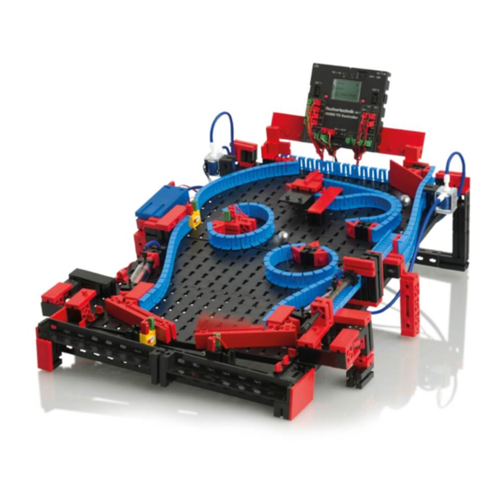
COMPUTING ROBO TX ElectroPneumatic Ball obstacle course with vacuum picker arm With this model the vacuum picker arm automati- cally returns balls from the end to the start of an obstacle course. Build the model according to the assembly instructions and wire the electrical and pneumatic components according to the circuit diagram. -
Page 14: Variables
COMPUTING ROBO TX ElectroPneumatic Tips The position of the gripper arm can be defined with the aid of the "pulse counter" command. The values required can be entered in the interactive window. If the ideal position is between two pulses, you can also adjust the start or end position of the balls by moving one or more of the building blocks so that the gripper picks up or puts down the ball reliably. -
Page 15: Pinball Machine
COMPUTING ROBO TX ElectroPneumatic Pinball machine Now you can play pinball! Build the model according to the assembly instructions and wire the electrical and pneu- matic components according to the circuit diagram. During assembly pay attention to accuracy when installing the parts, connecting the hoses and wiring the electrical components. - Page 16 COMPUTING ROBO TX ElectroPneumatic Task 1 - Pinball control program - ROBO Pro Level 3 A ball is shot into the game field from a launching pad. The ball then runs through TX display program call the obstacle course set up. When it passes the light barrier or comes close to the color sensor, points are given.
- Page 17 COMPUTING ROBO TX ElectroPneumatic Keeping score: You can use various systems to assign points. In the program used as an example the program waits 5 seconds after the light barrier is interrupted for the first time and simultaneously counts how many times the light barrier is interrupted during this time.
- Page 18 ElectroPneumatic...
Need help?
Do you have a question about the COMPUTING ROBO TX ElectroPneumatic and is the answer not in the manual?
Questions and answers