
Related Manuals for fischertechnik ROBOTICS TXT Smart Home


Summary of Contents for fischertechnik ROBOTICS TXT Smart Home
- Page 1 Begleitheft Activity booklet Manual d‘accompagnement Begeleidend boekje Cuaderno adjunto Folheto Libretto di istruzioni Сопроводительная инструкция 附带说明书...
- Page 2 ROBOTICS Smart Home Robotics Sensor Station IoT Welcome to the fischertechnik World of ROBOTICS About this Activity Booklet Introduction Digitization Internet of Things Smart Home Industry 4.0 Some General Information Electricity Component Explanations Software ROBO Pro 4.4.x ROBOTICS TXT Controller...
-
Page 3: Table Of Contents
ROBOTICS Smart Home Robotics Sensor Station IoT Comfort Sensor Frost Monitor Mold Monitor Air Quality Sensor Stationary Camera with Environmental Sensor – Data Logging Barometer Sensor Station with Movable Camera Surveillance Camera Cloud Computing Trouble Shooting Interface Test Cables and Wiring Short Circuits Errors in the Program Last Sources for Help... - Page 4 Smart Home Robotics Sensor Station IoT Welcome to the fischertechnik World of ROBOTICS Hello! With this product “ROBOTICS TXT Smart Home” or “Robotics Sensor Station IoT” you can solve fascinating problems under the motto Smart Home, Digitization and Internet of Things.
- Page 5 ROBOTICS Smart Home Robotics Sensor Station IoT About this Activity Booklet This PDF activity booklet has a number of functions, which are not present in the printed booklet and which may already be familiar to you from the Internet. Links within the Booklet ▯...
- Page 6 ROBOTICS Smart Home Robotics Sensor Station IoT Introduction Before starting with the models and your programming, I would like to entice you with a small preview of these interesting projects. This also includes a glimpse into the new control-related features with their specific technical names, to be precise, what do we mean by “Smart Home”, Internet of Things”, “Digitization”...
- Page 7 ROBOTICS Smart Home Robotics Sensor Station IoT digital radio signals, which are then used by a computer to calculate the route to your destination and display it on the GPS screen. Internet of Things This is certainly a term you will encounter often in the next few years. But what does the term “Internet of Things”...
- Page 8 ROBOTICS Smart Home Robotics Sensor Station IoT Industry 4.0 We frequently call this the fourth industrial revolution. Although many people have probably never heard of this term, we have been living with it for some time now. ▯ It all began at the end of the 18 century with the steam engine.
- Page 9 ROBOTICS Smart Home Robotics Sensor Station IoT address and placed in a storage location for shipment. After reaching the shipping department, it is automatically sent to the proper shipping agent. The first human the album comes into contact with is the driver of the package van as he delivers it to the customer.
- Page 10 ROBOTICS TXT Controller or the rechargeable battery. Component Explanations The construction set contains all of the following First, it contains numerous fischertechnik building blocks, as well as motors, indicator lights and sensors and colored assembly instructions for building various models. Actuators Actuators are all components, which can perform some type of action.
- Page 11 ROBOTICS Smart Home Robotics Sensor Station IoT Sensors Sensors are so to speak the counterpart to the actuators Actuators. This is because they do not perform any actions, but react to certain situations and events. For example, a pushbutton reacts when pressed, allowing an electric current to flow or interrupting its flow.
- Page 12 As you know, many of the components in the ROBOTICS TXT SmartHome Set need electricity to operate, so naturally you also need a power supply for the TXT Controller. The fischertechnik power pack is best suited for this. It is not included in the construction set. A Few Tips Experimenting makes the most fun when the experiments also work.
- Page 13 ▯ create and start your first simple program with ROBO Pro Since you will be working particularly with the ROBO Pro Software in addition to the fischertechnik components themselves, you should be familiar with the details for writing programs. And because this is explained very clearly in ROBO Pro Help...
- Page 14 ROBOTICS Smart Home Robotics Sensor Station IoT Starting ROBO Pro Start the ROBO Pro program. The following working display appears. To create a new program, click on the “New” button with the mouse. ROBO Pro then switches over to the programming mode. You can tell this, because the program monitor displays a dot matrix.
- Page 15 ROBOTICS Smart Home Robotics Sensor Station IoT To save a program click on the “Save” button with the mouse. ROBO Pro automatically switches to Explorer and displays your computer’s table of contents. Here you can select a folder, such as “ft Save programs”...
- Page 16 ROBOTICS Smart Home Robotics Sensor Station IoT Light with brightness sensor The first model you built according the assembly instructions, serves to control an outdoor light depending on the ambient brightness. To program this, use programming level 1 for your first program. Photo Resistor Use a photo resistor for the sensor.
- Page 17 ROBOTICS Smart Home Robotics Sensor Station IoT Project 1 As soon as it becomes dark, the lights should turn on. It will be necessary for you to find the threshold value experimentally. Start the program with the “Green walk light”. First you need a program command to “Branch analog”ROBO Pro Help 8.1.4 which checks the...
- Page 18 ROBOTICS Smart Home Robotics Sensor Station IoT The changes are shown in your program. Expand your program again with “Branch analog” and 3 motor outputs. In the context menu for the motor output, change the parameters to “Lamp” and “Off”. Change the motor connections to M1 –...
- Page 19 ROBOTICS Smart Home Robotics Sensor Station IoT Little additional assignment: Experiment a little bit with the parameters for the threshold values. When does the LED switch on, when does it switch off. So, we got that finished. Are you ready for your second lighting project now? Again, I will be right here to help you.
- Page 20 ROBOTICS Smart Home Robotics Sensor Station IoT question. At output “N” the program returns to the starting point and restarts the switching operations. Does the program work? OK, save it on your computer. Finished Program: Lighting_2.rpp Noise sensor You can build the second model as described in the assembly in- structions and wire it accordingly.
- Page 21 ROBOTICS Smart Home Robotics Sensor Station IoT Project 1 Create a program that continuously measures the noise level. At a certain volume of 55 decibels, the green light illuminates. At a volume of 65 decibels, the yellow light illuminates. And at a volume of 75 decibels, the red light illuminates.
- Page 22 ROBOTICS Smart Home Robotics Sensor Station IoT to the “Compare” input. Do the same thing with the second “Compare” command. Connect the last output for the third comparison to the output command. Then insert the assignments (On/Off) into the program. Connect outputs “=”...
-
Page 23: Comfort Sensor
ROBOTICS Smart Home Robotics Sensor Station IoT Comfort Sensor Build the third model as described in the assembly instructions and wire it accordingly. Here it is only necessary to replace the camera with the environmental sensor and raise it with two 30 building blocks. In the individual projects you will use it as frost monitor, a mold monitor and air monitor. -
Page 24: Frost Monitor
ROBOTICS Smart Home Robotics Sensor Station IoT Frost Monitor For acoustic signals use the loudspeaker integrated into the TXT- Controller. Loudspeakers convert an electrical input signal into mechanical oscillation of the loudspeaker diaphragm. These oscillations are Circuit symbol perceived as sound. A loudspeaker consists of a housing, a permanent magnet and a moving diaphragm. -
Page 25: Mold Monitor
ROBOTICS Smart Home Robotics Sensor Station IoT Mold Monitor Mold monitors as well as humidity monitors are used to measure the moisture content in the air, for example, in the basement. They are also frequently placed next to the washing machine or dishwasher to detect water leaks. - Page 26 ROBOTICS Smart Home Robotics Sensor Station IoT The LED´s display the following increments: Green very good green/yellow good yellow satisfactory yellow/red sufficient LED bar should illuminate at following readings. To display the values on the TXT display you will have to add two control field outputs to your program.
-
Page 27: Stationary Camera With Environmental Sensor - Data Logging
ROBOTICS Smart Home Robotics Sensor Station IoT Stationary Camera with Environmental Sensor – Data Logging Stationary cameras are located in train stations, airports, etc. where they serve for surveillance. They are intended to deter crime as well as help investigate crimes already perpetrated. Build the fourth model as described in the assembly instructions and wire it accordingly. - Page 28 ROBOTICS Smart Home Robotics Sensor Station IoT In the program elements appearing, select “Motion”. Click on this command. When you click with the mouse in the dotted window, the cursor turns into a crayon. Use it to Motion draw a frame enclosing the entire field. Finally it is necessary for you to assign the camera input to the motion monitor.
- Page 29 ROBOTICS Smart Home Robotics Sensor Station IoT In the “Time and horizontal control” field, change the values for “Y increments” to 10 and “H and V pixels/increments” to 100 um. Confirm these entries with OK. Next write the measuring program. The photo resistor values are logged using the “Universal Input”...
- Page 30 ROBOTICS Smart Home Robotics Sensor Station IoT Now that we have that finished, you can start working on the next project. Finished Program: Stationary_camera_2.rpp Project 3 This project makes the logged values available in a spreadsheet program, where they are displayed using a beam diagram, for example.
- Page 31 ROBOTICS Smart Home Robotics Sensor Station IoT Now start your program. If everything functions properly, the graphic readings appear on the oscilloscope. Quit the data logging. End of program. Click on File and there on “Save *.csv memory for lists”. Save the data in the window “Data set list output”.
- Page 32 ROBOTICS Smart Home Robotics Sensor Station IoT Add a control field output to each “Variable - Attach Value” Main progr connection. Change the display to “Oscilloscope”. At the end Oscilloscop of the program also add a 3 second wait command. Then close the loop with the input to BME680_Get.
- Page 33 ROBOTICS Smart Home Robotics Sensor Station IoT Also change the values for “Time and horizontal control”. Again, take the values from the table: Time/ H=V off increment H increments H Pixel/ auto on increment V increments V Pixel/ auto on increment Auto-scaling Logical...
- Page 34 ROBOTICS Smart Home Robotics Sensor Station IoT Project 5 A flower vase with soil and a seed are placed in front of the camera. Create a program to measure the temperature, humidity, atmospheric pressure, air quality and brightness. The values are to be measured every 12 hours and saved in a *.csv file.
-
Page 35: Barometer
ROBOTICS Smart Home Robotics Sensor Station IoT Barometer The barometer, an instrument for measur- ing atmospheric pressure, was developed in its original form around the year 1630. However, it was the middle of the 19 century before glass blowers, opticians and watchmakers succeed- ed in constructing the first properly functioning instruments. - Page 36 ROBOTICS Smart Home Robotics Sensor Station IoT Dock the following program excerpt on output P. The values logged in the subroutine “Calculate_ Pos” are processed. The pointer position is calculated in the subroutine “PosX”. Before displaying the currently measured atmospheric pressure, the point needs to move to the 0 point (pushbutton).
-
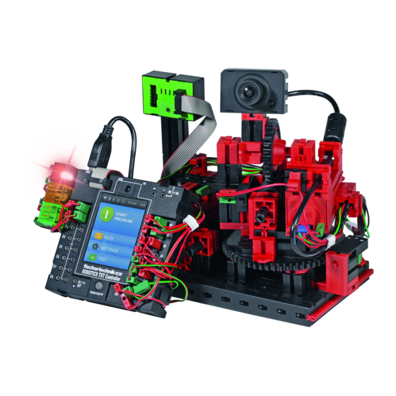
Page 37: Sensor Station With Movable Camera
ROBOTICS Smart Home Robotics Sensor Station IoT Sensor Station with Movable Camera This model uses various forms of data transmission. ▯ Connection via USB cable. ▯ Wireless via WiFi “Computer — TXT-Controller” (Access Point) ▯ Wireless via WiFi “Computer – Router – TXT-Controller” (WiFi Client) Construct the model as described in the assembly instructions and wire it accordingly. - Page 38 ROBOTICS Smart Home Robotics Sensor Station IoT Then drag the camera display into the control field. It is displayed with a certain size. if you want a larger image, click on the display with the mouse. It is then framed in red. Select “Draw”...
- Page 39 ROBOTICS Smart Home Robotics Sensor Station IoT The next thing you will want to do is control the model via WiFi. The method for creating the connection “Computer – TXT-Controller” as an access point, is described in the instruction manual for the TXT Controller under “Connecting the TXT Controller to the PC via WiFi”.
- Page 40 ROBOTICS Smart Home Robotics Sensor Station IoT Now enter the “WPA2 address” on the number pad Confirm the entry with the check mark at the top right. The code is displayed with dots in the brackets. Use the arrow key at the top left to go back until you again reach the “WiFi Mode”...
- Page 41 ROBOTICS Smart Home Robotics Sensor Station IoT Test: Connect a pushbutton to your computer at I1. Open “Interface Test”. Press pushbutton I1. A check mark should appear at I1 on the interface monitor. Now that you have set up the data link, you can try it out. To do this place the model in a different room.
- Page 42 ROBOTICS Smart Home Robotics Sensor Station IoT Important: Since the camera is supposed to react to motion, you will have to change the sensor field over to “Motion” as in the project “Stationary Camera with Motion Environmental Sensor – Data Logging”. Add an oscilloscope window next to the Pushbutton and Camera Field.
-
Page 43: Cloud Computing
ROBOTICS Smart Home Robotics Sensor Station IoT Cloud Computing In the next chapter we want to show you how to work with a cloud. The objective is for you to control the “Sensor Station with Movable Camera” model via a cloud connection. But what does “Cloud”... - Page 44 Here you can register your personal access for the fischertechnik cloud. To do this first go to “Register” in the registration window and enter the required data. Ensure that you spell everything correctly. It is easiest when you jot down the data.
- Page 45 Next activate “Settings” on your TXT Controller and then activate “Cloud Client”. Connect your TXT Controller to the fischertechnik Cloud with “Settings / Network / Cloud Settings / New Pairing. If the TXT Controller is able to establish a connection to the cloud, a QR code and a pairing code appear.
- Page 46 ROBOTICS Smart Home Robotics Sensor Station IoT As an alternative, you can go to “Settings / Add Controller” on the fischertecnik cloud site and enter the pairing code manually. Your TXT Controller is now connected to the cloud. Select the application TXTSmartHome under ..
- Page 47 The figure shows the current dashboard with the camera image, camera control, a picture gallery and the temperature reading. The following features are available on the fischertechnik cloud: “Display window on dashboard for temperature, humidity, atmospheric pressure, air quality, brightness, camera image, camera control and gallery for snapshots (made with the camera).
- Page 48 Temperature less than 4°C (frost monitor), Humidity greater than 80% (mold monitor). The desired language can be set in the dashboard menu. We wish you a great deal of enjoyment working out the individual program features. Your fischertechnik team...
-
Page 49: Trouble Shooting
ROBOTICS Smart Home Robotics Sensor Station IoT Trouble Shooting Interface Test Once again here our advice: Check each individual component for proper function with the aid of the ROBO Pro interface tests. If things don't work right from the very start there is usually a simple reason. But, it is not always easy to find. -
Page 50: Short Circuits
You can also visit our web site on the Internet at http://www.fischertechnik.de. Our Service FAQ’s on this site offer very helpful answers to numerous questions. In addition, you can also become a member of the fischertechnik Fan Club at no charge.
Need help?
Do you have a question about the ROBOTICS TXT Smart Home and is the answer not in the manual?
Questions and answers