Table of Contents

Related Manuals for WinGD X92-B


Summary of Contents for WinGD X92-B
- Page 1 Operation Manual X92-B Issue 002 2021-11 Winterthur Gas & Diesel Ltd. Schützenstrasse 3 Tel. +41 (0)52 264 8844 Winterthur Gas & Diesel AG P.O. Box 414, 8401 Fax +41 (0)52 264 8866 Winterthur Gas & Diesel S.A. Winterthur, Switzerland www.wingd.com...
- Page 2 Information in this publication is subject to change without notice. NO LIABILITY, WHETHER DIRECT, INDIRECT, SPECIAL, INCIDENTAL OR CONSEQUENTIAL, IS ASSUMED WITH RESPECT TO THE INFORMATION CONTAINED HEREIN. THIS PUBLICATION IS INTENDED FOR INFORMATION PURPOSES ONLY. www.wingd.com...
-
Page 3: Table Of Contents
X92-B Operation Manual Table of contents Introduction Operation Manual - change record................18 Preface........................20 Technical documentation set..................22 Data module codes (descriptive data)...............24 Data module codes (procedural data)...............26 About this book......................28 About the engine.......................30 List of abbreviations....................34 Safety Safety precautions and safety guidelines..............40... - Page 4 X92-B Operation Manual Group 1 - Engine frame and bearings 5.1.1 Bedplate......................114 5.1.2 Main bearing....................116 5.1.3 Thrust bearing....................118 5.1.4 Monoblock column...................120 5.1.5 rod......................122 Group 2 - Cylinder 5.2.1 Cylinder liner....................124 5.2.2 Lubricating quill....................126 5.2.3 Piston rod gland....................128 5.2.4 Direct controlled injection valve...............130...
- Page 5 X92-B Operation Manual 5.7.1 Cylinder lubrication..................188 5.7.2 Integrated electrical balancer (iELBA).............190 Group 8 - Pipes 5.8.1 Exhaust waste gate..................196 Group 9 - Monitoring instruments 5.9.1 Crank angle sensor unit...................198 5.9.2 Water in oil monitor..................200 5.9.3 Oil mist detector....................202 Control system Engine control system WiCE...................206...
- Page 6 X92-B Operation Manual 8.16 Emergency stop the engine - general..............286 8.17 Emergency stop the engine..................288 8.18 Prepare the engine after stop - general..............290 8.19 Prepare the engine for standstill or for maintenance..........292 Service during operation Do an analysis of the system oil................298...
- Page 7 X92-B Operation Manual 11.1 Engine data......................416 11.2 List of usual values and safeguard settings - general..........418 11.3 List of usual values and safeguard settings.............422 11.4 Section views......................434 Operating media 12.1 General for operating media..................436 12.2 Compressed air.......................438 12.3 Scavenge air......................440 12.4...
- Page 8 X92-B Operation Manual Page left intentionally blank - 8 - Issue 002 2021-11 Winterthur Gas & Diesel Ltd.
- Page 9 X92-B Operation Manual List of tables Introduction Change record ..................... Data module codes (descriptive data) ............Data module codes (procedural data) ............List of abbreviations and acronyms ............. Design and function of systems LP SCR SYSTEM STATUS (MAIN PAGE) ..........
- Page 10 X92-B Operation Manual 10-16 Piston cooling oil temperature downstream of a piston is too high ..... 10-17 Piston cooling oil flow to a piston is not in the permitted range ....10-18 TC bearing oil temperature at a turbocharger outlet is too high ....
- Page 11 X92-B Operation Manual 10-58 Cylinder liner wall temperature is too high ..........10-59 A fuel pump actuator has a failure ............... 10-60 Power supply to the power supply box E85 has a failure ......10-61 Unwanted engine speed decrease ..............
- Page 12 X92-B Operation Manual Page left intentionally blank - 12 - Issue 002 2021-11 Winterthur Gas & Diesel Ltd.
- Page 13 X92-B Operation Manual List of illustrations Introduction Side view (generic) ..................Engine numbering (generic) ................ Design and function of the engine Pressure - volume diagram and schematic of the two-stroke diesel cycle .. Operating range ..................Tuning options ..................... Schematic diagram - Relation Speed/Power (FPP) ........
- Page 14 X92-B Operation Manual Monoblock column (generic) ............... Tie rod (generic) ..................Cylinder - cooling water outlet (generic) ............Lubricating quill (generic) ................Piston rod gland (generic) ................Starting valve (example) ................5-10 Exhaust valve (generic) ................5-11 Crankshaft (generic) ..................
- Page 15 X92-B Operation Manual iGPR - schematic diagram ................LDU-20 - overview ..................LDU-20 color display - general items ............iELBA Control ....................MCP page - MAIN locked ................MCP page - MAIN ..................MCP page - Open user parameters ............
- Page 16 X92-B Operation Manual 10-23 Turbocharger cut out procedure: Illustration 5 ........... 10-24 Allowed load during cylinder cut out ............Technical data 11-1 Operating range ..................11-2 Signal codes ....................Operating media 12-1 Viscosity / Temperature diagram ..............Attachments 13-1 Line codes ....................
- Page 17 X92-B Operation Manual 1 Introduction Operation Manual - change record................18 Preface........................20 Technical documentation set..................22 Data module codes (descriptive data)...............24 Data module codes (procedural data)...............26 About this book......................28 About the engine.......................30 List of abbreviations....................34 - 17 - Issue 002 2021-11 Winterthur Gas & Diesel Ltd.
-
Page 18: Operation Manual - Change Record
AA00-0000-00AAA-003A-A X92-B Operation Manual Operation Manual - change record Operation Manual - change record Tab 1-1 Change record New issue 002, 2021-11 - Rewritten introductory pages with additional explanations. - Updated safety precautions and safety guidelines. - Updated description of access to engine spaces. - Page 19 AA00-0000-00AAA-003A-A X92-B Operation Manual Operation Manual - change record Page left intentionally blank - 19 - Issue 002 2021-11 Winterthur Gas & Diesel Ltd.
-
Page 20: Preface
The data, instructions, graphics and illustrations etc in this manual are related to drawings from WinGD. These data relate to the date of issue of the manual (the year of the issue is shown on the title page and on the footer). All instructions, graphics and illustrations etc can change because of continuous new development and modifications. - Page 21 AA00-0000-00AAA-018A-A X92-B Operation Manual Preface Page left intentionally blank - 21 - Issue 002 2021-11 Winterthur Gas & Diesel Ltd.
-
Page 22: Technical Documentation Set
AA00-0000-00AAA-018B-A X92-B Operation Manual Technical documentation set Technical documentation set Because of the continuous development of the engine, the technical documentation for the engine changes and is regularly updated. The change record shows all changes. Important data and changes are given directly to the customer in the service bulletins. - Page 23 External supplier documentation The documentation from external suppliers gives data about the parts of the engine that are not supplied by WinGD, such as turbocharger, automatic filter or damper. Most of this documentation also contains data about spare parts. 1.3.5...
-
Page 24: Data Module Codes (Descriptive Data)
00 = applicable to all engines indepen- acters [0-9] dent of the number of cylinders; ## = ap- plicable only to engines with that specific number of cylinders. #### WinGD design group number 4 numeric char- arbitrary 5551 acters [0-9] Used for sequential numbering of data... - Page 25 AA00-0000-00AAA-018D-A X92-B Operation Manual Data module codes (descriptive data) Page left intentionally blank - 25 - Issue 002 2021-11 Winterthur Gas & Diesel Ltd.
-
Page 26: Data Module Codes (Procedural Data)
00 = applicable to all engines indepen- acters [0-9] dent of the number of cylinders; ## = ap- plicable only to engines with that specific number of cylinders. #### WinGD design group number 4 numeric char- arbitrary 5556 acters [0-9] Used for sequential numbering for the... - Page 27 AA00-0000-00AAA-018E-A X92-B Operation Manual Data module codes (procedural data) Code Description Length/type Property Example Shipdex item location code. A = informa- 1 alphabetic Shipdex specif- tion related to items installed on the character [A-D] product; B = information related to items installed on a major assembly removed from the product;...
-
Page 28: About This Book
X92-B Operation Manual About this book About this book In the sections that follow you find the definitions of WinGD for this book. 1.6.1 Definitions for general text For general text in this book the definitions that follow are applicable: •... - Page 29 AA00-0000-00AAA-018C-A X92-B Operation Manual About this book 1.6.2 Warnings Warnings in procedures give data about a hazard. Warnings have the basic structure that follows: Signal word • The signal words that follow are applicable: ○ WARNING ○ CAUTION Hazard •...
-
Page 30: About The Engine
Operation Manual About the engine About the engine In the sections that follow you find the definitions of WinGD for the engine. 1.7.1 Groups of components Each component of the engine has a four-digit material number. WinGD has divided these... -
Page 31: Side View (Generic)
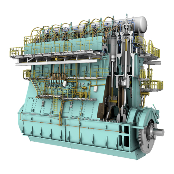
AA00-0000-00AAA-018L-A X92-B Operation Manual About the engine 1.7.2 Engine sides and ends - names The sides and ends of the engine have the names and abbreviations that follow (refer to Figure 1-1: DE - Driving End (end that has a flange to attach the propeller shaft) •... -
Page 32: Engine Numbering (Generic)
LEFT engine. Parts that are applicable for the two engines types (Standard and LEFT) have no mark. 1.7.4 Numbering of items WinGD uses the definitions for the numbering of items as follows (refer to Figure 1-2): In axial direction the numbering starts from the flywheel. - Page 33 AA00-0000-00AAA-018L-A X92-B Operation Manual About the engine Page left intentionally blank - 33 - Issue 002 2021-11 Winterthur Gas & Diesel Ltd.
-
Page 34: List Of Abbreviations
AA00-0000-00AAA-005A-A X92-B Operation Manual List of abbreviations List of abbreviations Tab 1-4 List of abbreviations and acronyms Short form Full form, meaning Angle Calculation Module crank Angle Determination Algorithm ahead alarm Alarm and Monitoring System as required astern ASTM American Society for Testing and Materials... - Page 35 AA00-0000-00AAA-005A-A X92-B Operation Manual List of abbreviations Short form Full form, meaning Emission Control Area Engine Control Room Engine Control System eg or e.g. for example (exempli gratia) Exhaust Gas Recirculation ELBA ELectrical BAlancer Exhaust Side Engine Safety System FAME...
- Page 36 AA00-0000-00AAA-005A-A X92-B Operation Manual List of abbreviations Short form Full form, meaning Injection Control Unit ie or i.e. that is (id est) iELBA integrated ELectrical BAlancer iGPR integrated Gas Pressure Regulation International Maritime Organization Ind. Indenture Input Output Module International Standard Organization...
- Page 37 Top Dead Center UNIC UNIfied Controls Universal Serial Bus exhaust Valve Control Unit Variable Exhaust valve Closing Variable Exhaust valve Opening Variable Injection Timing WECS-9520 WinGD Engine Control System 9520 - 37 - Issue 002 2021-11 Winterthur Gas & Diesel Ltd.
- Page 38 AA00-0000-00AAA-005A-A X92-B Operation Manual List of abbreviations Short form Full form, meaning Waste Heat Recovery WiCE WinGD Integrated Control Electronics WinGD Winterthur Gas & Diesel Ltd. Work Load Limit - 38 - Issue 002 2021-11 Winterthur Gas & Diesel Ltd.
-
Page 39: Safety
X92-B Operation Manual 2 Safety Safety precautions and safety guidelines..............40 Contamination and fire in the scavenge air spaces...........46 Fire-fighting in the scavenge air space..............48 Explosions in the crankcase..................50 Prevent explosions in the crankcase.................52 Access to engine spaces...................54 - 39 - Issue 002 2021-11 Winterthur Gas &... -
Page 40: Safety Precautions And Safety Guidelines
AA00-0000-00AAA-012A-A X92-B Operation Manual Safety precautions and safety guidelines Safety precautions and safety guidelines 2.1.1 General safety precautions The aim of this book is to give correct information about operation and maintenance of the engine. It is important to take the maximum safety in the engine room. All the engine room staff must follow these general safety precautions and safety guidelines given below as usual procedure. - Page 41 AA00-0000-00AAA-012A-A X92-B Operation Manual Safety precautions and safety guidelines Tools • Make sure that hand tools are available on tool panels and easy to access when required. Keep the special tools near the work area in the engine room. Make sure that all tools have protection from corrosion.
- Page 42 AA00-0000-00AAA-012A-A X92-B Operation Manual Safety precautions and safety guidelines Turning Gear and Slow turning • Before you engage the turning gear, make sure that the starting air supply is shutoff and the indicator cocks are open. When turning gear is engage, make sure that the indicator lamp “Turning gear in” is change to local.
- Page 43 AA00-0000-00AAA-012A-A X92-B Operation Manual Safety precautions and safety guidelines WARNING Injury hazard: The removal of fuel valves or other valves in the cylinder cover can cause the oil to fall on the piston crown. If the piston is hot this can cause explosion. Make sure that the engine is cool down before maintenance.
- Page 44 AA00-0000-00AAA-012A-A X92-B Operation Manual Safety precautions and safety guidelines Work card • Cotton boiler suite. • • Safety shoes. Hand gloves. • Safety goggles. • Safety harness • 2.1.5 General safety guidelines for Hot work If you do hot work at or near the engine, obey the guidelines that follow to prevent risks of harm or damage to personal, to equipment, or to environment.
- Page 45 AA00-0000-00AAA-012A-A X92-B Operation Manual Safety precautions and safety guidelines Guidelines for hot work: inside the engine room • Stop the engine before proceed any hot work in the engine room. Set the engine room fire extinguisher to Manual mode. Isolate the work area.
-
Page 46: Contamination And Fire In The Scavenge Air Spaces
AA00-0000-00AAA-012B-A X92-B Operation Manual Contamination and fire in the scavenge air spaces Contamination and fire in the scavenge air spaces 2.2.1 Causes of contamination The primary cause of contamination is when combustion materials are blown between the piston and cylinder into the scavenge air spaces (blow-by). The contamination will be more if the fuel is not fully burned, which causes exhaust smoke. - Page 47 AA00-0000-00AAA-012B-A X92-B Operation Manual Contamination and fire in the scavenge air spaces 2.2.2 Causes of fire The causes of fires are as follows: If sealing rings of the piston rod gland are defective, system oil and cylinder oil will collect •...
-
Page 48: Fire-Fighting In The Scavenge Air Space
AA00-0000-00AAA-140B-A X92-B Operation Manual Fire-fighting in the scavenge air space Fire-fighting in the scavenge air space Periodicity Description Unscheduled Duration for performing preliminary requirements 0.0 man-hours Duration for performing the procedure 1.0 man-hours Duration for performing the requirements after job completion 0.0 man-hours... - Page 49 AA00-0000-00AAA-140B-A X92-B Operation Manual Fire-fighting in the scavenge air space PROCEDURE If you think there is no fire, do the steps as follows: Decrease the engine power. Cut out the injection of the related cylinder. Increase the feed rate of the lubricating oil in the related cylinder to the maximum, although there is high temperature in the related cylinder.
-
Page 50: Explosions In The Crankcase
AA00-0000-00AAA-012C-A X92-B Operation Manual Explosions in the crankcase Explosions in the crankcase Examples of explosions in the crankcase of diesel engines have shown that they can only occur in special conditions, and thus do not occur frequently. The cause of crankcase explosions is oil mist. Oil mist comes from components that have become unusually hot. - Page 51 AA00-0000-00AAA-012C-A X92-B Operation Manual Explosions in the crankcase Page left intentionally blank - 51 - Issue 002 2021-11 Winterthur Gas & Diesel Ltd.
-
Page 52: Prevent Explosions In The Crankcase
AA00-0000-00AAA-012D-A X92-B Operation Manual Prevent explosions in the crankcase Prevent explosions in the crankcase Periodicity Description Unscheduled Duration for performing preliminary requirements 0.0 man-hours Duration for performing the procedure 1.0 man-hours Duration for performing the requirements after job completion 0.0 man-hours... - Page 53 AA00-0000-00AAA-012D-A X92-B Operation Manual Prevent explosions in the crankcase PROCEDURE If an oil mist detector activates an alarm, do as follows: Decrease immediately the engine speed (power). Stop the engine if possible. Let the engine temperature decrease for a minimum of 20 minutes.
-
Page 54: Access To Engine Spaces
AA00-0000-00AAA-012E-A X92-B Operation Manual Access to engine spaces Access to engine spaces Periodicity Description Unscheduled Duration for performing preliminary requirements 0.0 man-hours Duration for performing the procedure 0.5 man-hours Duration for performing the requirements after job completion 0.0 man-hours Personnel... - Page 55 AA00-0000-00AAA-012E-A X92-B Operation Manual Access to engine spaces PROCEDURE Make sure that there is always a safety person on the outer side of the engine. Use the correct personal protection equipments. For a DF engine, obey the safety rules for natural gas, refer to section...
- Page 56 AA00-0000-00AAA-012E-A X92-B Operation Manual Access to engine spaces Page left intentionally blank - 56 - Issue 002 2021-11 Winterthur Gas & Diesel Ltd.
-
Page 57: Design And Function Of The Engine
X92-B Operation Manual 3 Design and function of the engine Short description of the engine..................58 Use of the engine......................60 The relation between engine and propeller...............64 - 57 - Issue 002 2021-11 Winterthur Gas & Diesel Ltd. -
Page 58: Short Description Of The Engine
The engine control system (ECS) electronically controls all important engine functions (eg • speed control, overspeed protection and fuel injection). The engine control can have different remote controls, which are related to the WinGD specifications from recommended manufacturers. - 58 - Issue 002 2021-11 Winterthur Gas &... -
Page 59: Pressure - Volume Diagram And Schematic Of The Two-Stroke Diesel Cycle
AA00-0000-00AAA-020A-A X92-B Operation Manual Short description of the engine 3.1.1 Cycle of a two-stroke diesel engine The sequences of a two-stroke diesel engine are as follows (refer to Figure 3-1): Sequence 1 - 2 • The piston moves up and thus compresses the scavenge air. This increases the temperature of the air above the self-ignition temperature of the fuel. -
Page 60: Use Of The Engine
AA00-0000-00AAA-020C-A X92-B Operation Manual Use of the engine Use of the engine 3.2.1 Intended use The engine is intended to drive a propeller of a vessel. The engine changes the chemical energy of the fuel to mechanical energy. The engine must only be used in the operating range as given in the data sheets, refer to chapter 11. - Page 61 AA00-0000-00AAA-020C-A X92-B Operation Manual Use of the engine 3.2.2 Incorrect use Incorrect use of the engine can result in personal injury and in damage to physical properties. Personal injury or damage to physical properties caused by incorrect use will be the responsibility of the operating company.
-
Page 62: Tuning Options
AA00-0000-00AAA-020C-A X92-B Operation Manual Use of the engine 3.2.3 Tuning Related to the contract the engine has one of the tuning options that follow (refer to Figure 3-3): Standard tuning • The standard tuning gives a good fuel consumption over the full engine power range. - Page 63 AA00-0000-00AAA-020C-A X92-B Operation Manual Use of the engine Page left intentionally blank - 63 - Issue 002 2021-11 Winterthur Gas & Diesel Ltd.
-
Page 64: The Relation Between Engine And Propeller
AA00-0000-00AAA-042B-A X92-B Operation Manual The relation between engine and propeller The relation between engine and propeller 3.3.1 General There is a specified relation between the propeller speed and the absorbed power in ships that have fixed pitch propellers. The relation is between the propeller and the speed at which it turns. -
Page 65: Schematic Diagram - Relation Speed/Power (Fpp)
AA00-0000-00AAA-042B-A X92-B Operation Manual The relation between engine and propeller 3.3.2 Fixed pitch propeller (FPP) 3.3.2.1 Continuous service rating Point A (Figure 3-4) shows the power and speed of a ship that operates at contractual speed in calm seas with a new clean hull and propeller. A power / speed combination at point D is necessary for the same ship at the same speed during service conditions with aged hull and average weather. -
Page 66: Operation
AA00-0000-00AAA-042B-A X92-B Operation Manual The relation between engine and propeller Line 2 is the overload limit. This is a constant MEP line from 100% power and 93.8% speed • to 110% power and 103.2% speed. 103.2% speed is the intersection point between the nominal propeller property and 110% power. -
Page 67: Design And Function Of Systems
X92-B Operation Manual 4 Design and function of systems General for systems....................68 Cooling water system....................70 Wash-water system....................72 System oil system......................74 Servo oil system......................76 Cylinder oil system....................78 Starting air system.....................80 Scavenge air system....................82 Control air system......................84 4.10 Exhaust gas system....................86 4.11 Fuel system.......................88... -
Page 68: General For Systems
AA00-0000-00AAA-043U-A X92-B Operation Manual General for systems General for systems In the chapters that follow you can find a short description of the systems of the engine. The descriptions and figures are generic and simplified. You can find an overview of the used line codes in Figure 4-1. - Page 69 AA00-0000-00AAA-043U-A X92-B Operation Manual General for systems Page left intentionally blank - 69 - Issue 002 2021-11 Winterthur Gas & Diesel Ltd.
-
Page 70: Cooling Water System
AA00-0000-00AAA-043A-A X92-B Operation Manual Cooling water system Cooling water system The cooling water system supplies the items that follow with cooling water: Cylinder liner • Cylinder cover • Exhaust valve cages • • Scavenge air cooler (SAC). For the schematic diagrams, refer to section 13.1 Schematic diagrams -... -
Page 71: Cooling Water System (Generic And Simplified)
AA00-0000-00AAA-043A-A X92-B Operation Manual Cooling water system Fig 4-2 Cooling water system (generic and simplified) Cyl. 1 Cyl. n Legend Automatic venting unit Drain valve Shut-off valve cooling water outlet Orifice Shut-off valve, if supply 02 is installed Optional vent valve (usually closed) -
Page 72: Wash-Water System
AA00-0000-00AAA-043P-A X92-B Operation Manual Wash-water system Wash-water system The wash-water system supplies the scavenge air cooler (SAC) with wash-water. This lets you wash the SAC, refer to 9.5 Clean the scavenge air cooler during operation. To regularly wash the SAC increases the service life of the cooler and keeps the performance in the specified range. - Page 73 AA00-0000-00AAA-043P-A X92-B Operation Manual Wash-water system Fig 4-3 Wash-water system (generic and simplified) 11 12 Legend Wash-water tank Cyclone separator Scavenge air cooler (SAC) Turbocharger Auxiliary blower - 73 - Issue 002 2021-11 Winterthur Gas & Diesel Ltd.
-
Page 74: System Oil System
AA00-0000-00AAA-043B-A X92-B Operation Manual System oil system System oil system The system oil system supplies the items that follow with system oil: Bearings • Gear wheels • Vibration dampers • • Pistons Crosshead assemblies • iELBA (optional) • Other running parts •... -
Page 75: System Oil System (Generic And Simplified)
AA00-0000-00AAA-043B-A X92-B Operation Manual System oil system Fig 4-4 System oil system (generic and simplified) PLANT ENGINE ENGINE PLANT 23 22 22 23 Legend Turbocharger Crosshead iELBA (optional) Thrust bearing Torsional vibration damper (optional) Oil sample valve Axial vibration damper... -
Page 76: Servo Oil System
AA00-0000-00AAA-043Q-A X92-B Operation Manual Servo oil system Servo oil system The servo oil system supplies the items that follow with servo oil: Exhaust valve control units (VCU) • Cylinder lubricating pumps • Injection control units, if applicable. • For the schematic diagrams, refer to section 13.1 Schematic diagrams -... -
Page 77: Servo Oil System (Generic And Simplified)
AA00-0000-00AAA-043Q-A X92-B Operation Manual Servo oil system Fig 4-5 Servo oil system (generic and simplified) Cyl. 1 Cyl. 2 Cyl. n Legend Injection control unit (ICU) for X82 and X92 Oil pipe to exhaust valve Exhaust valve control unit (VCU) -
Page 78: Cylinder Oil System
AA00-0000-00AAA-043R-A X92-B Operation Manual Cylinder oil system Cylinder oil system The cylinder oil system supplies cylinder oil onto the cylinder liners. The engine control system (ECS) controls the adjustable load-related supply rate of cylinder oil to each lubrication point. The engine has an automatic pre-lubrication sequence. At each engine start the ECS automatically starts this sequence. -
Page 79: Cylinder Oil System (Generic And Simplified, With And Without Icat)
AA00-0000-00AAA-043R-A X92-B Operation Manual Cylinder oil system Fig 4-6 Cylinder oil system (generic and simplified, with and without iCAT) iCAT Cyl. 1 Cyl. n Legend Oil sample valve Square collector pipe Lubricating quill Rail unit Cylinder lubricating pump Change-over valve... -
Page 80: Starting Air System
AA00-0000-00AAA-043C-A X92-B Operation Manual Starting air system Starting air system The starting air system turns the crankshaft before the usual combustion cycle of the engine is started. For the schematic diagrams, refer to section 13.1 Schematic diagrams - general. The starting air system has the engine connections as interface to the plant as follows (in... -
Page 81: Starting Air System (Generic And Simplified)
AA00-0000-00AAA-043C-A X92-B Operation Manual Starting air system Fig 4-7 Starting air system (generic and simplified) Cyl. 1 Cyl. n Legend Solenoid valve Disengaging device turning gear Flame arrestor Starting air supply pipe Safety valve Valve unit for start E Drain valve... -
Page 82: Scavenge Air System
AA00-0000-00AAA-043S-A X92-B Operation Manual Scavenge air system Scavenge air system The scavenge air system replaces the exhaust gas in the cylinder with fresh air. For the schematic diagrams, refer to section 13.1 Schematic diagrams - general. The scavenge air comes in from the outside through a duct or from the engine room. The scavenge air enters at the silencer of the turbocharger. - Page 83 AA00-0000-00AAA-043S-A X92-B Operation Manual Scavenge air system Fig 4-8 Scavenge air system 00148 Legend Exhaust gas manifold Drains Exhaust gas outlet Auxiliary blower Scavenge air inlet Piston underside Turbine Piston Compressor Scavenge air receiver Scavenge air cooler Cylinder liner Water separator...
-
Page 84: Control Air System
AA00-0000-00AAA-043T-A X92-B Operation Manual Control air system Control air system The control air system supplies the air spring of the exhaust valves and the starting air system with control air. For the schematic diagrams, refer to section 13.1 Schematic diagrams - general. -
Page 85: Control Air System (Generic And Simplified)
AA00-0000-00AAA-043T-A X92-B Operation Manual Control air system Fig 4-9 Control air system (generic and simplified) Cyl. 1 Cyl. n Legend Air bottle Starting air shut-off valve Control air supply Valve unit for start Air tank Collector for leakage oil from the air spring... -
Page 86: Exhaust Gas System
AA00-0000-00AAA-043D-A X92-B Operation Manual Exhaust gas system 4.10 Exhaust gas system The exhaust gas system collects the exhaust gas of the cylinders in a manifold. The remaining energy of the exhaust gas is used to operate the turbine of the turbocharger (002,... - Page 87 AA00-0000-00AAA-043D-A X92-B Operation Manual Exhaust gas system Fig 4-10 Exhaust gas system (generic and simplified) Cyl. 1 Cyl. 2 Cyl. 3 Cyl. 4 Cyl. n Legend Turbocharger bypass pipe Exhaust gas manifold Turbocharger Exhaust valve - 87 - Issue 002 2021-11...
-
Page 88: Fuel System
AA00-0000-00AAA-043E-A X92-B Operation Manual Fuel system 4.11 Fuel system The fuel system supplies the injection valves of the cylinders with the applicable quantity of fuel. For the schematic diagrams, refer to section 13.1 Schematic diagrams - general. The fuel system has the engine connections as interface to the plant as follows (in... - Page 89 AA00-0000-00AAA-043E-A X92-B Operation Manual Fuel system Pressure control valve • The pressure control valve (001) has different functions to control the flow and the pressure in the fuel rail. Relief valve • The relief valve (002) is a safety device. If the fuel pressure increases to more than the set value, the relief valve opens.
-
Page 90: Fuel System With Flv (Generic And Simplified)
AA00-0000-00AAA-043E-A X92-B Operation Manual Fuel system Fig 4-11 Fuel system with FLV (generic and simplified) Cyl. 1 Cyl. n Legend Pressure control valve Injection valve Relief valve Supply unit Flow limiting valve (FLV) Fuel pump Fuel rail Pressure retaining valve... -
Page 91: Fuel System With Icu (Generic And Simplified)
AA00-0000-00AAA-043E-A X92-B Operation Manual Fuel system Fig 4-12 Fuel system with ICU (generic and simplified) Cyl. 1 Cyl. 2 Cyl. 3 Cyl. 4 Cyl. n 60 50 49 Legend Pressure control valve Injection valve Relief valve Supply unit Injection control unit (ICU) -
Page 92: Lp Selective Catalytic Reduction System
The LP SCR system is installed after the turbocharger. The system design and the supply of components is divided between the LP SCR system supplier, the shipyard and WinGD/engine builder. The LP SCR system adds a urea water solution to the exhaust gas flow. Chemical reactions change nitrogen oxides to molecular nitrogen and water, which are not dangerous. -
Page 93: Lp Scr Temperature Controlled (Example)
AA00-9270-00AAA-043B-A X92-B Operation Manual LP Selective catalytic reduction system Valves • The valves in the LP SCR system are used for the different operation modes. The LP SCR system has the valves that follow: ○ V1 - reactor inlet valve ○... -
Page 94: Lp Scr Bypass Rate Controlled (Example)
AA00-9270-00AAA-043B-A X92-B Operation Manual LP Selective catalytic reduction system Fig 4-14 LP SCR bypass rate controlled (example) 002 003 Legend Engine Burner Urea dosing unit LP SCR reactor Decomposition unit Turbocharger 4.12.2 Operation modes The LP SCR system can be operated if the exhaust gas temperature is in the permitted limits. - Page 95 AA00-9270-00AAA-043B-A X92-B Operation Manual LP Selective catalytic reduction system 4.12.2.2 LP SCR system - preparation In this operation mode, exhaust gas causes the temperature of the LP SCR reactor to slowly increase. Urea solution is not injected. The valves have the conditions that follow: •...
-
Page 96: Lp Scr Control System Layout
LP Selective catalytic reduction system 4.12.3 LP SCR control system The main tasks of the WinGD control system for the LP SCR system are as follows: Calculate the setpoint position for the turbine bypass valve (V4) to control the exhaust gas •... -
Page 97: Lp Scr System - Principal Control Configuration
AA00-9270-00AAA-043B-A X92-B Operation Manual LP Selective catalytic reduction system Fig 4-16 LP SCR system - principal control configuration Engine room Signals External main control panel (E73) 4.12.3.1 Messages of the LP SCR control system The LP SCR control system gives three messages to the alarm and monitoring system (AMS). -
Page 98: Control Box E70 With Option Spc
AA00-9270-00AAA-043B-A X92-B Operation Manual LP Selective catalytic reduction system 4.12.3.2 Control box E70 The control box E70 is installed on the engine and has switches and visual indicators. Fig 4-17 Control box E70 with option SPC Legend SCR bypass switch... -
Page 99: Control Box E71 With Option Spc
AA00-9270-00AAA-043B-A X92-B Operation Manual LP Selective catalytic reduction system 4.12.3.3 Control box E71 The control box E71 is installed on the engine or in the engine room and has switches below the LDU-20. Fig 4-18 Control box E71 with option SPC... -
Page 100: Control Boxes E72 And E73
AA00-9270-00AAA-043B-A X92-B Operation Manual LP Selective catalytic reduction system 4.12.3.4 Control box E72 or E73 The control box E72 (without SPC) or E73 (with SPC) is installed in the engine control room and has switches below the LDU-20. Fig 4-19... -
Page 101: Lp Scr System Status (Main Page)
AA00-9270-00AAA-043B-A X92-B Operation Manual LP Selective catalytic reduction system 4.12.4 LDU-20 pages The LDU-20 panel has the pages that follow (examples). Fig 4-20 LDU-20 page - LP SCR SYSTEM STATUS (MAIN PAGE) Tab 4-1 LP SCR SYSTEM STATUS (MAIN PAGE) -
Page 102: Lp Scr System Overview
AA00-9270-00AAA-043B-A X92-B Operation Manual LP Selective catalytic reduction system Fig 4-21 LDU-20 page - LP SCR SYSTEM OVERVIEW Tab 4-2 LP SCR SYSTEM OVERVIEW Item Function Effect INTERFACES button Opens the interfaces page INDEX button Opens the index page SCREENSHOT button... -
Page 103: Lp Scr Interfaces
AA00-9270-00AAA-043B-A X92-B Operation Manual LP Selective catalytic reduction system Fig 4-22 LDU-20 page - LP SCR INTERFACES Tab 4-3 LP SCR INTERFACES Item Function Effect OVERVIEW button Opens the SCR system overview page INDEX button Opens the index page SCREENSHOT button... -
Page 104: Lp Scr Software Info
AA00-9270-00AAA-043B-A X92-B Operation Manual LP Selective catalytic reduction system Fig 4-23 LDU-20 page - LP SCR SOFTWARE INFO Tab 4-4 LP SCR SOFTWARE INFO Item Function Effect INDEX button Opens the index page SCREENSHOT button Makes a screenshot of the current screen... -
Page 105: Lp Scr Page Index
AA00-9270-00AAA-043B-A X92-B Operation Manual LP Selective catalytic reduction system Fig 4-24 LDU-20 page - LP SCR PAGE INDEX Tab 4-5 LP SCR PAGE INDEX Item Function Effect INDEX button Opens the index page SCREENSHOT button Makes a screenshot of the current screen... -
Page 106: Steam Production Control System
AA00-9270-00AAA-043C-A X92-B Operation Manual Steam production control system 4.13 Steam production control system The steam production control system (SPC) supplies the steam production of the ship with exhaust gas, which has a higher temperature. SPC is an optional system. NOTE: The engine obeys the IMO NOx limits, with and without steam production. -
Page 107: Ldu-20 Page - Steam Production Control
AA00-9270-00AAA-043C-A X92-B Operation Manual Steam production control system Fig 4-26 LDU-20 page - STEAM PRODUCTION CONTROL Tab 4-6 STEAM PRODUCTION CONTROL (SPC) Item Function Effect ON/OFF button Starts or stops the SPC system INDEX button Opens the index page SCREENSHOT button... - Page 108 AA00-9270-00AAA-043C-A X92-B Operation Manual Steam production control system Item Function Effect PressCtrl mode 1 button Starts the PressCtrl mode 1 This mode is applicable only, if the steam pressure signal from the steam plant is correct. SPC compares the setpoint and the actual steam pressure. If there is a difference, it opens or closes the EWG to change the steam pressure.
-
Page 109: Ldu For The Steam Boost Mode
AA00-9270-00AAA-043C-A X92-B Operation Manual Steam production control system 4.13.4 LDU screen for steam boost mode Fig 4-27 LDU for the steam boost mode - 109 - Issue 002 2021-11 Winterthur Gas & Diesel Ltd. - Page 110 AA00-9270-00AAA-043C-A X92-B Operation Manual Steam production control system 4.13.5 Activate the steam boost mode Before activating the steam boost mode, make sure the LDU-Screen (Figure 4-27) shows the following: Firing Pressure Gas Mode indicates (5) “OK”. • Servo Oil (6) indicates “OK”.
-
Page 111: Design And Function Of Components
X92-B Operation Manual 5 Design and function of components Group 1 - Engine frame and bearings 5.1.1 Bedplate......................114 5.1.2 Main bearing....................116 5.1.3 Thrust bearing....................118 5.1.4 Monoblock column...................120 5.1.5 rod......................122 Group 2 - Cylinder 5.2.1 Cylinder liner....................124 5.2.2 Lubricating quill....................126 5.2.3 Piston rod gland....................128... - Page 112 X92-B Operation Manual 5.6.5 Scavenge air cooler..................184 5.6.6 Water separator....................186 Group 7 - Cylinder lubrication and balancer 5.7.1 Cylinder lubrication..................188 5.7.2 Integrated electrical balancer (iELBA).............190 Group 8 - Pipes 5.8.1 Exhaust waste gate..................196 Group 9 - Monitoring instruments 5.9.1 Crank angle sensor unit...................198...
- Page 113 X92-B Operation Manual Page left intentionally blank - 113 - Issue 002 2021-11 Winterthur Gas & Diesel Ltd.
-
Page 114: Group 1 - Engine Frame And Bearings Bedplate
AA00-1115-00AAA-043A-A X92-B Operation Manual Bedplate Group 1 - Engine frame and bearings 5.1.1 Bedplate The bedplate is the basic structure of the engine. The bearing girders (001, Figure 5-1) are attached in the bedplate and hold the crankshaft. The bottom part of the bedplate is the crankcase and collects lubricating oil. This oil flows back to the oil supply system through oil drains (002). - Page 115 AA00-1115-00AAA-043A-A X92-B Operation Manual Bedplate Page left intentionally blank - 115 - Issue 002 2021-11 Winterthur Gas & Diesel Ltd.
-
Page 116: Main Bearing
AA00-1132-00AAA-043A-A X92-B Operation Manual Main bearing 5.1.2 Main bearing The main bearings hold the crankshaft (007, Figure 5-2) and transmit the forces through the bearing girders (008) into the bedplate. The bottom bearing shell (006) is installed in the bearing girder (008) of the bedplate and the top bearing shell (004) in the bearing cover (003). - Page 117 AA00-1132-00AAA-043A-A X92-B Operation Manual Main bearing Page left intentionally blank - 117 - Issue 002 2021-11 Winterthur Gas & Diesel Ltd.
-
Page 118: Thrust Bearing
AA00-1203-00AAA-043A-A X92-B Operation Manual Thrust bearing 5.1.3 Thrust bearing The thrust bearing is installed on the crankshaft at the driving end of the engine. The thrust bearing flange (014, Figure 5-3) transmits the axial thrust from the propeller through the thrust pads into the bedplate: •... -
Page 119: Thrust Bearing (Generic)
AA00-1203-00AAA-043A-A X92-B Operation Manual Thrust bearing Fig 5-3 Thrust bearing (generic) Legend Column Crankshaft Oil pipe 2-part oil baffle Nozzle Flywheel Arbor support Bedplate Bedplate Thrust pad (engine side) Thrust pad (driving end) Thrust bearing flange Bearing cover Column Crankshaft gear wheel... -
Page 120: Monoblock Column
AA00-1406-00AAA-043A-A X92-B Operation Manual Monoblock column 5.1.4 Monoblock column The monoblock column is the middle part of the engine. The monoblock column is installed on the bedplate and holds the cylinders. On the exhaust side (ES) the monoblock column has one relief valve (001, Figure 5-4) per cylinder. - Page 121 AA00-1406-00AAA-043A-A X92-B Operation Manual Monoblock column Page left intentionally blank - 121 - Issue 002 2021-11 Winterthur Gas & Diesel Ltd.
-
Page 122: Tie Rod
AA00-1903-00AAA-043A-A X92-B Operation Manual Tie rod 5.1.5 Tie rod The tie rods (004, Figure 5-5) keep the cylinder block (002), column (003) and bedplate (005) together at four locations around each cylinder. Fig 5-5 Tie rod (generic) Legend Protection cover... - Page 123 AA00-1903-00AAA-043A-A X92-B Operation Manual Tie rod Page left intentionally blank - 123 - Issue 002 2021-11 Winterthur Gas & Diesel Ltd.
-
Page 124: Group 2 - Cylinder Cylinder Liner
AA00-2124-00AAA-043A-A X92-B Operation Manual Cylinder liner Group 2 - Cylinder 5.2.1 Cylinder liner The cylinder liner is one of the primary parts of the engine. The cylinder liner is on the cylinder jacket and holds the cylinder cover and the water guide jackets. The nuts and the elastic bolts hold these parts together. - Page 125 AA00-2124-00AAA-043A-A X92-B Operation Manual Cylinder liner Page left intentionally blank - 125 - Issue 002 2021-11 Winterthur Gas & Diesel Ltd.
-
Page 126: Lubricating Quill
AA00-2138-00AAA-043A-A X92-B Operation Manual Lubricating quill 5.2.2 Lubricating quill The lubricating quills spray oil onto the cylinder liner wall. The lubricating quills are installed on the circumference of the cylinder liner. The cylinder lubricating pump supplies a specified quantity of cylinder oil at high pressure through... - Page 127 AA00-2138-00AAA-043A-A X92-B Operation Manual Lubricating quill Page left intentionally blank - 127 - Issue 002 2021-11 Winterthur Gas & Diesel Ltd.
-
Page 128: Piston Rod Gland
AA00-2303-00AAA-043A-A X92-B Operation Manual Piston rod gland 5.2.3 Piston rod gland The piston rod gland keeps the dirty cylinder oil in the scavenge space and thus prevents contamination of the bearing oil in the crankcase. Also, the piston rod gland seals the scavenge air from the crankcase. - Page 129 AA00-2303-00AAA-043A-A X92-B Operation Manual Piston rod gland Page left intentionally blank - 129 - Issue 002 2021-11 Winterthur Gas & Diesel Ltd.
-
Page 130: Direct Controlled Injection Valve
AA00-2722-00AAA-043A-A X92-B Operation Manual Direct controlled injection valve 5.2.4 Direct controlled injection valve The injection valves are installed in the cylinder cover of each cylinder. The injection valves spray the fuel into the combustion chamber. The ECS controls the pilot valve of the injection valves indirectly through the solenoid valve. - Page 131 AA00-2722-00AAA-043A-A X92-B Operation Manual Direct controlled injection valve Page left intentionally blank - 131 - Issue 002 2021-11 Winterthur Gas & Diesel Ltd.
-
Page 132: Starting Valve
AA00-2728-00AAA-043A-A X92-B Operation Manual Starting valve 5.2.5 Starting valve The starting valve in each cylinder cover supplies pressurized air into the combustion chamber in the two situations that follow: To start the engine before combustion starts • • To decrease the engine speed when combustion has stopped. - Page 133 AA00-2728-00AAA-043A-A X92-B Operation Manual Starting valve Page left intentionally blank - 133 - Issue 002 2021-11 Winterthur Gas & Diesel Ltd.
-
Page 134: Exhaust Valve
AA00-2751-00AAA-043A-A X92-B Operation Manual Exhaust valve 5.2.6 Exhaust valve The exhaust valve in each cylinder cover releases the exhaust gas of the combustion into the exhaust gas manifold. The hydraulic oil pressure from the exhaust valve control unit (VCU) opens the exhaust valve. - Page 135 AA00-2751-00AAA-043A-A X92-B Operation Manual Exhaust valve Air spring • When the exhaust valve is closed, compressed air flows through an air inlet connection into the air spring (011). When the exhaust valve opens, this air is compressed to a higher value.
-
Page 136: Group 3 - Crankshaft, Connecting Rod And Piston Crankshaft
AA00-3103-00AAA-043A-A X92-B Operation Manual Crankshaft Group 3 - Crankshaft, connecting rod and piston 5.3.1 Crankshaft The crankshaft turns as it gets the power from the pistons. The crankshaft transmits the power to the attached propeller shaft of the ship. Main bearings on the two sides of each crank (002, Figure 5-11) hold the crankshaft in position. - Page 137 AA00-3103-00AAA-043A-A X92-B Operation Manual Crankshaft Page left intentionally blank - 137 - Issue 002 2021-11 Winterthur Gas & Diesel Ltd.
-
Page 138: Torsional Vibration Damper
AA00-3130-00AAA-043A-A X92-B Operation Manual Torsional vibration damper 5.3.2 Torsional vibration damper The torsional vibration damper decreases the torsional vibrations in the shafting system and in other components of the engine. If a torsional vibration damper is necessary for the engine, one of the two damper types that follow can be used. - Page 139 AA00-3130-00AAA-043A-A X92-B Operation Manual Torsional vibration damper 5.3.2.1 Steel spring damper A steel spring damper (Figure 5-12) is a tuned torsional vibration damper. It consists of two main parts: The inner part (inner star (005) and spring pack (004)) is attached to the crankshaft flange •...
- Page 140 AA00-3130-00AAA-043A-A X92-B Operation Manual Torsional vibration damper 5.3.2.2 Viscous damper A viscous damper (Figure 5-13) is a tuned torsional vibration damper. It consists of two main parts: The housing (002) is fully sealed and is attached to the crankshaft flange at the free end.
- Page 141 AA00-3130-00AAA-043A-A X92-B Operation Manual Torsional vibration damper Page left intentionally blank - 141 - Issue 002 2021-11 Winterthur Gas & Diesel Ltd.
-
Page 142: Axial Vibration Damper
AA00-3140-00AAA-043A-A X92-B Operation Manual Axial vibration damper 5.3.3 Axial vibration damper The axial vibration damper decreases the axial vibrations of the crankshaft. The axial vibration damper is attached with bolts to the last bearing girder at the free end of the engine. - Page 143 AA00-3140-00AAA-043A-A X92-B Operation Manual Axial vibration damper 5.3.3.1 Function Oil flows from the oil inlet (012) through the top cylinder half (002) into the two annular spaces (003). When the crankshaft (004) moves in an axial direction, the pressure of the oil in the compressed annular space (003) increases.
-
Page 144: Turning Gear
AA00-3206-00AAA-043A-A X92-B Operation Manual Turning gear 5.3.4 Turning gear The turning gear slowly turns the crankshaft and thus moves the pistons, if the pinion (002, Figure 5-16) is engaged on the flywheel (003). The electric motor (001) turns the pinion (002) and is attached on the driving end of the engine. - Page 145 AA00-3206-00AAA-043A-A X92-B Operation Manual Turning gear Page left intentionally blank - 145 - Issue 002 2021-11 Winterthur Gas & Diesel Ltd.
-
Page 146: Connecting Rod And Connecting Rod Bearing
AA00-3303-00AAA-043A-A X92-B Operation Manual Connecting rod and connecting rod bearing 5.3.5 Connecting rod and connecting rod bearing The connecting rod connects the crosshead with the crankshaft and converts the linear movement of the piston into a circular movement of the crankshaft. - Page 147 AA00-3303-00AAA-043A-A X92-B Operation Manual Connecting rod and connecting rod bearing Page left intentionally blank - 147 - Issue 002 2021-11 Winterthur Gas & Diesel Ltd.
-
Page 148: Crosshead And Guide Shoe
AA00-3326-00AAA-043A-A X92-B Operation Manual Crosshead and guide shoe 5.3.6 Crosshead and guide shoe The crosshead guides the piston rod (009, Figure 5-18) and absorbs the lateral forces that come from the connecting rod (005). The piston rod (009) is attached to the compression shim (007) and the crosshead pin (006) with screws. - Page 149 AA00-3326-00AAA-043A-A X92-B Operation Manual Crosshead and guide shoe Page left intentionally blank - 149 - Issue 002 2021-11 Winterthur Gas & Diesel Ltd.
-
Page 150: Piston
AA00-3403-00AAA-043A-A X92-B Operation Manual Piston 5.3.7 Piston The piston moves in each cylinder. The piston rings seal the combustion chamber. The piston transmits the force from the gas that expands in the cylinder to the crankshaft through the connecting rod. - Page 151 AA00-3403-00AAA-043A-A X92-B Operation Manual Piston Page left intentionally blank - 151 - Issue 002 2021-11 Winterthur Gas & Diesel Ltd.
-
Page 152: Group 4 - Supply Unit Drive And Control Components Supply Unit Drive
AA00-4104-00AAA-043A-A X92-B Operation Manual Supply unit drive Group 4 - Supply unit drive and control components 5.4.1 Supply unit drive The supply unit drive is installed at the driving end of the engine on the fuel side. The crankshaft gear wheel (003, Figure 5-20) moves the intermediate wheel (001). - Page 153 AA00-4104-00AAA-043A-A X92-B Operation Manual Supply unit drive Fig 5-20 Supply unit drive (generic) Legend Intermediate wheel Gear wheel (servo oil pumps) Flywheel Intermediate wheel Crankshaft gear wheel Crankshaft Gear wheel (servo oil pump) - 153 - Issue 002 2021-11 Winterthur Gas & Diesel Ltd.
-
Page 154: Starting Air Shut-Off Valve
AA00-4325-00AAA-043A-A X92-B Operation Manual Starting air shut-off valve 5.4.2 Starting air shut-off valve The starting air shut-off valve supplies the starting air pipe with starting air. The starting air shut- off valve has a hand-wheel with three positions: CLOSED •... - Page 155 AA00-4325-00AAA-043A-A X92-B Operation Manual Starting air shut-off valve During the start sequence the MCM-20 / IOM-20 module operates the solenoid valves (014) and (016). The control air from the control air inlet (017) opens the control valve (001) through the solenoid valve CV7014C (014) and releases the pressure in the valve space (002).
-
Page 156: Control Air Supply
AA00-4605-00AAA-043A-A X92-B Operation Manual Control air supply 5.4.3 Control air supply The control air supply supplies control air to the engine. The plant supply systems supply compressed air with the specified properties at the two engine connections that follow: Connection 45 (control air supply inlet) for usual supply •... - Page 157 AA00-4605-00AAA-043A-A X92-B Operation Manual Control air supply Page left intentionally blank - 157 - Issue 002 2021-11 Winterthur Gas & Diesel Ltd.
-
Page 158: Local Maneuvering Stand For Unic
AA00-4618-00AAA-043A-A X92-B Operation Manual Local maneuvering stand for UNIC 5.4.4 Local maneuvering stand for UNIC The local maneuvering stand has the local control panel (001, Figure 5-23) and is attached to the engine at the free end. The local control panel has the components necessary for engine operation. - Page 159 AA00-4618-00AAA-043A-A X92-B Operation Manual Local maneuvering stand for UNIC 5.4.4.1 Local control panel NOTE: If a fault occurs in the remote control, which prevents engine control from the control room, you can operate the engine from the local control panel.
-
Page 160: Pick-Up For Speed Measurement
AA00-4628-00AAA-043A-A X92-B Operation Manual Pick-up for speed measurement 5.4.5 Pick-up for speed measurement To measure the engine speed (rpm), proximity sensors are installed in a speed pick-up unit, attached to the support near the flywheel. For safety, there are three electrically isolated proximity sensor groups as follows: Speed identification in the remote control system (RCS) •... - Page 161 AA00-4628-00AAA-043A-A X92-B Operation Manual Pick-up for speed measurement Page left intentionally blank - 161 - Issue 002 2021-11 Winterthur Gas & Diesel Ltd.
-
Page 162: Group 5 - Supply Unit, Pumps And Control Valves Servo Oil Pump
AA00-5551-00AAA-043A-A X92-B Operation Manual Servo oil pump Group 5 - Supply unit, pumps and control valves 5.5.1 Servo oil pump The servo oil pumps (004, Figure 5-25) supply the servo oil system with oil during usual operation. The number of servo oil pumps is related to the engine. - Page 163 AA00-5551-00AAA-043A-A X92-B Operation Manual Servo oil pump Page left intentionally blank - 163 - Issue 002 2021-11 Winterthur Gas & Diesel Ltd.
-
Page 164: Supply Unit
AA00-5552-00AAA-043A-A X92-B Operation Manual Supply unit 5.5.2 Supply unit The supply unit includes the servo oil pumps and the fuel pumps. The supply unit is installed on the column at the driving end of the engine. The gear wheels and intermediate wheels in the supply unit operate the fuel pumps and servo oil pumps, refer to section 5.4.1 Supply unit... - Page 165 AA00-5552-00AAA-043A-A X92-B Operation Manual Supply unit Page left intentionally blank - 165 - Issue 002 2021-11 Winterthur Gas & Diesel Ltd.
-
Page 166: Fuel Pump
AA00-5556-00AAA-043A-A X92-B Operation Manual Fuel pump 5.5.3 Fuel pump The fuel pumps (001, Figure 5-27) supply the fuel rail with fuel at high pressure. The number of fuel pumps is related to the engine. Fig 5-27 Fuel pump (generic) Legend... -
Page 167: Fuel Pump - Cross Section (Example)
AA00-5556-00AAA-043A-A X92-B Operation Manual Fuel pump Fig 5-28 Fuel pump - cross section (example) Legend HP fuel to fuel rail Guide piston Fuel inlet Driver (of pump plunger) Pump plunger Regulating sleeve Compression spring Toothed rack Bottom spring carrier Fuel outlet... -
Page 168: Pressure Control Valve
AA00-5562-00AAA-043A-A X92-B Operation Manual Pressure control valve 5.5.4 Pressure control valve The pressure control valve (PCV) (002, Figure 5-29) is attached to the fuel rail (007) and has the functions that follow: Usual operation • During usual operation the engine software controls the fuel flow and thus the fuel pressure. -
Page 169: Pressure Control Valve - Location (Example)
AA00-5562-00AAA-043A-A X92-B Operation Manual Pressure control valve Fig 5-29 Pressure control valve - location (example) Legend Solenoid valve (ZV7061S) Fuel return pipe Pressure control valve (10-5562_E0_5) Rail unit Relief valve Fuel rail Fuel return pipe Drain pipe - 169 - Issue 002 2021-11 Winterthur Gas &... -
Page 170: Flow Limiting Valve
AA00-5565-00AAA-043A-A X92-B Operation Manual Flow limiting valve 5.5.5 Flow limiting valve For each cylinder there is one flow limiting valve installed on the fuel rail. The position of the piston (003, Figure 5-30) gives the quantity of fuel for the injection. When the injection valves open, the piston (003) moves to the right until the injection stops. - Page 171 AA00-5565-00AAA-043A-A X92-B Operation Manual Flow limiting valve Page left intentionally blank - 171 - Issue 002 2021-11 Winterthur Gas & Diesel Ltd.
-
Page 172: Exhaust Valve Control Unit
AA00-5612-00AAA-043A-A X92-B Operation Manual Exhaust valve control unit 5.5.6 Exhaust valve control unit The exhaust valve control units (VCU) control the servo oil to the exhaust valve of the related cylinders. The exhaust valve control units are attached to the servo oil rail. - Page 173 AA00-5612-00AAA-043A-A X92-B Operation Manual Exhaust valve control unit Page left intentionally blank - 173 - Issue 002 2021-11 Winterthur Gas & Diesel Ltd.
-
Page 174: Fuel Pump Actuator
AA00-5583-00AAA-043A-A X92-B Operation Manual Fuel pump actuator 5.5.7 Fuel pump actuator The fuel pump actuator moves the regulating sleeve of the fuel pump and thus controls the fuel quantity, refer to section 5.5.3 Fuel pump. Each fuel pump is connected to its related actuator (for an X92 engine two fuels pumps are connected to there related actuator). - Page 175 AA00-5583-00AAA-043A-A X92-B Operation Manual Fuel pump actuator Page left intentionally blank - 175 - Issue 002 2021-11 Winterthur Gas & Diesel Ltd.
-
Page 176: Group 6 - Scavenge Air Components Scavenge Air Receiver
AA00-6420-00AAA-043A-A X92-B Operation Manual Scavenge air receiver Group 6 - Scavenge air components 5.6.1 Scavenge air receiver The scavenge air receiver (005, Figure 5-32) supplies the cylinders with the applicable quantity of air. The scavenge air receiver is a welded assembly attached to the cylinder block on the exhaust side. -
Page 177: Scavenge Air Receiver - Cross Section (Example)
AA00-6420-00AAA-043A-A X92-B Operation Manual Scavenge air receiver Fig 5-33 Scavenge air receiver - cross section (example) Legend Air space Outlet to piston underside Longitudinal wall Flap Receiver space - 177 - Issue 002 2021-11 Winterthur Gas & Diesel Ltd. -
Page 178: Turbocharger
8.3 Start the engine - general. WinGD recommends to regularly clean the turbochargers and the silencers, refer to section Clean the turbocharger during operation. This prevents or decreases contamination of the turbochargers and thus increases the time between overhauls. - Page 179 AA00-6500-00AAA-043A-A X92-B Operation Manual Turbocharger Page left intentionally blank - 179 - Issue 002 2021-11 Winterthur Gas & Diesel Ltd.
-
Page 180: Auxiliary Blower
AA00-6545-00AAA-043A-A X92-B Operation Manual Auxiliary blower 5.6.3 Auxiliary blower The auxiliary blowers supply air from the engine room through the duct into the scavenge air receiver during the engine start and operation at low load. The flaps prevent the back flow of air to the scavenge air receiver during usual operation of the turbochargers and during engine stop. - Page 181 AA00-6545-00AAA-043A-A X92-B Operation Manual Auxiliary blower Page left intentionally blank - 181 - Issue 002 2021-11 Winterthur Gas & Diesel Ltd.
-
Page 182: Auxiliary Blower Switch Box
AA00-6547-00AAA-043A-A X92-B Operation Manual Auxiliary blower switch box 5.6.4 Auxiliary blower switch box The auxiliary blower switch box is used to operate the auxiliary blowers in Auto mode or Manual mode. When the auxiliary switch box is in Auto mode, the first auxiliary blower will start and second will start after few seconds. - Page 183 AA00-6547-00AAA-043A-A X92-B Operation Manual Auxiliary blower switch box Page left intentionally blank - 183 - Issue 002 2021-11 Winterthur Gas & Diesel Ltd.
-
Page 184: Scavenge Air Cooler
Air flow Cooling water inlet Cooling water outlet Cover WinGD recommends to regularly clean the scavenge air coolers, refer to section 9.5 Clean the scavenge air cooler during operation. This prevents or decreases contamination of the scavenge air coolers and thus increases the time between overhauls. - Page 185 AA00-6606-00AAA-043A-A X92-B Operation Manual Scavenge air cooler Page left intentionally blank - 185 - Issue 002 2021-11 Winterthur Gas & Diesel Ltd.
-
Page 186: Water Separator
AA00-6708-00AAA-043A-A X92-B Operation Manual Water separator 5.6.6 Water separator The water separator removes water from the scavenge air. This prevents damage and gives better combustion in the cylinders. Water occurs when the scavenge air cooler (SAC) decreases the temperature of wet air. Water also occurs during the wash procedure of the SAC. - Page 187 AA00-6708-00AAA-043A-A X92-B Operation Manual Water separator Page left intentionally blank - 187 - Issue 002 2021-11 Winterthur Gas & Diesel Ltd.
-
Page 188: Group 7 - Cylinder Lubrication And Balancer Cylinder Lubrication
AA00-7218-00AAA-043A-A X92-B Operation Manual Cylinder lubrication Group 7 - Cylinder lubrication and balancer 5.7.1 Cylinder lubrication For information about the cylinder lubrication oil, refer to section: 12.1 General for operating media For information about the cylinder oil system in general, refer to section: 4.6 Cylinder oil system... - Page 189 AA00-7218-00AAA-043A-A X92-B Operation Manual Cylinder lubrication Page left intentionally blank - 189 - Issue 002 2021-11 Winterthur Gas & Diesel Ltd.
-
Page 190: Integrated Electrical Balancer (Ielba)
AA00-7752-00AAA-043A-A X92-B Operation Manual Integrated electrical balancer (iELBA) 5.7.2 Integrated electrical balancer (iELBA) The optional integrated ELectrical BAlancer (iELBA) decreases second order vertical mass moments (M2v) of the engine, refer to Figure 5-39. NOTE: For the engine itself it is not necessary to install a balancer. But a balancer decreases the exitation forces of the engine. -
Page 191: Ielba - Function
AA00-7752-00AAA-043A-A X92-B Operation Manual Integrated electrical balancer (iELBA) Fig 5-40 iELBA - function Legend Gear wheel Housing Counterweight Column Bearing - 191 - Issue 002 2021-11 Winterthur Gas & Diesel Ltd. -
Page 192: Control System
AA00-7752-00AAA-043A-A X92-B Operation Manual Integrated electrical balancer (iELBA) 5.7.2.2 Control system Each iELBA has two control cabinets (E38 and E39). The control system monitors the speed of the electric motor and the rotating speeds and phases of the counterweights (002) and of the flywheel of the engine. -
Page 193: Ielba - Control Cabinet
AA00-7752-00AAA-043A-A X92-B Operation Manual Integrated electrical balancer (iELBA) 5.7.2.4 Control cabinet Figure 5-41 shows the buttons and indications on the control cabinet of the iELBA. Fig 5-41 iELBA - control cabinet - 193 - Issue 002 2021-11 Winterthur Gas & Diesel Ltd. - Page 194 AA00-7752-00AAA-043A-A X92-B Operation Manual Integrated electrical balancer (iELBA) Tab 5-1 iELBA - control cabinet Item Function Effect Drive Power Consumption indica- Shows the electric motor current (in Ampere) tion Manual Start button Starts the iELBA (in manual mode) Manual Stop button...
-
Page 195: Ielba - Error Indication
AA00-7752-00AAA-043A-A X92-B Operation Manual Integrated electrical balancer (iELBA) Table 5-2 - iELBA - error indication shows the possible iELBA error indications related to the number of flashes of the indicator light. NOTE: The error indications are active in automatic mode and in manual mode. -
Page 196: Group 8 - Pipes Exhaust Waste Gate
AA00-8135-00AAA-043A-A X92-B Operation Manual Exhaust waste gate Group 8 - Pipes 5.8.1 Exhaust waste gate The optional exhaust waste gate is a by-pass pipe to the turbine (006, Figure 5-42) of the turbochargers. The valve (007) in this pipe controls the flow of exhaust gas through the turbines (006). - Page 197 AA00-8135-00AAA-043A-A X92-B Operation Manual Exhaust waste gate Page left intentionally blank - 197 - Issue 002 2021-11 Winterthur Gas & Diesel Ltd.
-
Page 198: Group 9 - Monitoring Instruments Crank Angle Sensor Unit
AA00-9223-00AAA-043A-A X92-B Operation Manual Crank angle sensor unit Group 9 - Monitoring instruments 5.9.1 Crank angle sensor unit The crank angle sensor unit is installed on the supply unit drive at the driving end. There are two crank angle systems that monitor the teeth on the intermediate wheel. The two sets... -
Page 199: Crank Angle Sensor Unit On Flywheel (Example)
AA00-9223-00AAA-043A-A X92-B Operation Manual Crank angle sensor unit Two more proximity sensors (002, Figure 5-44) are used to find the crank angle marks (004) for TDC and BDC on the flywheel (003). All proximity sensors are connected as follows: First sensor pair to MCM-20 and CCM-20#1 •... -
Page 200: Water In Oil Monitor
AA00-9313-00AAA-043A-A X92-B Operation Manual Water in oil monitor 5.9.2 Water in oil monitor The optional water in oil monitor continuously monitors the concentration of water in the oil supply pipe. The water in oil monitor continuously sends a signal to the alarm and monitoring system (AMS). - Page 201 AA00-9313-00AAA-043A-A X92-B Operation Manual Water in oil monitor Page left intentionally blank - 201 - Issue 002 2021-11 Winterthur Gas & Diesel Ltd.
-
Page 202: Oil Mist Detector
AA00-9314-00AAA-043A-A X92-B Operation Manual Oil mist detector 5.9.3 Oil mist detector The oil mist detection system continuously monitors the concentration of oil mist in the crankcase, in the supply unit drive and in the supply unit. If there is a high oil mist concentration, the oil mist detector activates an alarm. -
Page 203: Oil Mist Detector - Schematic Diagram (Example)
AA00-9314-00AAA-043A-A X92-B Operation Manual Oil mist detector Fig 5-47 Oil mist detector - schematic diagram (example) Legend Control panel Control unit E15.1 Power supply Supply unit Data cable Crankcase and gear box To alarm system Sensor To safety system Data communication is between the control unit (006, Figure 5-47) and the control panel (001). - Page 204 AA00-9314-00AAA-043A-A X92-B Operation Manual Oil mist detector Page left intentionally blank - 204 - Issue 002 2021-11 Winterthur Gas & Diesel Ltd.
-
Page 205: Control System
X92-B Operation Manual 6 Control system Engine control system WiCE...................206 Intelligent combustion control..................210 Integrated gas pressure regulation................214 Local display unit (LDU-20) - general..............218 LDU-20 page - iELBA Control (optional)..............220 Manual Control Panel (MCP) - Option for WiCE 6.6.1 Operate the manual control panel (MCP)............222... -
Page 206: Engine Control System Wice
The optional angle calculation modules (ACM #1 and #2) are installed in the terminal boxes E96.1 and E96.2. Redundant system buses connect all these modules. Software updates must be done only with the supervision of a WinGD service engineer and in accordance with regulations that WinGD has set. - 206 - Issue 002 2021-11 Winterthur Gas &... - Page 207 AA00-0000-00AAC-043K-A X92-B Operation Manual Engine control system WiCE 6.1.2 Functions of the engine control system The main functions of the engine control system are as follows: Starting valve control • Servo oil pressure control • Exhaust valve control • •...
- Page 208 AA00-0000-00AAC-043K-A X92-B Operation Manual Engine control system WiCE 6.1.3 External control systems The Diesel Engine CoNtrol and OptImizing Specification (DENIS) and the engine control system (ECS) are designed so that different remote controls can be used. All nodes are fully specified.
- Page 209 AA00-0000-00AAC-043K-A X92-B Operation Manual Engine control system WiCE 6.1.3.2 Alarm and monitoring system The alarm and monitoring system (AMS) is an external system and monitors the engine. The AMS gives the operator alarms and status data of the engine to make sure of safe and satisfactory engine operation.
-
Page 210: Intelligent Combustion Control
AA00-9308-00AAA-043A-A X92-B Operation Manual Intelligent combustion control Intelligent combustion control The intelligent combustion control (ICC) permanently monitors and automatically controls the combustion process. The ICC is part of the engine control system (ECS). All ICC modifications of the engine control parameters obey the IMO regulations and are related to the IMO certificate of the vessel. -
Page 211: Icc - Pressure Diagram
AA00-9308-00AAA-043A-A X92-B Operation Manual Intelligent combustion control 6.2.1 Pressure calculation In the ICC system, the compression pressure of each cycle is calculated with the polynomial formula and the data of the piston position. The ICC uses the values that follow for calculation,... -
Page 212: Icc - Control Schematic
AA00-9308-00AAA-043A-A X92-B Operation Manual Intelligent combustion control 6.2.2 ICC control A pressure transmitter is installed on each cylinder cover. The cylinder pressure data of each cylinder is taken as an analogue input signal from the pressure transmitter into the ECS. - Page 213 AA00-9308-00AAA-043A-A X92-B Operation Manual Intelligent combustion control Page left intentionally blank - 213 - Issue 002 2021-11 Winterthur Gas & Diesel Ltd.
-
Page 214: Integrated Gas Pressure Regulation
AA00-8904-00AAA-043A-A X92-B Operation Manual Integrated gas pressure regulation Integrated gas pressure regulation The integrated gas pressure regulation (iGPR) controls the gas pressure of the gas that is supplied to the engine inlet. The iGPR control system has also other functions as follows: It removes contamination of the supplied gas with a gas filter. - Page 215 AA00-8904-00AAA-043A-A X92-B Operation Manual Integrated gas pressure regulation Starts step 1 (FGSS preparation): • ○ Waits for the signal FGSS is ready. NOTE: All valves are in diesel operation position. ○ Activates the FGSS ready signal from PCS to iGPR.
- Page 216 AA00-8904-00AAA-043A-A X92-B Operation Manual Integrated gas pressure regulation Closes the shut-off valves (CV7285C, CV7291C, CV7292C). • Opens the vent valves (CV7289C, CV7286C, CV7287C). • • Opens the pressure regulating valve (CV7288C). NOTE: The pressure in the engine gas piping decreases to atmospheric pressure.
- Page 217 AA00-8904-00AAA-043A-A X92-B Operation Manual Integrated gas pressure regulation The inert valve in the FGSS closes again after 25 seconds, when the pipes are filled with • inert gas. If the inerting sequence was successful, the iGPR control system activates the inerting •...
-
Page 218: Local Display Unit (Ldu-20) - General
AA00-0000-00AAA-043H-A X92-B Operation Manual Local display unit (LDU-20) - general Local display unit (LDU-20) - general 6.4.1 Local display unit (LDU-20) The LDU-20 (Figure 6-4) is a multi-purpose module that has an LCD color display (009), ten multi- function buttons (004 to 008) and a rotary button (003). -
Page 219: Ldu-20 Color Display - General Items
AA00-0000-00AAA-043H-A X92-B Operation Manual Local display unit (LDU-20) - general 6.4.2 Color display The color display (009) of the LDU-20 shows different pages for each application. After boot-up, or when you push the HOME button, the MAIN page is shown. -
Page 220: Page - Ielba Control (Optional)
AA00-9606-42AAA-043B-A X92-B Operation Manual LDU-20 page - iELBA Control (optional) LDU-20 page - iELBA Control (optional) Fig 6-6 iELBA Control - 220 - Issue 002 2021-11 Winterthur Gas & Diesel Ltd. - Page 221 AA00-9606-42AAA-043B-A X92-B Operation Manual LDU-20 page - iELBA Control (optional) Tab 6-1 iELBA Control Item Function Effect START AST button Starts the engine in astern direction (for reversible engine) STOP button Stops the engine START AHD button Starts the engine in ahead direction CTRL.
-
Page 222: Manual Control Panel (Mcp) - Option For Wice Operate The Manual Control Panel (Mcp)
AA00-4618-00AAC-131A-A X92-B Operation Manual Operate the manual control panel (MCP) Manual Control Panel (MCP) - Option for WiCE 6.6.1 Operate the manual control panel (MCP) Periodicity Description Unscheduled Duration for performing preliminary requirements 0.0 man-hours Duration for performing the procedure 0.5 man-hours... -
Page 223: Mcp Page - Main Locked
AA00-4618-00AAC-131A-A X92-B Operation Manual Operate the manual control panel (MCP) PROCEDURE Fig 6-7 MCP page - MAIN locked Legend UNLOCK button Navigation field To unlock the function buttons, do the steps that follow: Touch the UNLOCK button (001, Figure 6-7) with your finger. - Page 224 AA00-4618-00AAC-131A-A X92-B Operation Manual Operate the manual control panel (MCP) To change the speed command setting, do the steps that follow: To increase the speed command setting, turn the fuel dial knob clockwise. To decrease the speed command setting, turn the fuel dial knob counterclockwise.
- Page 225 AA00-4618-00AAC-131A-A X92-B Operation Manual Operate the manual control panel (MCP) Page left intentionally blank - 225 - Issue 002 2021-11 Winterthur Gas & Diesel Ltd.
-
Page 226: Mcp Page - Main
AA00-4618-01AAA-043B-A X92-B Operation Manual MCP page - MAIN 6.6.2 MCP page - MAIN Fig 6-8 MCP page - MAIN - 226 - Issue 002 2021-11 Winterthur Gas & Diesel Ltd. - Page 227 AA00-4618-01AAA-043B-A X92-B Operation Manual MCP page - MAIN Tab 6-2 MAIN Item Function Effect Indication field Shows data for start interlocks and for limiters Start interlock Info: Turning Gear Engaged, Main Start Air Valve Closed, Exhaust Venting Request, Shaft Locking Device En-...
-
Page 228: Mcp Page - Adjust User Parameters
AA00-4618-05AAA-043B-A X92-B Operation Manual MCP page - Adjust user parameters 6.6.3 MCP page - Adjust user parameters Fig 6-9 MCP page - Open user parameters Item Name Effect when touched Navigation field: MENU Opens the sub-navigation fields: INFO • TRENDING •... -
Page 229: Mcp Page - Select User Parameter
AA00-4618-05AAA-043B-A X92-B Operation Manual MCP page - Adjust user parameters Fig 6-10 MCP page - Select user parameter Item Name Effect when touched User parameter Makes the related user parameter ad- justable. - 229 - Issue 002 2021-11 Winterthur Gas & Diesel Ltd. -
Page 230: Mcp Page - Adjust User Parameter
AA00-4618-05AAA-043B-A X92-B Operation Manual MCP page - Adjust user parameters Fig 6-11 MCP page - Adjust user parameter Item Name Effect when touched Adjustable user parameter. Makes the related adjustable user pa- rameter option non-adjustable. User parameter regulators Two possible effects: •... - Page 231 AA00-4618-05AAA-043B-A X92-B Operation Manual MCP page - Adjust user parameters Page left intentionally blank - 231 - Issue 002 2021-11 Winterthur Gas & Diesel Ltd.
-
Page 232: Mcp Page - System Info - Option For Wice
AA00-4618-03AAA-043B-A X92-B Operation Manual MCP page - SYSTEM INFO - Option for WiCE 6.6.4 MCP page - SYSTEM INFO - Option for WiCE Fig 6-12 MCP page - SYSTEM INFO Tab 6-3 SYSTEM INFO Item Function Effect Engine Shows data for the engine... - Page 233 AA00-4618-03AAA-043B-A X92-B Operation Manual MCP page - SYSTEM INFO - Option for WiCE Page left intentionally blank - 233 - Issue 002 2021-11 Winterthur Gas & Diesel Ltd.
-
Page 234: Mcp Page - Trend - Option For Wice
AA00-4618-04AAA-043B-A X92-B Operation Manual MCP page - TREND - Option for WiCE 6.6.5 MCP page - TREND - Option for WiCE Fig 6-13 MCP page - TREND Tab 6-4 TREND Item Function Effect Selection field Highlights the selected parameters Diagram field... - Page 235 AA00-4618-04AAA-043B-A X92-B Operation Manual MCP page - TREND - Option for WiCE Page left intentionally blank - 235 - Issue 002 2021-11 Winterthur Gas & Diesel Ltd.
-
Page 236: Mcp Page - Instruments
AA00-4618-02AAA-043B-A X92-B Operation Manual MCP page - INSTRUMENTS 6.6.6 MCP page - INSTRUMENTS Fig 6-14 MCP page - INSTRUMENTS Tab 6-5 INSTRUMENTS Item Function Effect Indication field Shows the values of the displayed instruments NOTE: The number of the displayed instruments is related to the engine. - Page 237 AA00-4618-02AAA-043B-A X92-B Operation Manual MCP page - INSTRUMENTS Page left intentionally blank - 237 - Issue 002 2021-11 Winterthur Gas & Diesel Ltd.
-
Page 238: Mcp Page - Fuel / Lubrication System
AA00-4618-08AAA-043B-A X92-B Operation Manual MCP page - FUEL / LUBRICATION SYSTEM 6.6.7 MCP page - FUEL / LUBRICATION SYSTEM Fig 6-15 MCP page - FUEL / LUBRICATION SYSTEM - 238 - Issue 002 2021-11 Winterthur Gas & Diesel Ltd. -
Page 239: Fuel / Lubrication System
AA00-4618-08AAA-043B-A X92-B Operation Manual MCP page - FUEL / LUBRICATION SYSTEM Tab 6-6 FUEL / LUBRICATION SYSTEM Item Function Effect LFO button Changes to LFO (Light Fuel Oil) HFO button Changes to HFO (Heavy Fuel Oil) LOW BN button Changes to low BN cylinder oil... - Page 240 AA00-4618-08AAA-043B-A X92-B Operation Manual MCP page - FUEL / LUBRICATION SYSTEM Page left intentionally blank - 240 - Issue 002 2021-11 Winterthur Gas & Diesel Ltd.
-
Page 241: Installation
X92-B Operation Manual 7 Installation Installation.......................242 - 241 - Issue 002 2021-11 Winterthur Gas & Diesel Ltd. -
Page 242: Installation
Engine stays • Extinguishing system • Auxiliary systems. • NOTE: The latest version of the Marine Installation Manual and the installation drawings are available on the WinGD website. https://www.wingd.com/ - 242 - Issue 002 2021-11 Winterthur Gas & Diesel Ltd. -
Page 243: Operation
X92-B Operation Manual 8 Operation Prepare the engine before start - general..............244 Prepare the engine before start................246 Start the engine - general..................254 Start the engine.......................256 Do checks during operation - general..............258 Do checks during operation..................260 Do regular safety checks..................264 Maneuver the ship - general..................268... -
Page 244: Prepare The Engine Before Start - General
AA00-0000-00AAA-120A-A X92-B Operation Manual Prepare the engine before start - general Prepare the engine before start - general If you have done maintenance work on the engine, make sure that you have done the related function tests and the engine is ready for operation. - Page 245 AA00-0000-00AAA-120A-A X92-B Operation Manual Prepare the engine before start - general Control air system • Make sure that the quality of the control air obeys the related specifications in section 12.2 Compressed air. Make sure that control air is available at the engine connection 49 (control air supply inlet).
-
Page 246: Prepare The Engine Before Start
AA00-0000-00AAA-121A-A X92-B Operation Manual Prepare the engine before start Prepare the engine before start Periodicity Description Engine start Duration for performing preliminary requirements 0.0 man-hours Duration for performing the procedure 1.0 man-hours Duration for performing the requirements after job completion 0.0 man-hours... - Page 247 AA00-0000-00AAA-121A-A X92-B Operation Manual Prepare the engine before start PROCEDURE Make sure that there is no alarm indication. Prepare the control system for operation. Set to ON the engine control system (ECS) and the remote control system (RCS). Set to ON all circuit breakers in the power supply box E85.
-
Page 248: Cooling Water System With Bypass Cooling
AA00-0000-00AAA-121A-A X92-B Operation Manual Prepare the engine before start Prepare the cooling water system for operation. For an engine with a bypass cooling water system (refer to Figure 8-1), and when the liner wall temperature is between 60°C and 90°C (for example when the engine... -
Page 249: Cooling Water System Without Bypass Cooling
AA00-0000-00AAA-121A-A X92-B Operation Manual Prepare the engine before start For an engine without a bypass cooling water system (refer to Figure 8-2), and when the liner wall temperature is between 60°C and 90°C (for example when the engine is pre-heated or after engine full stop for a sufficient period), release the... -
Page 250: Cooling Water System With Circulation
AA00-0000-00AAA-121A-A X92-B Operation Manual Prepare the engine before start For an engine with an internal circulation cooling water system (with circulation pump and temperature control valve, refer to Figure 8-3), and when the liner wall temperature is between 60°C and 90°C (for example when the engine is pre-... - Page 251 AA00-0000-00AAA-121A-A X92-B Operation Manual Prepare the engine before start Prepare the air systems for operation. Set all valves to their correct positions for operation. Drain the air system at the related drain valves. 4.2.1 Open the first drain valve. 4.2.2 After no more water flows out from the valve, close the drain valve.
- Page 252 AA00-0000-00AAA-121A-A X92-B Operation Manual Prepare the engine before start For a DF engine, prepare the gas system for operation. Do a visual check of the gas pipes for damage. If damage is found, replace the defective gas pipes immediately. Do the gas related checks. If alarms or failure messages occur, repair the related item.
- Page 253 AA00-0000-00AAA-121A-A X92-B Operation Manual Prepare the engine before start Page left intentionally blank - 253 - Issue 002 2021-11 Winterthur Gas & Diesel Ltd.
-
Page 254: Start The Engine - General
AA00-0000-00AAA-130A-A X92-B Operation Manual Start the engine - general Start the engine - general 8.3.1 Usual start conditions The engine must be prepared for operation. All the auxiliary systems must be in correct operation related to section 8.2 Prepare the engine before start. - Page 255 AA00-0000-00AAA-130A-A X92-B Operation Manual Start the engine - general For an engine with three turbochargers and one or two turbochargers are defective: • Make sure that the exhaust gas temperature at the serviceable turbochargers inlet is less than the maximum permitted temperature.
-
Page 256: Start The Engine
AA00-0000-00AAA-131A-A X92-B Operation Manual Start the engine Start the engine Periodicity Description Engine start Duration for performing preliminary requirements 0.0 man-hours Duration for performing the procedure 0.5 man-hours Duration for performing the requirements after job completion 0.0 man-hours Personnel Description... - Page 257 AA00-0000-00AAA-131A-A X92-B Operation Manual Start the engine PROCEDURE If there is a clutch coupling between engine and propeller, do the steps that follow: Engage the clutch coupling. Keep the clutch coupling engaged during operation to prevent damage to the engine.
-
Page 258: Do Checks During Operation - General
AA00-0000-00AAA-130B-A X92-B Operation Manual Do checks during operation - general Do checks during operation - general During operation, do regular checks of the operating values, refer to section 8.6 Do checks during operation. This prevents damage to the engine if malfunctions occur. - Page 259 AA00-0000-00AAA-130B-A X92-B Operation Manual Do checks during operation - general Page left intentionally blank - 259 - Issue 002 2021-11 Winterthur Gas & Diesel Ltd.
-
Page 260: Do Checks During Operation
AA00-0000-00AAA-131B-A X92-B Operation Manual Do checks during operation Do checks during operation Periodicity Description Unscheduled Duration for performing preliminary requirements 0.0 man-hours Duration for performing the procedure 1.0 man-hours Duration for performing the requirements after job completion 0.0 man-hours Personnel... - Page 261 AA00-0000-00AAA-131B-A X92-B Operation Manual Do checks during operation PROCEDURE Make sure that the engine control system indicates no alarm signals. If there are alarm signals, find the cause and repair the fault. Listen to the engine for unusual noise. If you hear unusual noise, find the cause and repair the fault.
- Page 262 AA00-0000-00AAA-131B-A X92-B Operation Manual Do checks during operation For a DF engine, do also the checks that follow: 13.1 Do regular checks (leak checks) of the gas piping system, refer to the related data or documentation. 13.2 Do daily a check of the cylinder compression pressures on the related control panel.
- Page 263 AA00-0000-00AAA-131B-A X92-B Operation Manual Do checks during operation Page left intentionally blank - 263 - Issue 002 2021-11 Winterthur Gas & Diesel Ltd.
-
Page 264: Do Regular Safety Checks
AA00-0000-00AAA-340A-A X92-B Operation Manual Do regular safety checks Do regular safety checks Periodicity Description Months Unscheduled After maintenance work Duration for performing preliminary requirements 0.0 man-hours Duration for performing the procedure 4.0 man-hours Duration for performing the requirements after job completion 0.0 man-hours... - Page 265 AA00-0000-00AAA-340A-A X92-B Operation Manual Do regular safety checks PROCEDURE Make sure that the remote control system (RCS), the engine safety system (ESS), and the alarm and monitoring system (AMS) are set to ON. Do a check of the EMERGENCY STOP buttons: On the control panel in the engine control room (ECR), push the EMERGENCY STOP button.
- Page 266 AA00-0000-00AAA-340A-A X92-B Operation Manual Do regular safety checks Set to ON the electrical power supply for each auxiliary blower. Get control at the local control panel. Start the auxiliary blowers. 6.6.1 Make sure that the auxiliary blower 1 starts immediately.
- Page 267 AA00-0000-00AAA-340A-A X92-B Operation Manual Do regular safety checks Remote control. • 8.10 Make sure that the supply of starting air to the starting air supply pipe is possible: 8.10.1 Close the two drain valves in the starting air supply pipe.
-
Page 268: Maneuver The Ship - General
AA00-0000-00AAA-130C-A X92-B Operation Manual Maneuver the ship - general Maneuver the ship - general Maneuvering is the operation between leaving a port and approaching to port. Maneuvering also includes all changes during usual operation, for example changing of direction. The conditions as follows affect the speed of the ship: Sailing into strong head winds •... - Page 269 AA00-0000-00AAA-130C-A X92-B Operation Manual Maneuver the ship - general 8.8.2 Maneuvering at overload The engine should only be operated at overload (110% of CMCR power) during sea trials and when there is an authorized representative of the engine builder on board the ship. The limit for...
-
Page 270: Maneuver The Ship
AA00-0000-00AAA-131C-A X92-B Operation Manual Maneuver the ship Maneuver the ship Periodicity Description Unscheduled Duration for performing preliminary requirements 0.0 man-hours Duration for performing the procedure 0.5 man-hours Duration for performing the requirements after job completion 0.0 man-hours Personnel Description Specialization... - Page 271 AA00-0000-00AAA-131C-A X92-B Operation Manual Maneuver the ship PROCEDURE Select the applicable control console. To change the speed, do the steps that follow: Use the rotary button to select the fuel command button. Turn the rotary button to set the related fuel injection quantity.
-
Page 272: Change-Over The Diesel Fuel - General
In this situation a change-over is not possible. 8.10.1 Automatic fuel change-over WinGD recommends the installation and use of an automatic fuel change-over system to prevent problems during the change-over procedure. This system decreases the thermal load of the related fuel components (for example fuel •... - Page 273 8.10.4.1 Engine with iCAT If the engine has an iCAT system (integrated Cylinder lubricant Auto Transfer system), WinGD recommends as follows, when you change-over the fuel: If the iCAT system is in auto mode, the iCAT system automatically changes-over the cylinder •...
-
Page 274: Cylinder Lubricant Quantity
AA00-0000-00AAA-130D-A X92-B Operation Manual Change-over the diesel fuel - general Fig 8-4 Cylinder lubricant quantity Cylinder lubricant quantity in piping and measuring tank: ∗ ∗ ∑ = ∑ [ ] = [ ] = [ ] = Volume piping: ∗... - Page 275 AA00-0000-00AAA-130D-A X92-B Operation Manual Change-over the diesel fuel - general Page left intentionally blank - 275 - Issue 002 2021-11 Winterthur Gas & Diesel Ltd.
-
Page 276: Change-Over The Diesel Fuel Automatically
• None PRELIMINARY OPERATIONS • WinGD recommends to always do this automatic change-over procedure when possible. There is no load limit of the engine to do an automatic fuel change-over. - 276 - Issue 002 2021-11 Winterthur Gas & Diesel Ltd. - Page 277 AA00-0000-00AAA-131E-A X92-B Operation Manual Change-over the diesel fuel automatically PROCEDURE Start the automatic change-over procedure, refer to the instructions of the manufacturer. CLOSE UP • None - 277 - Issue 002 2021-11 Winterthur Gas & Diesel Ltd.
-
Page 278: Change-Over From Hfo To Mdo Manually
• None PRELIMINARY OPERATIONS • WinGD recommends to do a manual change-over only, if an automatic change-over system is not installed or if the automatic change-over system is unserviceable. - 278 - Issue 002 2021-11 Winterthur Gas & Diesel Ltd. - Page 279 AA00-0000-00AAA-131D-A X92-B Operation Manual Change-over from HFO to MDO manually PROCEDURE Make a full time schedule for the change-over to obey the ECA rules. If you operate the engine with MDO for a long period, you must change the cylinder oil to the applicable BN at the related time, refer to section 8.10 Change-over the diesel fuel -...
-
Page 280: Change-Over From Mdo To Hfo Manually
• None PRELIMINARY OPERATIONS • WinGD recommends to do a manual change-over only, if an automatic change-over system is not installed or if the automatic change-over system is unserviceable. - 280 - Issue 002 2021-11 Winterthur Gas & Diesel Ltd. - Page 281 AA00-0000-00AAA-131H-A X92-B Operation Manual Change-over from MDO to HFO manually PROCEDURE Make a full time schedule for the change-over to obey the ECA rules. Make sure that you have changed the cylinder oil to the applicable BN, refer to section 8.10 Change-over the diesel fuel -...
-
Page 282: Stop The Engine - General
At the local control panel of the engine. • Related to the situation and to the planned tasks after engine shutdown, WinGD recommends to operate the engine with marine diesel oil (MDO) for some time before you stop the engine, refer to section 8.12 Change-over from HFO to MDO... - Page 283 AA00-0000-00AAA-130G-A X92-B Operation Manual Stop the engine - general Page left intentionally blank - 283 - Issue 002 2021-11 Winterthur Gas & Diesel Ltd.
-
Page 284: Stop The Engine
AA00-0000-00AAA-131G-A X92-B Operation Manual Stop the engine 8.15 Stop the engine Periodicity Description Unscheduled Duration for performing preliminary requirements 0.0 man-hours Duration for performing the procedure 0.5 man-hours Duration for performing the requirements after job completion 0.0 man-hours Personnel Description... - Page 285 AA00-0000-00AAA-131G-A X92-B Operation Manual Stop the engine PROCEDURE Select the applicable control panel. Decrease the engine load to the minimum. On the control panel push the STOP button. NOTE: The ECS shuts down the engine in a controlled manner. For a DF engine, start the exhaust ventilation sequence, if there is a ventilation request.
-
Page 286: Emergency Stop The Engine - General
AA00-0000-00AAA-140A-A X92-B Operation Manual Emergency stop the engine - general 8.16 Emergency stop the engine - general To stop the engine in an emergency, do the procedure given in section 8.17 Emergency stop the engine. - 286 - Issue 002 2021-11... - Page 287 AA00-0000-00AAA-140A-A X92-B Operation Manual Emergency stop the engine - general Page left intentionally blank - 287 - Issue 002 2021-11 Winterthur Gas & Diesel Ltd.
-
Page 288: Emergency Stop The Engine
AA00-0000-00AAA-141A-A X92-B Operation Manual Emergency stop the engine 8.17 Emergency stop the engine Periodicity Description Unscheduled Duration for performing preliminary requirements 0.0 man-hours Duration for performing the procedure 0.1 man-hours Duration for performing the requirements after job completion 0.0 man-hours... - Page 289 AA00-0000-00AAA-141A-A X92-B Operation Manual Emergency stop the engine PROCEDURE In the control room (control console), or on the local control panel, push the EMERGENCY STOP button. NOTE: The ECS stops the engine immediately. For a DF engine, start the exhaust ventilation sequence, if there is a ventilation request.
-
Page 290: Prepare The Engine After Stop - General
AA00-0000-00AAA-150A-A X92-B Operation Manual Prepare the engine after stop - general 8.18 Prepare the engine after stop - general After a decrease of the engine speed to less than 8% the ECS automatically starts the post- lubrication of the cylinders. - Page 291 AA00-0000-00AAA-150A-A X92-B Operation Manual Prepare the engine after stop - general Page left intentionally blank - 291 - Issue 002 2021-11 Winterthur Gas & Diesel Ltd.
-
Page 292: Prepare The Engine For Standstill Or For Maintenance
AA00-0000-00AAA-151B-A X92-B Operation Manual Prepare the engine for standstill or for maintenance 8.19 Prepare the engine for standstill or for maintenance Periodicity Description Unscheduled Duration for performing preliminary requirements 0.0 man-hours Duration for performing the procedure 1.0 man-hours Duration for performing the requirements after job completion 0.0 man-hours... - Page 293 AA00-0000-00AAA-151B-A X92-B Operation Manual Prepare the engine for standstill or for maintenance PROCEDURE Open the indicator valves in the cylinder covers. Engage the turning gear. Stop the fuel supply to the engine as follows: Stop the fuel supply system from the plant.
- Page 294 AA00-0000-00AAA-151B-A X92-B Operation Manual Prepare the engine for standstill or for maintenance For a DF engine, stop the gas system. If you have to do maintenance downstream of the block valve (CV7285), do as follows: 8.1.1 Make sure that the valve positions are in degassing state.
- Page 295 12.2.2 Find the cause and repair the fault. 12.3 If necessary, apply anti-corrosion oil to give protection. If the engine must have preservation for a long period, speak to or send a message to WinGD for the applicable preservation procedures. CLOSE UP • None...
- Page 296 AA00-0000-00AAA-151B-A X92-B Operation Manual Prepare the engine for standstill or for maintenance Page left intentionally blank - 296 - Issue 002 2021-11 Winterthur Gas & Diesel Ltd.
- Page 297 X92-B Operation Manual 9 Service during operation Do an analysis of the system oil................298 Do an analysis of the cylinder oil................300 Replace the filter element of the duplex filter............304 Clean the turbocharger during operation..............306 Clean the scavenge air cooler during operation............308...
- Page 298 AA00-0000-00AAA-371B-A X92-B Operation Manual Do an analysis of the system oil Do an analysis of the system oil Periodicity Description Working hours 3000 Working hours 6000 Duration for performing preliminary requirements 0.0 man-hours Duration for performing the procedure 0.5 man-hours Duration for performing the requirements after job completion 0.0 man-hours...
- Page 299 Send the sample bottles in an applicable package to a laboratory for analysis. Do the procedures related to the results, refer to section [section not applicable for this engine] or to the document “Lubricants” on the WinGD website (https://www.wingd.com/). CLOSE UP • None...
- Page 300 AA00-0000-00AAA-371A-A X92-B Operation Manual Do an analysis of the cylinder oil Do an analysis of the cylinder oil Periodicity Description Weeks Unscheduled After a fuel change Unscheduled After a cylinder oil change Unscheduled After a feed rate change Duration for performing preliminary requirements 2.0 man-hours...
-
Page 301: Location Of Ball Valves - Dirty Oil Samples
AA00-0000-00AAA-371A-A X92-B Operation Manual Do an analysis of the cylinder oil PROCEDURE Fig 9-1 Location of ball valves - dirty oil samples Closed Open Open Closed 00010 Do this procedure at a minimum of one time each week, and do it also in the conditions... - Page 302 If necessary, do the applicable recommended procedures, refer to section [section not applicable for this engine] or to the document “Lubricants” on the WinGD website (https:// www.wingd.com/). Send the oil samples to a laboratory for an oil analysis. Make sure that the sample bottles are tightly closed.
- Page 303 AA00-0000-00AAA-371A-A X92-B Operation Manual Do an analysis of the cylinder oil Page left intentionally blank - 303 - Issue 002 2021-11 Winterthur Gas & Diesel Ltd.
- Page 304 AA00-7200-00AAA-200A-A X92-B Operation Manual Replace the filter element of the duplex filter Replace the filter element of the duplex filter Periodicity Description Unscheduled Duration for performing preliminary requirements 0.0 man-hours Duration for performing the procedure 1.0 man-hours Duration for performing the requirements after job completion 0.0 man-hours...
- Page 305 AA00-7200-00AAA-200A-A X92-B Operation Manual Replace the filter element of the duplex filter PROCEDURE Change over to the clean filter chamber. Drain the clogged filter chamber. Remove the cover of the clogged filter chamber. Remove the filter element from the filter chamber.
- Page 306 AA00-6500-00AAA-200A-A X92-B Operation Manual Clean the turbocharger during operation Clean the turbocharger during operation Periodicity Description Weeks Duration for performing preliminary requirements 0.0 man-hours Duration for performing the procedure 1.0 man-hours Duration for performing the requirements after job completion 0.0 man-hours...
- Page 307 AA00-6500-00AAA-200A-A X92-B Operation Manual Clean the turbocharger during operation PROCEDURE Decrease the engine power to approximately 25 to 85%. Clean the compressor of the turbocharger, refer to the documentation of the manufacturer. Clean the turbine of the turbocharger, refer to the documentation of the manufacturer.
- Page 308 AA00-6600-00AAA-200A-A X92-B Operation Manual Clean the scavenge air cooler during operation Clean the scavenge air cooler during operation Periodicity Description Weeks Duration for performing preliminary requirements 0.0 man-hours Duration for performing the procedure 1.0 man-hours Duration for performing the requirements after job completion 0.0 man-hours...
-
Page 309: Sac - Clean During Operation (Example)
AA00-6600-00AAA-200A-A X92-B Operation Manual Clean the scavenge air cooler during operation PROCEDURE Fig 9-2 SAC - clean during operation (example) PLANT ENGINE 1381A 1371A Turbocharger 1361A 1361L Washing Plant SAC 1381L 1371L Scavenge Air Cooler Blower Blower 4075A 4071A 00520... - Page 310 AA00-6600-00AAA-200A-A X92-B Operation Manual Clean the scavenge air cooler during operation Decrease the engine power to approximately 45%. Make sure that compressed air is available at the shut-off valve (001, Figure 9-2) and fresh water is available at the shut-off valve (009).
- Page 311 AA00-6600-00AAA-200A-A X92-B Operation Manual Clean the scavenge air cooler during operation Page left intentionally blank - 311 - Issue 002 2021-11 Winterthur Gas & Diesel Ltd.
- Page 312 AA00-8135-00AAA-320A-A X92-B Operation Manual Do a test of the exhaust waste valve Do a test of the exhaust waste valve Periodicity Description Weeks Duration for performing preliminary requirements 0.0 man-hours Duration for performing the procedure 0.2 man-hours Duration for performing the requirements after job completion 0.0 man-hours...
- Page 313 AA00-8135-00AAA-320A-A X92-B Operation Manual Do a test of the exhaust waste valve PROCEDURE On the related control panel manually open the exhaust waste valve. Make sure that the exhaust waste gate is open. Close the exhaust waste valve. If the check is incorrect, find the cause and repair the fault.
- Page 314 AA00-8135-00AAA-320A-A X92-B Operation Manual Do a test of the exhaust waste valve Page left intentionally blank - 314 - Issue 002 2021-11 Winterthur Gas & Diesel Ltd.
- Page 315 X92-B Operation Manual 10 Troubleshooting and Special running condition 10.1 Troubleshooting - general data................316 10.2 Malfunctions of systems and components...............318 10.3 Failures and defects of UNIC-flex components............338 10.4 Examine the supply unit for servo oil leakage............340 10.5 Examine the supply unit for fuel leakage..............344...
- Page 316 This list gives data about the related malfunction. Refer to the specified sequence during troubleshooting. For repair work refer to the related section of the Maintenance Manual. If you cannot repair the malfunction, speak to or send a message to WinGD. - 316 - Issue 002 2021-11 Winterthur Gas &...
- Page 317 AA00-0000-00AAA-410B-A X92-B Operation Manual Troubleshooting - general data Page left intentionally blank - 317 - Issue 002 2021-11 Winterthur Gas & Diesel Ltd.
-
Page 318: Supply Pressure Of The Cylinder Cooling Water Is Too Low
AA00-0000-00AAA-410C-A X92-B Operation Manual Malfunctions of systems and components 10.2 Malfunctions of systems and components 10.2.1 Table of malfunctions Malfunctions of the water systems (XX10NN to XX19NN) • Table 10-1 - Supply pressure of the cylinder cooling water is too low Table 10-2 - Supply temperature of the cylinder cooling water is too low •... -
Page 319: Leakage Flow From The Rail Unit Is Too High
AA00-0000-00AAA-410C-A X92-B Operation Manual Malfunctions of systems and components Table 10-29 - Leakage flow from the rail unit is too high • Table 10-30 - Fuel leakage flow from fuel rail items is too high (engine with FLV) • •... - Page 320 AA00-0000-00AAA-410C-A X92-B Operation Manual Malfunctions of systems and components Table 10-61 - Unwanted engine speed decrease • Table 10-62 - Unwanted engine stop • - 320 - Issue 002 2021-11 Winterthur Gas & Diesel Ltd.
- Page 321 AA00-0000-00AAA-410C-A X92-B Operation Manual Malfunctions of systems and components 10.2.2 Malfunctions of the water systems (XX10NN to XX19NN) Tab 10-1 Supply pressure of the cylinder cooling water is too low Indication Possible cause Procedure PT1101A The cooling water supply system is Find the cause and repair the fault.
- Page 322 AA00-0000-00AAA-410C-A X92-B Operation Manual Malfunctions of systems and components Tab 10-5 Supply temperature of the cooling water to the SAC is too low Indication Possible cause Procedure TE1371A The cooling water supply system is Find the cause and repair the fault.
- Page 323 AA00-0000-00AAA-410C-A X92-B Operation Manual Malfunctions of systems and components 10.2.3 Malfunction of the oil systems (XX20NN to XX31NN) Tab 10-7 Lubricating oil supply pressure at the engine inlet is too low Indication Possible cause Procedure PT2001A The oil supply system is defective Find the cause and repair the fault.
-
Page 324: Servo Oil Flow At A Servo Oil Pump Inlet Is Too Low
AA00-0000-00AAA-410C-A X92-B Operation Manual Malfunctions of systems and components Tab 10-12 Servo oil leakage flow from the servo oil supply unit is too high Indication Possible cause Procedure LS2055A The servo oil unit or a servo oil pipe Find the cause and repair the fault, refer to •... - Page 325 AA00-0000-00AAA-410C-A X92-B Operation Manual Malfunctions of systems and components Tab 10-16 Piston cooling oil temperature downstream of a piston is too high Indication Possible cause Procedure TE2501-nnA This is a result of the malfunction in Do the repair shown there.
-
Page 326: Damper Oil Supply Pressure Upstream Of The Torsional Vibration Damper Is Too Low
AA00-0000-00AAA-410C-A X92-B Operation Manual Malfunctions of systems and components Tab 10-21 Damper oil supply pressure upstream of the torsional vibration damper is too low Indication Possible cause Procedure PT2711A There is an incorrect setting of the Set the throttle valve to the correct value. - Page 327 AA00-0000-00AAA-410C-A X92-B Operation Manual Malfunctions of systems and components 10.2.4 Malfunction of the fuel system (XX34NN) Tab 10-25 Fuel supply temperature is not in the permitted range Indication Possible cause Procedure TE3411A The fuel supply system is defective Find the cause and repair the fault.
- Page 328 AA00-0000-00AAA-410C-A X92-B Operation Manual Malfunctions of systems and components Tab 10-31 Fuel leakage flow from fuel rail items is too high (engine with ICU) Indication Possible cause Procedure LS3446-nnA An injection control unit (ICU) or a Find the cause and repair the defective item, •...
- Page 329 AA00-0000-00AAA-410C-A X92-B Operation Manual Malfunctions of systems and components 10.2.5 Malfunctions of systems for DF engine (XX33NN to XX39NN) Tab 10-34 Gas concentration in piston underside is too high Indication Possible cause Procedure AE3315C There is a leakage in the gas sys- Find the cause and repair the defective item.
- Page 330 AA00-0000-00AAA-410C-A X92-B Operation Manual Malfunctions of systems and components 10.2.6 Malfunctions of the exhaust gas system (XX37NN) Tab 10-37 Exhaust gas temperature downstream of a cylinder is too high Indication Possible cause Procedure TE3701-nnA The scavenge air flow is too low Clean the turbocharger.
- Page 331 AA00-0000-00AAA-410C-A X92-B Operation Manual Malfunctions of systems and components Tab 10-40 Exhaust gas temperature downstream of a turbocharger is too high Indication Possible cause Procedure TE3731-nnA A turbocharger surges As a temporary procedure, decrease the en- • gine load. If applicable, open the exhaust waste gate •...
- Page 332 AA00-0000-00AAA-410C-A X92-B Operation Manual Malfunctions of systems and components 10.2.7 Malfunction of the air systems (XX40NN to XX44NN) Tab 10-43 Scavenge air temperature in the receiver is too high Indication Possible cause Procedure TE4031-nnA This is a result of the malfunction in Do the repair shown there.
- Page 333 AA00-0000-00AAA-410C-A X92-B Operation Manual Malfunctions of systems and components Tab 10-47 Condensation flow at a water separator is too high Indication Possible cause Procedure LS4071-nnA The filter in the return pipe is Clean the filter. • clogged The opening in the return pipe is Clean the return pipe.
- Page 334 AA00-0000-00AAA-410C-A X92-B Operation Manual Malfunctions of systems and components Tab 10-52 Pressure of the air spring air supply is too low Indication Possible cause Procedure PT4341A There is an incorrect setting of the Set the control air supply to the correct val- •...
- Page 335 AA00-0000-00AAA-410C-A X92-B Operation Manual Malfunctions of systems and components 10.2.8 Miscellaneous malfunctions (XX45NN to XX52NN) Tab 10-57 Temperature of a thrust bearing pad is too high Indication Possible cause Procedure TE4521A This is a result of the malfunction in Do the repair shown there.
- Page 336 AA00-0000-00AAA-410C-A X92-B Operation Manual Malfunctions of systems and components Tab 10-60 Power supply to the power supply box E85 has a failure Indication Possible cause Procedure XS5056A The power supply is set to OFF Set to ON the power supply.
- Page 337 AA00-0000-00AAA-410C-A X92-B Operation Manual Malfunctions of systems and components Page left intentionally blank - 337 - Issue 002 2021-11 Winterthur Gas & Diesel Ltd.
- Page 338 AA00-0000-00AAC-410C-A X92-B Operation Manual Failures and defects of UNIC-flex components 10.3 Failures and defects of UNIC-flex components Failures and defects of UNIC-flex components cause failure messages, which are transmitted to the alarm and monitoring system (AMS). 10.3.1 Failure messages The UNIC-flex engine control system (ECS) constantly does internal integrity checks and monitors the connected sensors.
- Page 339 Repair the faults, or temporarily repair defective cables with insulation tape. • If necessary, replace damaged items. • If you cannot repair a fault, speak to or send a message to WinGD. - 339 - Issue 002 2021-11 Winterthur Gas & Diesel Ltd.
- Page 340 AA00-0000-00AAA-311A-A X92-B Operation Manual Examine the supply unit for servo oil leakage 10.4 Examine the supply unit for servo oil leakage Periodicity Description Unscheduled Duration for performing preliminary requirements 0.0 man-hours Duration for performing the procedure 1.0 man-hours Duration for performing the requirements after job completion 0.0 man-hours...
-
Page 341: Example Of Inspection Point
AA00-0000-00AAA-311A-A X92-B Operation Manual Examine the supply unit for servo oil leakage PROCEDURE Do a check of the level switch LS2055A for free flow. If necessary, clean the bore of the pipe of the level switch. Carefully do a check of the temperature of the oil leakage pipe of each servo oil pipe to find the leakage pipe that has an oil flow. - Page 342 AA00-0000-00AAA-311A-A X92-B Operation Manual Examine the supply unit for servo oil leakage If there is no oil flow from none of the leakage pipes, find (if applicable) the connecting pipe that has a leakage as follows: Carefully loosen the screw plug of the inspection point of the first connecting pipe a maximum of two turns.
- Page 343 AA00-0000-00AAA-311A-A X92-B Operation Manual Examine the supply unit for servo oil leakage Page left intentionally blank - 343 - Issue 002 2021-11 Winterthur Gas & Diesel Ltd.
- Page 344 AA00-0000-00AAA-311B-A X92-B Operation Manual Examine the supply unit for fuel leakage 10.5 Examine the supply unit for fuel leakage Periodicity Description Unscheduled Duration for performing preliminary requirements 0.0 man-hours Duration for performing the procedure 1.0 man-hours Duration for performing the requirements after job completion 0.0 man-hours...
-
Page 345: Supply Unit (Example) And Example Of Inspection Point
AA00-0000-00AAA-311B-A X92-B Operation Manual Examine the supply unit for fuel leakage PROCEDURE Do a check of the level switch LS3426A (if applicable also LS3427A) for free flow. If necessary, clean the bore of the pipe of the level switch. Carefully do a check of the temperature of the fuel leakage pipe (002,... - Page 346 AA00-0000-00AAA-311B-A X92-B Operation Manual Examine the supply unit for fuel leakage Step 4 again for the other inspection points. If the related HP fuel pipes are tight, a fuel pump is defective. Thus do an overhaul of the fuel pump, refer to the Maintenance Manual 5556-1.
- Page 347 AA00-0000-00AAA-311B-A X92-B Operation Manual Examine the supply unit for fuel leakage Page left intentionally blank - 347 - Issue 002 2021-11 Winterthur Gas & Diesel Ltd.
- Page 348 AA00-0000-00AAA-311E-A X92-B Operation Manual Examine the rail unit for leakage 10.6 Examine the rail unit for leakage Periodicity Description Unscheduled Duration for performing preliminary requirements 0.0 man-hours Duration for performing the procedure 1.0 man-hours Duration for performing the requirements after job completion 0.0 man-hours...
- Page 349 AA00-0000-00AAA-311E-A X92-B Operation Manual Examine the rail unit for leakage PROCEDURE Do a check of the level switch LS3444A (if applicable also LS3445A) for free flow. If necessary, clean the bore of the pipe of the level switch. Carefully look into the rail unit to find the cause of the leakage.
- Page 350 AA00-0000-00AAA-311C-A X92-B Operation Manual Examine the FLV or fuel pipes for fuel leakage 10.7 Examine the FLV or fuel pipes for fuel leakage Periodicity Description Unscheduled Duration for performing preliminary requirements 0.0 man-hours Duration for performing the procedure 1.0 man-hours Duration for performing the requirements after job completion 0.0 man-hours...
-
Page 351: Leakage On Flv And Pipes (Example)
AA00-0000-00AAA-311C-A X92-B Operation Manual Examine the FLV or fuel pipes for fuel leakage PROCEDURE Fig 10-3 Leakage on FLV and pipes (example) Legend HP fuel pipe to injection valve Fuel rail Screw Fuel leakage pipe Screw-in union Screw-in union Fuel leakage pipe Flow limiting valve (FLV) Do a check of the level switch LS3446A for free flow. - Page 352 AA00-0000-00AAA-311C-A X92-B Operation Manual Examine the FLV or fuel pipes for fuel leakage If none of the leakage pipes (004) have a leakage, find the FLV that has a fuel flow more than usual (compared to the amount of leakage from the other FLV) as follows:...
- Page 353 AA00-0000-00AAA-311C-A X92-B Operation Manual Examine the FLV or fuel pipes for fuel leakage Page left intentionally blank - 353 - Issue 002 2021-11 Winterthur Gas & Diesel Ltd.
- Page 354 AA00-0000-00AAA-662A-A X92-B Operation Manual Temporary cut out a defective injection valve 10.8 Temporary cut out a defective injection valve Periodicity Description Unscheduled Duration for performing preliminary requirements 0.0 man-hours Duration for performing the procedure 0.5 man-hours Duration for performing the requirements after job completion 0.0 man-hours...
- Page 355 AA00-0000-00AAA-662A-A X92-B Operation Manual Temporary cut out a defective injection valve PROCEDURE Cut out the injection of the related cylinder. NOTE: If possible, the exhaust valve must always operate. For an engine with direct controlled injection valves, disconnect the electrical connection from the injection valve.
- Page 356 AA00-0000-00AAA-662D-A X92-B Operation Manual Temporary cut out a defective exhaust valve drive 10.9 Temporary cut out a defective exhaust valve drive Periodicity Description Unscheduled Duration for performing preliminary requirements 0.0 man-hours Duration for performing the procedure 0.5 man-hours Duration for performing the requirements after job completion 0.0 man-hours...
- Page 357 AA00-0000-00AAA-662D-A X92-B Operation Manual Temporary cut out a defective exhaust valve drive PROCEDURE Cut out the defective cylinder from the injection, refer to section 10.8 Temporary cut out a defective injection valve. Disconnect the electrical connection to the related exhaust valve control unit (VCU).
- Page 358 AA00-0000-00AAA-662B-A X92-B Operation Manual Temporary isolate a cylinder with cooling water leakage 10.10 Temporary isolate a cylinder with cooling water leakage Periodicity Description Unscheduled Duration for performing preliminary requirements 0.0 man-hours Duration for performing the procedure 1.0 man-hours Duration for performing the requirements after job completion 0.0 man-hours...
-
Page 359: Exhaust Valve With Pressure Element
AA00-0000-00AAA-662B-A X92-B Operation Manual Temporary isolate a cylinder with cooling water leakage PROCEDURE Isolate the defective cylinder from the cooling water system. Make sure that there is no air spring air pressure. Lock the exhaust valve in the open position as follows:... - Page 360 AA00-0000-00AAA-662B-A X92-B Operation Manual Temporary isolate a cylinder with cooling water leakage CLOSE UP • The engine can be started and operated at decreased load, refer to section 8.3 Start the engine - general - 360 - Issue 002 2021-11...
- Page 361 AA00-0000-00AAA-662B-A X92-B Operation Manual Temporary isolate a cylinder with cooling water leakage Page left intentionally blank - 361 - Issue 002 2021-11 Winterthur Gas & Diesel Ltd.
- Page 362 AA00-5551-00AAA-410A-A X92-B Operation Manual Servo oil pump - troubleshooting 10.11 Servo oil pump - troubleshooting To troubleshoot the flow sensor, refer to the following instructions: 10.11.1 Flow sensor check To resolve a flow sensor alarm, refer to the following instructions: Disconnect the sensor from the connector.
- Page 363 AA00-5551-00AAA-410A-A X92-B Operation Manual Servo oil pump - troubleshooting Page left intentionally blank - 363 - Issue 002 2021-11 Winterthur Gas & Diesel Ltd.
- Page 364 AA00-5551-00AAA-273A-A X92-B Operation Manual Servo oil pump - Calibration for Dynex pump 10.12 Servo oil pump - Calibration for Dynex pump To calibrate the Dynex servo oil pumps, refer to the following instructions. 10.12.1 Calibration procedure of the Dynex servo oil pump To calibrate the Dynex servo oil pumps, refer to the following instructions.
- Page 365 AA00-5551-00AAA-273A-A X92-B Operation Manual Servo oil pump - Calibration for Dynex pump Page left intentionally blank - 365 - Issue 002 2021-11 Winterthur Gas & Diesel Ltd.
- Page 366 AA00-5551-00AAB-273A-A X92-B Operation Manual Servo oil pump - Calibration for Bosch pump 10.13 Servo oil pump - Calibration for Bosch pump To calibrate the Bosch servo oil pumps, refer to the following instructions. 10.13.1 Calibration procedure of the Bosch servo oil pump To calibrate the Bosch servo oil pumps, refer to the following instructions.
- Page 367 AA00-5551-00AAB-273A-A X92-B Operation Manual Servo oil pump - Calibration for Bosch pump Page left intentionally blank - 367 - Issue 002 2021-11 Winterthur Gas & Diesel Ltd.
- Page 368 AA00-5551-00AAC-273A-A X92-B Operation Manual Servo oil pump - Calibration for Hawe pump 10.14 Servo oil pump - Calibration for Hawe pump To calibrate the Hawe servo oil pumps, refer to the following instructions. 10.14.1 Calibration procedure of the Hawe servo oil pump To calibrate the Hawe servo oil pumps, refer to the following instructions.
- Page 369 AA00-5551-00AAC-273A-A X92-B Operation Manual Servo oil pump - Calibration for Hawe pump Page left intentionally blank - 369 - Issue 002 2021-11 Winterthur Gas & Diesel Ltd.
- Page 370 AA00-5556-00AAB-510B-A X92-B Operation Manual Fuel pump - cutting out 10.15 Fuel pump - cutting out Periodicity Description Unscheduled Duration for performing preliminary requirements 0.0 man-hours Duration for performing the procedure 1.0 man-hours Duration for performing the requirements after job completion 0.0 man-hours...
- Page 371 AA00-5556-00AAB-510B-A X92-B Operation Manual Fuel pump - cutting out CAUTION Damage hazard: Do not operate the engine with the fuel pump removed. This will decrease the oil supply, i.e. there could be a decrease of lubrication to the other fuel pumps.
-
Page 372: Location Of Flanges
AA00-5556-00AAB-510B-A X92-B Operation Manual Fuel pump - cutting out PROCEDURE Fig 10-5 Location of flanges Release the pressure of the fuel supply unit to 0 bar. - 372 - Issue 002 2021-11 Winterthur Gas & Diesel Ltd. -
Page 373: Roller Lifting Tool Assembly
AA00-5556-00AAB-510B-A X92-B Operation Manual Fuel pump - cutting out Release the pressure of the servo oil supply unit to 0 bar. Remove the HP fuel pipe (001, Figure 10-5) from the defective fuel pump (003). Refer to the Maintenance Manual for more information. -
Page 374: Pre-Tensioner Install
AA00-5556-00AAB-510B-A X92-B Operation Manual Fuel pump - cutting out Fig 10-7 Pre-tensioner install Install the pre-tensioner (005, Figure 10-7) on to the elastic bolt (002). Make sure that the pre-tensioner (005) touches the pad (003). Use the pre-tensioner (005) to adjust the tension of the elastic bolt (002). - Page 375 AA00-5556-00AAB-510B-A X92-B Operation Manual Fuel pump - cutting out Page left intentionally blank - 375 - Issue 002 2021-11 Winterthur Gas & Diesel Ltd.
- Page 376 AA00-5556-00AAB-730B-A X92-B Operation Manual Fuel pump - cutting in 10.16 Fuel pump - cutting in Periodicity Description Unscheduled Duration for performing preliminary requirements 0.0 man-hours Duration for performing the procedure 1.0 man-hours Duration for performing the requirements after job completion 0.0 man-hours...
- Page 377 AA00-5556-00AAB-730B-A X92-B Operation Manual Fuel pump - cutting in PRELIMINARY OPERATIONS • The engine must be stopped and prepared for maintenance, refer to section 8.18 Prepare the engine after stop - general - 377 - Issue 002 2021-11 Winterthur Gas & Diesel Ltd.
-
Page 378: Location Of Flanges
AA00-5556-00AAB-730B-A X92-B Operation Manual Fuel pump - cutting in PROCEDURE Fig 10-8 Location of flanges Release the pressure of the fuel supply unit to 0 bar. - 378 - Issue 002 2021-11 Winterthur Gas & Diesel Ltd. -
Page 379: Assembly Of Roller Lifter Tool
AA00-5556-00AAB-730B-A X92-B Operation Manual Fuel pump - cutting in Release the pressure of the servo oil supply unit to 0 bar. Remove the flange (002. Figure 10-8) from the fuel pump (003). Remove the flange (007) from the intermediate piece (006). - Page 380 AA00-6500-00AAA-662A-A X92-B Operation Manual Temporary isolate a defective turbocharger 10.17 Temporary isolate a defective turbocharger Periodicity Description Unscheduled Duration for performing preliminary requirements 0.0 man-hours Duration for performing the procedure 4.0 man-hours Duration for performing the requirements after job completion 0.0 man-hours...
-
Page 381: Not All Turbochargers Are Defective (Example)
AA00-6500-00AAA-662A-A X92-B Operation Manual Temporary isolate a defective turbocharger PROCEDURE Stop the engine. If not all turbochargers are defective, isolate the defective turbocharger from the exhaust gas system and from the scavenge air system. NOTE: This step is only applicable for an engine with more than one turbocharger, and if one ore two turbochargers are serviceable. -
Page 382: All Turbochargers Are Defective (Example)
AA00-6500-00AAA-662A-A X92-B Operation Manual Temporary isolate a defective turbocharger If all turbochargers are defective, isolate the defective turbochargers from the scavenge air system. NOTE: This step is applicable for an engine with one, two, or three turbochargers, and none of the turbochargers are serviceable. - Page 383 AA00-6500-00AAA-662A-A X92-B Operation Manual Temporary isolate a defective turbocharger Page left intentionally blank - 383 - Issue 002 2021-11 Winterthur Gas & Diesel Ltd.
- Page 384 AA00-8135-00AAA-662A-A X92-B Operation Manual Temporary isolate the exhaust waste gate 10.18 Temporary isolate the exhaust waste gate Periodicity Description Unscheduled Duration for performing preliminary requirements 0.0 man-hours Duration for performing the procedure 0.5 man-hours Duration for performing the requirements after job completion 0.0 man-hours...
-
Page 385: Exhaust Waste Gate (Example)
AA00-8135-00AAA-662A-A X92-B Operation Manual Temporary isolate the exhaust waste gate PROCEDURE Fig 10-12 Exhaust waste gate (example) Legend Exhaust gas manifold Indicator Cardan rod Ball valve 50-8135_E0_3 (air spring air) Positioner and feedback with EMC module Flange Actuator Valve Plate... - Page 386 AA00-8135-00AAA-662A-A X92-B Operation Manual Temporary isolate the exhaust waste gate Stop the engine. Loosen the screws of the flange (008, Figure 10-12), but do not loosen one of the two middle screws. Turn the flange (008) to close the exhaust waste gate.
- Page 387 AA00-8135-00AAA-662A-A X92-B Operation Manual Temporary isolate the exhaust waste gate Page left intentionally blank - 387 - Issue 002 2021-11 Winterthur Gas & Diesel Ltd.
- Page 388 AA00-0000-00AAA-662C-A X92-B Operation Manual Isolate a defective engine at twin engine installation 10.19 Isolate a defective engine at twin engine installation Periodicity Description Unscheduled Duration for performing preliminary requirements 0.0 man-hours Duration for performing the procedure 1.0 man-hours Duration for performing the requirements after job completion 0.0 man-hours...
- Page 389 AA00-0000-00AAA-662C-A X92-B Operation Manual Isolate a defective engine at twin engine installation PROCEDURE Engage the shaft locking device of the defective engine. Refer to the related documentation of the manufacturer. NOTE: This prevents the windmilling effect on the propeller of the defective engine (shaft movement), when you operate the other engine.
- Page 390 Remove the control module carefully (007). Attach a “Faulty” label to the control module. NOTE: If the part need to be returned to WinGD service station, fill the return sheet attached to the box of the spare control module. Install the new control module (007).
-
Page 391: Wice - Gateway Unt (Gtu) Replacement
AA00-0000-00AAA-200A-A X92-B Operation Manual WiCE - Gateway Unit (GTU) replace Do a function test of the new control module e.g. connection to sub-systems, DCM and remote control system. Tab 10-65 GTU - Control module configuration Software image download Configuration image download... - Page 392 Remove the control module carefully (006). Attach a “Faulty” label to the control module. NOTE: If the part need to be returned to WinGD service station, fill the return sheet attached to the box of the spare control module. Install the new control module (006).
-
Page 393: Wice - Main Control Unit (Mcu) Module Replacement
AA00-0000-00AAA-200B-A X92-B Operation Manual WiCE - Main Control Unit (MCU) replace Tab 10-66 MCU - Control module configuration Configuration image download Normal Boot up without download Software image download B:RI: ethernet ring initiated B:RI: ethernet ring initiated B:RI: ethernet ring initiated... -
Page 394: Wice - Cylinder Control Unit (Ccu) Module Replacement
Remove the control module (006) carefully. Attach a “Faulty” label to the control module. NOTE: If the part need to be returned to WinGD service station, fill the return sheet attached to the box of the spare control module. Install the new control module (006). - Page 395 AA00-0000-00AAA-200C-A X92-B Operation Manual WiCE - Cylinder Control Unit (CCU) module replacement Software image download Configuration image download Normal Boot up without download U:PU: pull update check initiat- U:PU: pull update check initiated U:PU: pull update check initiated U:SI: push single update initiat- U:SI: push single update initiated SM:I: USM state “Initialization”...
- Page 396 Remove the control module (004) carefully. Attach a “Faulty” label to the control module. NOTE: If the part need to be returned to WinGD service station, fill the return sheet attached to the box of the spare control module. Install the new control module (004).
-
Page 397: Wice - Angle Control Unit (Acm20) Module Replacement
AA00-0000-00AAA-200E-A X92-B Operation Manual WiCE - Angle Control Unit (ACM20) module replacment Fig 10-16 WiCE - Angle Control Unit (ACM20) module replacement - 397 - Issue 002 2021-11 Winterthur Gas & Diesel Ltd. -
Page 398: Wice - Manual Control Panel (Mcp) Replacement
Attach a “Faulty” label to the control module. NOTE: If the part need to be returned to WinGD service station, fill the return sheet attached to the box of the spare control module. Attach new MCP, either to E26 or in the ECR. -
Page 399: Wice - Manual Control Panel (Mcp) Replacement - E26
AA00-0000-00AAA-200F-A X92-B Operation Manual WiCE - Manual Control Panel (MCP) replacement Fig 10-17 WiCE - Manual Control Panel (MCP) replacement - E26 Fig 10-18 WiCE - Manual Control Panel (MCP) replacement - Back Cover - 399 - Issue 002 2021-11... - Page 400 AA00-0000-00AAA-410A-A X92-B Operation Manual WiCE module - troubleshooting 10.25 WiCE module - troubleshooting Tab 10-68 WiCE module warning indication on the LDU-20 panel Indication Possible trouble Procedure E:L2 Ethernet ring 2 left link down Re-establish the wiring of the Ethernet Ring #2. TRX-L2 to the adjacent control module.
- Page 401 AA00-0000-00AAA-410A-A X92-B Operation Manual WiCE module - troubleshooting Page left intentionally blank - 401 - Issue 002 2021-11 Winterthur Gas & Diesel Ltd.
- Page 402 AA00-0000-00AAB-100A-A X92-B Operation Manual Special running condition: Turbocharger cut out 10.26 Special running condition: Turbocharger cut out The engine is designed to run with all its turbochargers working. If a turbocharger stops working, it must be repaired as soon as possible. However, if it is impossible to repair the not working turbocharger, then the engine can still be run, even with 2 turbochargers not working.
- Page 403 AA00-0000-00AAB-100A-A X92-B Operation Manual Special running condition: Turbocharger cut out Remove the compensator (1) between the compressor outlet and the scavenge air duct. Remove the expansion piece (2) for the air outlet of the turbocharger (F) If there is oil loss, plug the turbocharger...
- Page 404 AA00-0000-00AAB-100A-A X92-B Operation Manual Special running condition: Turbocharger cut out Make sure you are within the load restriction Verify the maximum firing pressure The turbocharger has been cut out successfully. The engine is now running under a special running condition.
-
Page 405: Turbocharger Cut Out Procedure: Illustration 1
AA00-0000-00AAB-100A-A X92-B Operation Manual Special running condition: Turbocharger cut out Insert the blanking plate (T1, T2, T3, T4) according to your turbocharger manual Remove the compensator (1) between the compressor outlet and the scavenge air duct. Remove the expansion piece (2) for the air outlet of the turbocharger (F) -
Page 406: Turbocharger Cut Out Procedure: Illustration 2
AA00-0000-00AAB-100A-A X92-B Operation Manual Special running condition: Turbocharger cut out Fig 10-20 Turbocharger cut out procedure: Illustration 2 - 406 - Issue 002 2021-11 Winterthur Gas & Diesel Ltd. -
Page 407: Turbocharger Cut Out Procedure: Illustration 3
AA00-0000-00AAB-100A-A X92-B Operation Manual Special running condition: Turbocharger cut out Fig 10-21 Turbocharger cut out procedure: Illustration 3 - 407 - Issue 002 2021-11 Winterthur Gas & Diesel Ltd. -
Page 408: Turbocharger Cut Out Procedure: Illustration 4
AA00-0000-00AAB-100A-A X92-B Operation Manual Special running condition: Turbocharger cut out Fig 10-22 Turbocharger cut out procedure: Illustration 4 - 408 - Issue 002 2021-11 Winterthur Gas & Diesel Ltd. -
Page 409: Turbocharger Cut Out Procedure: Illustration 5
AA00-0000-00AAB-100A-A X92-B Operation Manual Special running condition: Turbocharger cut out Fig 10-23 Turbocharger cut out procedure: Illustration 5 NOTE: If during the one of the procedures mentioned in this chapter, an auxiliary blower becomes inoperative, it will automatically be cut out thanks to the built in non-return valve. - Page 410 Occurance of Surging • WARNING If 2 or more cylinders are misfiring, Contact WinGD immediately. WARNING Running the engine under special running conditions for more than 2-5 days can damage the engine. If the engine is run under special running conditions for more than that, contact the engine builder to obtain advice.
- Page 411 NOTE: For procedures B, D and E, always contact WinGD for a case specific calculation of allowable ouput and possible barred speed range. A.) Cylinder cut out while the piston and exhaust valve are still working and the compression is still on: On the LDU, access the “Fuel Injection Adjust Page”.
- Page 412 AA00-0000-00AAA-100A-A X92-B Operation Manual Special running condition: Cylinder cut out WARNING When operating in this manner, the engine speed must stay 55% of the maximum continuous rating speed. Additionally, the over-speed level of the engine must be lowered to 80% of the continuous rating speed.
- Page 413 AA00-0000-00AAA-100A-A X92-B Operation Manual Special running condition: Cylinder cut out Disconnect the electrical plugs for the fuel injectors of the corresponding cylinder On the LDU, on the exhaust valve control page, make sure there are no error indications shown Make sure that the exhaust valve is completely closed If the exhaust valve isn’t completely closed, disconnect the plug for the cylinder starting air...
-
Page 414: Allowed Load During Cylinder Cut Out
AA00-0000-00AAA-100A-A X92-B Operation Manual Special running condition: Cylinder cut out The bearings • The temporarily secured parts • • The oil flow through bearings The tightness of blanked-off openings • After 60 minutes of running, open the crankcase and check: •... -
Page 415: 11 Technical Data
X92-B Operation Manual 11 Technical data 11.1 Engine data......................416 11.2 List of usual values and safeguard settings - general..........418 11.3 List of usual values and safeguard settings.............422 11.4 Section views......................434 - 415 - Issue 002 2021-11 Winterthur Gas & Diesel Ltd. -
Page 416: Engine Data
AA00-0000-00AAA-030A-A X92-B Operation Manual Engine data 11.1 Engine data The standard data of the X92B engine is given in Table 11-1 - General data. Tab 11-1 General data Item Value Unit Cylinder bore 920 mm Piston stroke 3468 mm Speed range... - Page 417 AA00-0000-00AAA-030A-A X92-B Operation Manual Engine data Tab 11-2 Rated power Rating point Speed Power BSFC Mean pis- MEP Firing pres- ton speed sure [rpm] [kW/cyl.] [g/kWh] [m/s] [bar] [bar] 6450 161.8 4650 154.8 15.1 5650 160.8 4070 155.8 15.1 Fig 11-1...
-
Page 418: List Of Usual Values And Safeguard Settings - General
AA00-0000-00AAA-030K-A X92-B Operation Manual List of usual values and safeguard settings - general 11.2 List of usual values and safeguard settings - general For each system of the engine the tables in the chapter that follows give the values for usual operation and the trigger values for safeguard settings. - Page 419 AA00-0000-00AAA-030K-A X92-B Operation Manual List of usual values and safeguard settings - general Trigger value • This list gives the value at which the related safeguard function starts. For the analysis elements (AE) of concentration: ○ max - maximum concentration For the level switches (LS) and flow switches (FS): ○...
-
Page 420: Signal Codes
AA00-0000-00AAA-030K-A X92-B Operation Manual List of usual values and safeguard settings - general 11.2.2 Signal codes - identification An example of a signal code is shown in Figure 11-2. Fig 11-2 Signal codes PT 1012 C 00207 Legend Function code... - Page 421 AA00-0000-00AAA-030K-A X92-B Operation Manual List of usual values and safeguard settings - general Tab 11-4 Function group Code Signal type System 10 to 19 Signals from the engine Cooling water 20 to 29 Signals from the engine System oil, cooling oil...
-
Page 422: List Of Usual Values And Safeguard Settings
AA00-0000-00AAA-033B-A X92-B Operation Manual List of usual values and safeguard settings 11.3 List of usual values and safeguard settings On the pages that follow you find the values for usual operation and the trigger values for safeguard settings as follows: Table 11-6 - Cooling water systems (XX10NN to XX19NN) •... - Page 423 SAC This value is applicable for stable operation condition. This value is applicable for transient operation condition. WinGD recommends a setpoint value of 25°C. 36°C is only permitted if the seawater temperature is 32°C. - 423 - Issue 002 2021-11...
- Page 424 AA00-0000-00AAA-033B-A X92-B Operation Manual List of usual values and safeguard settings Tab 11-7 Oil systems (XX2NNN, part 1) Description Usual oper- Safeguard setting ation (value Medium / physical value / location Signal number Func- Trigger or range) tion value Lubricating oil supply - system side ≤...
- Page 425 AA00-0000-00AAA-033B-A X92-B Operation Manual List of usual values and safeguard settings Tab 11-8 Oil systems (XX2NNN, part 2) Description Usual oper- Safeguard setting ation (value Medium / physical value / location Signal number Func- Trigger or range) tion value Servo oil...
- Page 426 AA00-0000-00AAA-033B-A X92-B Operation Manual List of usual values and safeguard settings Tab 11-9 Oil systems (XX2NNN, part 3 (turbocharger bearing oil)) Description Usual oper- Safeguard setting ation (value Medium / physical value / location Signal number Func- Trigger or range)
- Page 427 AA00-0000-00AAA-033B-A X92-B Operation Manual List of usual values and safeguard settings Tab 11-10 Oil systems (XX2NNN, part 4) Description Usual oper- Safeguard setting ation (value Medium / physical value / location Signal number Func- Trigger or range) tion value Damper oil ≤...
-
Page 428: High
AA00-0000-00AAA-033B-A X92-B Operation Manual List of usual values and safeguard settings Tab 11-11 Fuel system (XX34NN) Description Usual oper- Safeguard setting ation (value Medium / physical value / location Signal number Func- Trigger or range) tion value Fuel supply - system side ≥... - Page 429 AA00-0000-00AAA-033B-A X92-B Operation Manual List of usual values and safeguard settings Tab 11-12 Exhaust gas system (XX37NN) Description Usual oper- Safeguard setting ation (value Medium / physical value / location Signal number Func- Trigger or range) tion value Exhaust pipe / manifold ≥...
-
Page 430: Supply)
AA00-0000-00AAA-033B-A X92-B Operation Manual List of usual values and safeguard settings Tab 11-13 Air systems (XX40NN to XX44NN) Description Usual oper- Safeguard setting ation (value Medium / physical value / location Signal number Func- Trigger or range) tion value Scavenge air receiver ≤... - Page 431 AA00-0000-00AAA-033B-A X92-B Operation Manual List of usual values and safeguard settings Tab 11-14 Miscellaneous items (XX45NN to XX52NN) Description Usual oper- Safeguard setting ation (value Medium / physical value / location Signal number Func- Trigger or range) tion value Thrust bearing ≥...
- Page 432 AA00-0000-00AAA-033B-A X92-B Operation Manual List of usual values and safeguard settings Some items are continuously monitored for correct function. If an item becomes defective, the AMS sends a message to the ship alarm system, refer to Table 11-15 - Failure messages.
- Page 433 AA00-0000-00AAA-033B-A X92-B Operation Manual List of usual values and safeguard settings Page left intentionally blank - 433 - Issue 002 2021-11 Winterthur Gas & Diesel Ltd.
-
Page 434: Section Views
AA00-0000-00AAA-034A-A X92-B Operation Manual Section views 11.4 Section views - 434 - Issue 002 2021-11 Winterthur Gas & Diesel Ltd. -
Page 435: 12 Operating Media
X92-B Operation Manual 12 Operating media 12.1 General for operating media..................436 12.2 Compressed air.......................438 12.3 Scavenge air......................440 12.4 Diesel engine fuels....................442 - 435 - Issue 002 2021-11 Winterthur Gas & Diesel Ltd. -
Page 436: General For Operating Media
• Water • NOTE: On the WinGD website go to your engine type, then to “OPERATION & MAINTENANCE”, then to “FUEL LUBRICANTS WATER”. On the pages that follow the specifications are available for the operating media that follow: Compressed air •... - Page 437 AA00-0000-00AAA-018M-A X92-B Operation Manual General for operating media Page left intentionally blank - 437 - Issue 002 2021-11 Winterthur Gas & Diesel Ltd.
-
Page 438: Compressed Air
• 12.2.2 Recommended procedures for compressed air WinGD recommends to regularly do the procedures that follow to prevent explosions: Regularly drain the starting air bottles to remove condensation. • Regularly clean the starting air pipes to remove oil that can come from the air compressors. - Page 439 AA00-0000-00AAA-030E-A X92-B Operation Manual Compressed air Page left intentionally blank - 439 - Issue 002 2021-11 Winterthur Gas & Diesel Ltd.
-
Page 440: Scavenge Air
AA00-0000-00AAA-030D-A X92-B Operation Manual Scavenge air 12.3 Scavenge air The turbocharger compresses the air from the engine room or from outside for the scavenge air. The air must be as clean as possible to keep the wear of cylinder liner, piston rings, turbocharger compressor etc to a minimum. - Page 441 AA00-0000-00AAA-030D-A X92-B Operation Manual Scavenge air Page left intentionally blank - 441 - Issue 002 2021-11 Winterthur Gas & Diesel Ltd.
-
Page 442: Diesel Engine Fuels
Gas oils and diesel oils (distillates) can be used in all WinGD engines with some limits. WinGD 2- stroke diesel engines are designed to operate on up to 700 mm /s (cSt) at 50°C viscosity heavy... - Page 443 The fuel as bunkered must be processed before it goes into the engine. It is recommended that you refer to the related specifications of WinGD for the design of the fuel treatment plant. The minimum separator capacity is 1.2 x CMCR x BSFC / 1000 (liters/hour), which is related to 0.21 l ⁄ kW.
- Page 444 For Generation X, X-DF and RT-flex engines, the fuel viscosity at the engine inlet must be in the range between 10 mm /s and 20 mm /s, but WinGD recommends a fuel viscosity at the engine inlet in the range between 13 mm /s and 17 mm /s.
- Page 445 The paragraphs that follow give more data about the specifications for HFO. 12.4.3.1 Viscosity WinGD recommends a viscosity range at the engine inlet between 13 mm /s (cSt) and 17 mm (cSt). You get the necessary temperature for a given nominal viscosity from the data in Figure 12-1.
-
Page 446: Viscosity / Temperature Diagram
AA00-0000-00AAA-030A-A X92-B Operation Manual Diesel engine fuels Fig 12-1 Viscosity / Temperature diagram Recommended viscosity range for Generation X, X-DF and RT-flex engines Required viscosity range for Generation X, X-DF and RT-flex engines 00099 - 446 - Issue 002 2021-11... - Page 447 Sulphur limits are not specified in ISO 8217:2017 because statutory specifications put a limit on this value. WinGD 2-stroke engines are designed to operate with high and low sulphur fuels, if: You select the alkalinity (base number (BN)) of the cylinder oil in relation to the sulphur •...
- Page 448 AA00-0000-00AAA-030A-A X92-B Operation Manual Diesel engine fuels separators and filters. If the blended fuel is not stable, particles can collect on the bottom of the tank. To keep risks to a minimum, make sure that bunkers from different suppliers and sources are not mixed in the storage tanks on board.
- Page 449 In ISO 8217:2017 there are specified the DMX, DMA, DMZ and DMB grades and the new DFA, DFZ and DFB grades with a maximum fatty acid methyl ester (FAME) content of 7.0 volume %. The WinGD specifications use the DMB grade which is the highest viscosity grade, refer to Table 12-2 - Specifications for distillate fuels.
- Page 450 AA00-0000-00AAA-030A-A X92-B Operation Manual Diesel engine fuels Parameter Bunker limit At engine inlet Unit Test method Acid number Maximum 0.5 Maximum 0.5 mg KOH/g ASTM D 664 Total sediment by Maximum 0.1 Maximum 0.1 mass % ISO 10307-1 hot filtration...
- Page 451 AA00-0000-00AAA-030A-A X92-B Operation Manual Diesel engine fuels 12.4.5 Data about distillate fuel specifications The paragraphs that follow give more data about the specifications for distillate fuels. 12.4.5.1 Viscosity For distillate fuel a minimum viscosity of 2.0 mm /s (cSt) at the engine inlet is necessary. A lower viscosity can cause too much leakage in the fuel system.
- Page 452 AA00-0000-00AAA-030A-A X92-B Operation Manual Diesel engine fuels 12.4.5.7 Flash Point The flash point is an important safety and fire hazard parameter for diesel fuels. Fuel is always a fire hazard because there can be flammable vapors in the air space above the remaining fuel in the tanks.
- Page 453 Do the same procedures for ULSFO as for HFO related to storage, heating and separation. The use of ULSFO is under the full responsibility of the operating company. WinGD recommends to speak to the fuel supplier.
- Page 454 12.4.9 Non-standard fuels If it is necessary to use non-standard fuels (fuels that are not in the related list from WinGD), speak to or send a message to WinGD before use. NOTE: WinGD does not accept liability or responsibility for the performance or potential damage caused by the use of non-standard fuels.
-
Page 455: 13 Attachments
X92-B Operation Manual 13 Attachments 13.1 Schematic diagrams - general.................456 - 455 - Issue 002 2021-11 Winterthur Gas & Diesel Ltd. -
Page 456: Schematic Diagrams - General
AA00-0000-00AAA-043I-A X92-B Operation Manual Schematic diagrams - general 13.1 Schematic diagrams - general NOTE: The diagrams below are part of the Engine-Builder Drawing-Set and are not included in this operation manual. The diagrams below can be referenced directly in the specific Engine-Builder Drawing-Set. -
Page 457: Process Codes
AA00-0000-00AAA-043I-A X92-B Operation Manual Schematic diagrams - general 13.1.1.3 System codes in the engine control diagram The system codes in the engine control diagram are as follows: Code 10 - Fuel system • Code 20 - Oil system • Code 25 - Cylinder oil system •... -
Page 458: Signal Codes
AA00-0000-00AAA-043I-A X92-B Operation Manual Schematic diagrams - general Fig 13-3 Signal codes PT 1012 C 00207 Legend Function code Running number Function group Applied system Tab 13-1 Function code Code First position Second position Analysis Control Control Element Flow Gauge... - Page 459 AA00-0000-00AAA-043I-A X92-B Operation Manual Schematic diagrams - general Tab 13-2 Function group Code Signal type System 10 to 19 Signals from the engine Cooling water 20 to 29 Signals from the engine System oil, cooling oil Signals from the engine...
-
Page 460: Color Codes And Symbols - Electric Connection Diagram
AA00-0000-00AAA-043I-A X92-B Operation Manual Schematic diagrams - general 13.1.2 Electric connection diagram The electric connection diagram shows data about the bus routing connections (without cylinder related signals). You can find an overview of the used color codes and symbols in Figure 13-4.
Need help?
Do you have a question about the X92-B and is the answer not in the manual?
Questions and answers