Table of Contents
Advertisement
Quick Links
Advertisement
Table of Contents

Related Manuals for CONTACLIP GSM-PRO2-GPS

Summary of Contents for CONTACLIP GSM-PRO2-GPS
- Page 1 GSM-PRO2(E)-4G (EU/US) Instruction Manual November 2018 rev 1.6...
-
Page 2: Table Of Contents
GSM-PRO2 Contents DESCRIPTION ..........................4 Summary ..............................4 Module types ............................4 Safety instructions.......................... 4 SOFTWARE ..........................5 System requirements ..........................5 Software installation ..........................5 MODULE ........................... 6 Place the SIM card ..........................6 Connect the antenna ..........................7 Connect to power ........................... - Page 3 GSM-PRO2 SMTP ..............................14 GENERAL MESSAGES .......................15 6.1.1 Periodical message ........................15 6.1.2 Power cycle message ........................15 6.1.3 Power down message ........................15 6.1.4 GSM connection loss message ...................... 15 6.1.5 Recipients ............................. 15 6.1.6 Additional messages ........................15 LOG ............................16 Log 16 7.1.1...
- Page 4 GSM-PRO2 Counter ..............................24 9.5.1 Wiring example ..........................24 Read all IO statuses ..........................25 Link multiple modules ........................... 25 IO operating hours counter ........................25 9.8.1 Digital output counter........................25 9.8.2 Digital input counter ........................25 EXTENSIONS ..........................26 10.1 Configuration............................26 10.1.1 Hardware ..........................
- Page 5 GSM-PRO2 14.2 No connection to GSM network ......................35 14.3 The module doesn’t send any messages ....................35 14.4 The module doesn’t start ........................35 14.5 Diagnosis .............................. 35 APPENDIX: SMS COMMANDS....................36 APPENDIX: DIAGNOSTIC COMMANDS ..................38 APPENDIX: SIGNAL STRENGTHS ....................39 APPENDIX: MODBUS REGISTERS ....................40...
-
Page 6: Description
GSM-PRO2 1 Description Summary The GSM-PRO2(E) is a compact remote control and messaging system. All IOs are monitored by SMS and email and controlled by SMS communication through the GSM network. The module can be configured with the GSM-PRO2 PC-software. Each IO can be modified by user-defined parameter names and messages. -
Page 7: Software
GSM-PRO2 2 Software Download the latest GSM-PRO2 interface software at: http://www.conta-clip.com/en/service/ System requirements The following requirements are needed to run and use the software properly: • Windows 7, 8, 10 • USB port • Internet connection Software installation As the program needs to install hardware drivers make sure you have administrator rights. Run the GSM-PRO2_setup.exe to install the application. -
Page 8: Module
GSM-PRO2 3 Module NOTE: Keep ESD precautions in mind when opening the module. Place the SIM card NOTE: Place or replace the SIM card only with the power supply turned off. Place a Nano SIM card into the SIM card holder to access the GSM network: •... -
Page 9: Connect The Antenna
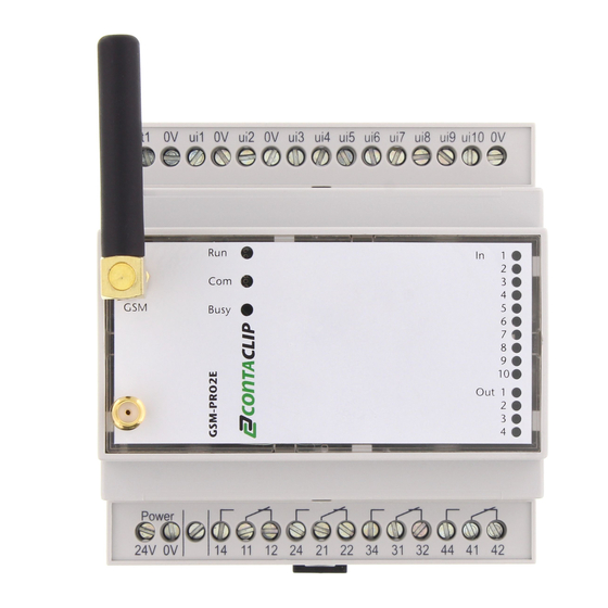
GSM-PRO2 Connect the antenna Connect the GSM antenna on the GSM connector on the module. Connect the GPS antenna on the GPS connector on the module. Connect to power Connect the 24V and 0V to a 24VDC power supply (10..30VDC). - 7 -... -
Page 10: Connect To Pc
GSM-PRO2 Connect to PC With the lid removed, connect a USB cable to the micro USB socket on the module, and the other end to a USB port on a PC. NOTE: Make sure to install the interface software and drivers before connecting the module to a PC. LED description 3.5.1 Module status indication... -
Page 11: Configuration
GSM-PRO2 4 Configuration Connect to the module Connect 24VDC to the module and connect a USB cable between the module and a PC USB port. Wait for the module to start up and run the module interface software. On start up the configuration software searches all available COM ports for an available module. When found, the software downloads the diagnostic data and prompts to download the settings from the device. -
Page 12: Configuration
GSM-PRO2 Configuration Press the ‘menu’ button to edit the module: 4.2.1 Upload to the module Upload current configuration software settings to the module. NOTE: uploading settings to the module overwrites all settings within the module. Therefore it is highly recommended to download the settings from the module first, before uploading any new changes. 4.2.2 Download from module Download all settings from the module into the interface. -
Page 13: Reset Module To Default
GSM-PRO2 4.2.5 Reset module to default Restore all settings in the module back to factory default. - 11 -... -
Page 14: Diagnostics
GSM-PRO2 Diagnostics After connecting to the module the diagnostics information is filled. This shows: • Registered GSM network or connection errors • Signal strength and RAT (Radio Access Technology) GPRS or 3G • Module firmware version • IMEI number • Error messages: SIM PIN code required SIM PUK code required... -
Page 15: Contacts
GSM-PRO2 Contacts The interface software has a contacts list to store all your contacts for further usage. All actions in the contacts list will auto save on completion. 4.4.1 Add/delete contacts To add a contact to the contacts click on the add button and fill in the name and phone number or email address. -
Page 16: Settings
GSM-PRO2 5 Settings Main settings The main functions of the module are configured in the ‘settings’ tab: • Module name • Module Phone Number • SIM pin number, this is the pin number to access the SIM card. • Admin user. The admin user has full access to the module and receives no general messages. Mobile Data Mark this checkbox if a data connection is required. -
Page 17: General Messages
GSM-PRO2 6 general messages 6.1.1 Periodical message The module can send a periodical message on a user defined time: • Daily, set the time • Weekly, set the day and time • Monthly, set the day of the month and time •... -
Page 18: Log
GSM-PRO2 7 Log The module can keep log files with a maximum size of 100kB. Select an email address in the Log tab to auto send a full log and continue logging. When no email is selected and a log is 90% full the module sends a warning message to the users in the general message tab. -
Page 19: Counter Log
GSM-PRO2 7.1.3 Counter log When activated the counter log logs the value from activation start until midnight. After this it logs the value between midnight and midnight. When connected, view this log by clicking ‘download counter log’. View remote by sending: clog directly followed by a valid email address (e.g. -
Page 20: Software Updates
GSM-PRO2 8 Software updates Update The module can perform firmware updates remote(OTA) or when connected by USB to a PC. Over The Air (OTA) covers remote actions where the data is transmitted over mobile data. 8.1.1 Manual firmware updates Download the latest firmware at: http://www.conta-clip.com/en/service/ Access the ‘advanced settings’... -
Page 21: O Configuration And Messaging
GSM-PRO2 9 I/O configuration and messaging The module responds to read and write commands. Commands are preceded by an ‘r’ for read and ‘w’ for write actions. All SMS commands are NOT case sensitive. Digital Output 9.1.1 Configuration The following items can be configured with the software: •... -
Page 22: Using The One-Shot Function
GSM-PRO2 9.1.4 Using the one-shot function The digital outputs can be set for a given time from 1 to 10 hours. When this command is received, the DO sets to 1 and after the number of seconds the DO falls back to 0. The one shot function is called by selecting the DO followed by a ‘t’... -
Page 23: Universal Inputs
GSM-PRO2 Universal Inputs The universal inputs can individual be configured as: • Analog input AI (0..10V or 0..20mA) • Digital input DI (default) The selected button represents the chosen function and is set after uploading. 9.2.1 Select receivers The recipients receive the messages of the selected UI. NOTE: Selected UI users do not have any rights to send commands to the module. -
Page 24: Wiring Example
GSM-PRO2 • The min. value represents the scaled value for 0V • The max. value represents the scaled value for 10V or 20mA • Lower limit threshold • Upper limit threshold • Minimal change (hysteresis) • Send only the user defined text, this sends only the text defined in the message box, no module name, IO name and timestamp. -
Page 25: Digital Inputs
GSM-PRO2 Digital Inputs The Digital Inputs can generate messages when: A rising flank is detected: the status changes from 0 to 1 A falling flank is detected: the status changes from 1 to 0 9.4.1 Configuration Configure the following items: •... -
Page 26: Counter
GSM-PRO2 Counter The module has in input which can count up to 1000 pulses per second. The module can send messages on a given threshold. It can also log the counter values for each day. Configure the following items: • Activate Counter •... -
Page 27: Read All Io Statuses
GSM-PRO2 Read all IO statuses To retrieve the status of all IOs send: rall. The module answers: With the module name and the status of all IO’s and extensions. To send the full IO status to an email address send: rall<email>. Link multiple modules It’s possible to link multiple modules by SMS. -
Page 28: Extensions
GSM-PRO2 10 Extensions The number of IO on the module can be extended with external modules. These are connected with a bus driven interface by simple pushing the modules into another with the connector on the left side of the module. 10.1 Configuration 10.1.1 Hardware To adjust the bus address on each extension lift the lid with a small flat screwdriver and turn the rotary switch... -
Page 29: Gsm-Pro-4Do
GSM-PRO2 Configure the extension(s) for the module by clicking IO->Extensions. Click the ‘Add’ button to add a module. Fill the bus address as adjusted on the extension and choose the type of module. Click ‘Add’ and the module appears in the list. Repeat this step for the number of extensions connected to the module. Each added module can be configured with a module name and up to 10 users who have access to the module in case of outputs, or receive messages in case of inputs. -
Page 30: Gsm-Pro-8Ai
GSM-PRO2 • Rising / Falling flank message • Send only the user defined text, this sends only the text defined in the message box, no module name, IO name and timestamp. • Rising / Falling flank message delay: the changed status must be held for the given time before being accepted In the following examples all Di’s are connected to be pulled-up: 10.4 GSM-PRO-8AI... -
Page 31: Wiring Example
GSM-PRO2 NOTE: Due to time consuming tasks the delay on extensions has an inaccuracy of up to 5 seconds. 10.4.2 Wiring example In the following example Ai1 and AI4 are connected to an analog source. 10.4.3 Current input When using the GSM-PRO-8AI as 0..20mA current input a 250Ω resistor has to be placed on the header marked with Ri on the number corresponding to the input. -
Page 32: Gsm-Pro-4Ao
GSM-PRO2 10.5 GSM-PRO-4AO The 4AO has 4 0..10V outputs. The following items can be configured with the software for each output: • Output name. • User defined instructions to change the value of the output. To change the output status by a default message SMS: WAOnxEa where n is the output number, x the value in Volts and a the bus address. -
Page 33: Modbus Slave
GSM-PRO2 11 Modbus Slave The GSM-PRO2 can be connected to a PLC as a communication device. NOTE: It’s only possible to use a GSM-PRO2 (not the PRO2E) to act as a Modbus Slave because the GSM-PRO2E uses the bus connection for different (internal) purposes. 11.1 Hardware The GSM-PRO2 uses a 2 wire RS485 connection with the RTU Modbus protocol. -
Page 34: Message Registers
GSM-PRO2 11.2.2 Message registers Each of the 10 message registers can be configured with a text message and recipients. The default value of each register is ‘0’. When written to ‘1’ the GSM-PRO2 will send the message to the recipients and writes the value of the register back to ‘0’. -
Page 35: Other Messages
GSM-PRO2 12 Other messages 12.1 Module reset Reset with the following command: wreset. This performs a full module reset. The module answers with the power cycle message if set. 12.2 Stop messaging The command: mesoff will stop the module from sending any more messages. The module answers: ‘messaging turned off’. -
Page 36: Additional Software
GSM-PRO2 13 Additional software 13.1 GSM-PRO2 App The GSM-PRO2 App can be downloaded from the Google Play store for Android, from the Apple Store for Apple iOS and the Windows App store for Windows Phone. With the app you can view the IO status and events or set an output by simple tapping your smart phones touch screen. -
Page 37: Troubleshooting
GSM-PRO2 14 Troubleshooting 14.1 Cannot connect to the PC, no module found • Re-connect the USB cable from the PC. • Reboot the PC (after driver installation). • Start the program as administrator, right click->Run as administrator. • Try a different USB port, remove any hubs or extension cables. 14.2 No connection to GSM network •... -
Page 38: Appendix: Sms Commands
GSM-PRO2 15 appendix: SMS commands RALL => read all IOs WDOnx => write digital output number n to status x WDOnTxxxx => write digital output number n to status 1 for xxxx seconds WRESET => device reset CCFm => mail configuration file to email address m EVLOGm =>... - Page 39 GSM-PRO2 WDOnTxxxxEa => write digital output number n to status 1 on extension address a for xxxx seconds Location => Send a link to Google Maps with the position of the module HELP => view all SMS commands => check signal quality and strength =>...
-
Page 40: Appendix: Diagnostic Commands
GSM-PRO2 16 APPENDIX: diagnostic commands MPWR => device power (V) => request ui number n, use ‘0’ for all ui’s => set do to status x Mbwaaarrrv => Modbus write address aaa(3 digit), register address rrr (3 digit), value Mbraaarrrv =>... -
Page 41: Appendix: Signal Strengths
GSM-PRO2 17 Appendix: signal strengths Appendix Signal strengths % (percentual) Remark 0,0% Too low for connectivity 3,2% Too low for connectivity 6,5% Too low for connectivity 9,7% Too low for connectivity 12,9% Too low for connectivity 16,1% Too low for connectivity 19,4% Too low for connectivity 22,6%... -
Page 42: Appendix: Modbus Registers
GSM-PRO2 18 Appendix: Modbus Registers Description Read/Write Register Data description Saved Min. Default Max. Restart Write to 0 to restart. Message 1 Write to 1 to send message Message 2 Write to 1 to send message Message 3 Write to 1 to send message Message 4 Write to 1 to send message Message 5...
Need help?
Do you have a question about the GSM-PRO2-GPS and is the answer not in the manual?
Questions and answers