Table of Contents
Advertisement
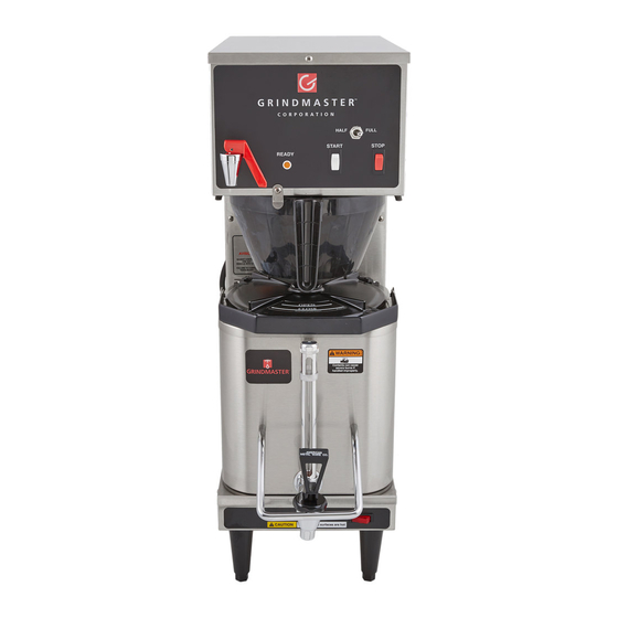
P200E Shuttle & RAPS200E
Airpot/Shuttle Brewer Series
Operation and Instruction Manual
Table of Contents
Installation and Start-up ......................................1-2
............................................................3
Adjustments ..........................................................4-5
..........................................................5-6
............................................................7
Troubleshooting
Filling Problems .................................... 8
Heating Problems ................................. 9
Brewing Problems ................................ 10
Exploded View for P200-E ....................................11
Exploded View for P200 (G version)......................12
Exploded View for RAPS200-E..............................13
Exploded View for RAPS200 (G version) ..............14
Rough-In Drawing for P200-E................................15
Rough-In Drawing for RAPS200-E ........................16
Wiring Diagram for P200E/RAPS200-E ..........17
Prior authorization must be obtained from
Grindmaster for all warranty claims.
Water Hook-up
1) Water inlet (supply) fitting is located at rear of unit.
2) Use 1/4" copper or flexible water line to prevent strain. Do not use low temperature plastic tubing. The connection
is 1/4" flare.
3) Water line pressure must be from 30 to 70 psi.
4) Hot (up to 160F) or cold water may be used. Hot water offers faster recovery between brews, (Use cold water only
if in-line water filters are implemented before the brewer).
5) Install a shut-off valve near the brewer.
6) Installing a filtering system can improve the taste of brewed coffee and extend the life of the brewer. If your water
has high calcium (lime), chlorine, or iron content, this is especially important. The filter should be the lime inhibiting
type if cold water is used. Contact our Customer Service Department to select the filter for your conditions.
Printed in the U.S.A.
Installation
WARNING: ELECTRIC SHOCK HAZARD!
!
INSTALLATION OF THIS APPLIANCE SHOULD BE PERFORMED BY
QUALIFIED SERVICE PERSONNEL ONLY. IMPROPER
INSTALLATION COULD RESULT IN ELECTROCUTION.
See rough-in drawings in this manual for dimensions and locations of
electric and water input.
Set-Up/Position
1) Remove the brewer from the packing material and attach its legs.
2) Position the brewer on a strong, stable table or counter. Check
the level front to back and side to side. Adjust the legs to the
correct level.
IMPORTANT:
THE PERSON INSTALLING THIS APPLIANCE IS RESPONSIBLE
FOR ENSURING THAT ELECTRIC AND WATER CONNECTIONS
MEET THE REQUIREMENTS OF THE NATIONAL ELECTRIC
CODE, NATIONAL PLUMBING CODE, AND ANY LOCAL
ORDINANCES.
Grindmaster Corporation™
4003 Collins Lane
Louisville, KY 40245 USA
(502) 425-4776
(800) 568-5715 (Technical Service Only)
FAX (502) 425-4664
www.grindmaster.com
(800) 695-4500
1004 FORM # AM-308-06
Part # A090-085
Advertisement
Table of Contents

Subscribe to Our Youtube Channel
Related Manuals for Grindmaster P200E


Summary of Contents for Grindmaster P200E
-
Page 1: Table Of Contents
Exploded View for RAPS200-E...13 Exploded View for RAPS200 (G version) ...14 Rough-In Drawing for P200-E...15 Rough-In Drawing for RAPS200-E ...16 Wiring Diagram for P200E/RAPS200-E ...17 Prior authorization must be obtained from Grindmaster for all warranty claims. Water Hook-up 1) Water inlet (supply) fitting is located at rear of unit. - Page 3 Installation (con't.) Electric hook-up The electric ratings for your brewer are printed on its nameplate. Typical electric ratings are: 120V, 1.65 kW, 15 Amp, 1 phase. The brewer should be connected to its own circuit with a fused disconnect switch or a circuit breaker near the brewer.
-
Page 4: Operation
Operation CAUTION: HOT LIQUID HAZARD WATER USED FOR BREWING COFFEE IS VERY HOT. USE CAUTION WHEN BREWING, POURING, OR TRANSPORTING COFFEE. ACCIDENTAL SPILLS MAY RESULT IN SEVERE BURNS. Place an empty, warm Shuttle under the brew head. Turn on the warmer once a Shuttle is in place, or place an empty 1.9L to 3.0L airpot under the brewing head. -
Page 5: Adjustments
Adjustments WARNING: ELECTRIC SHOCK HAZARD DANGEROUS ELECTRIC VOLTAGES ARE PRESENT NEAR ADJUSTABLE COMPONENTS. ALL ADJUSTMENTS SHOULD BE PERFORMED BY QUALIFIED SERVICE PERSONNEL ONLY. All adjustable components are located under the top cover. To access these parts: Unplug the brewer. Remove the screw fastening the top cover. Remove the top cover. Brew Volume Adjustment The brew volume of the P200/RAPS200 brewer is controlled by its timer. -
Page 6: Cleaning
Thermostat Adjustment The thermostat controls the water temperature in the tank. Factory setting is 195 degrees F. This is the ideal temperature for brewing coffee. Water should never boil in the tank. If water is boiling in the tank, adjust the temperature appropriately. Standard Mechanical Thermostat: Shut off power and unplug brewer. - Page 7 Weekly or Bi-Weekly, Depending on Use (P200 Only): Fill Shuttle with one gallon of hot water. Pour the recommended concentration of urn cleaner into the Shuttle liners (Excessive amounts of cleaner will attack the stainless steel). Urn cleaners that have been used successfully: DIP-IT, manufactured by Economics Laboratories, Inc.
-
Page 8: Service
Service The rest of this manual contains information to help the service person who is working on this equipment. This section has information on performing common service tasks. To Drain The Water Tank CAUTION: HOT LIQUIDS / BURN HAZARD WATER IN TANK IS VERY HOT. USE CAUTION WHEN DRAINING TANK. ACCIDENTAL SPILLS MAY RESULT IN SEVERE BURNS. -
Page 9: Filling Problems
Troubleshooting: Filling, Heating, and Brewing The filling system consists of the following components: • Liquid Level Control, located behind the brewer front panel. • Liquid Level Probes, located on the tank top, secured by wing nut, under the top cover •... -
Page 10: Heating Problems
Friday, 8 a.m. - 6 p.m. EST) or an authorized service center in your area. Please have the model and serial numbers ready so that accurate information can be given. Prior authorization must be obtained from Grindmaster Technical Services Department for all warranty claims. -
Page 11: Brewing Problems
Troubleshooting: Filling, Heating, and Brewing (con’t.) The brewing system consists of the following components: • Start and Stop switches, located on the front control panel. • Brew Timer, located in the top control section under the top cover. Problem Possible Cause Brew volume too Timer out of ad- large or too small. -
Page 12: Exploded View For P200-E
Exploded View for the P200-E ITEM DESCRIPTION PART # P200/RAPS200 Brewers Page 11... -
Page 13: Exploded View For P200 (G Version)
Exploded View for the P200 (G version only) ITEM DESCRIPTION PART # P200/RAPS200 Brewers Page 12... -
Page 14: Exploded View For Raps200-E
Exploded View for the RAPS200-E ITEM DESCRIPTION PART # P200/RAPS200 Brewers Page 13... -
Page 15: Exploded View For Raps200 (G Version)
Exploded View for the RAPS200 (G version only) ITEM DESCRIPTION PART # P200/RAPS200 Brewers Page 14... -
Page 16: Rough-In Drawing For P200-E
Rough-In Drawing for the P200-E P200/RAPS200 Brewers Page 15... -
Page 17: Rough-In Drawing For Raps200-E
Rough-In Drawing for the RAPS200-E P200/RAPS200 Brewers Page 16... -
Page 18: Wiring Diagram For P200E/Raps200-E
Wiring Diagram for P200-E/RAPS200-E P200/RAPS200 Brewers Page 17... -
Page 20: Grindmaster Corporation
We use the finest components and materials, and employ quality engineering standards and tests. The P200E Brewer is warranted for a period of one year from date of shipment. This warranty will include parts and labor but will not cover transportation and shipping charges and will be limited to equip- ment sold to commercial purchasers and installed in the continental U.S.A., Hawaii, Alaska and Canada.
Need help?
Do you have a question about the P200E and is the answer not in the manual?
Questions and answers