Table of Contents
Advertisement
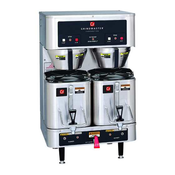
Shuttle Brewer & Airpot/Shuttle Brewers
Operation and Instruction Manual
Table of Contents
Installation and Start-up ....................................... 1-2
Operation .......................................................... 3
Adjustments ........................................................ 4-7
Care and Cleaning ............................................... 8-9
Service ............................................................... 9-10
Troubleshooting
Filling Problems .................................... 11
Heating Problems ................................. 12
Brewing Problems ................................ 13
Parts Illustrations
Models P300E & P400E ....................... 14
Model RAP400E ..................................... 15
Model RAPS400E ................................... 16
VSB-400................................................ 17
Shuttle CS-LL .......................................... 18
Rough-In Drawings
Model P-300.......................................................... 19
Model P-400 ......................................... 20
Model RAP-300 ......................................... 21
Model RAP-400 ........................................ 22
Model RAPS-300 ....................................... 23
Model RAPS-400 ..................................... 24
VSB-300 .................................................. 25
VSB-400 ................................................ 26
Wiring Diagrams
P300E/P400E with 1 Batch Timer ......... 27
P300E/P400E with 2 Batch Timer........ 28
RAP300E/RAP400E................................29
RAPS300E/RAPS400E........................30
Drawing #091-548 .................................31
Drawing #091-182 ....................................32
Warranty ................................................................... 36
Water Hook-up
1) The water line may enter through holes on the rear or the bottom of the brewer. Use the right hand opening for water.
2) Use 3/8" copper or flexible water line to prevent strain. Do not use low temperature plastic tubing. The connection
to the fill valve is 3/8" flare.
3) Water line pressure must be from 30 to 70 psi.
4) Hot (up to 160°F) or cold water may be used. Hot water offers faster recovery between brews.
5) Install a shut-off valve near the brewer.
6) Installing a filtering system can improve the taste of brewed coffee and extend the life of the brewer. If your water
has high calcium (lime), chlorine, or iron content, this is especially important. The filter should be the lime inhibiting
type if cold water is used. Contact our parts department to select the filter for your conditions.
Prior authorization must be obtained from Grindmaster Corporation for all warranty claims.
PRINTED IN U.S.A.
For Models P300E, P400E, RAP300E,
RAP400E, RAPS300E, RAPS400E
Installation:
ELECTRIC SHOCK HAZARD!
Installation of this appliance should be performed by
qualified service personnel only. Improper installation could
result in electrocution.
See rough-in drawings in this manual for dimensions and locations of
electric and water input.
Set-Up/Position
1) Remove the brewer from the packing material and attach its legs.
2) Position the brewer on a strong, stable table or counter. Check the
level front to back and side to side. Adjust the legs to the correct level.
IMPORTANT:
THE PERSON INSTALLING THIS APPLIANCE IS RESPONSIBLE
FOR ENSURING THAT ELECTRIC AND WATER CONNECTIONS
MEET THE REQUIREMENTS OF THE NATIONAL ELECTRIC
CODE, NATIONAL PLUMBING CODE, AND ANY LOCAL
ORDINANCES.
The electric and water hook-up locations are behind the front panel.
Remove the four screws fastening this panel for access to these
connections.
WARNING
Grindmaster Corporation
4003 Collins Lane
Louisville, KY 40245 USA
(502) 425-4776
(800) 695-4500 (USA & Canada only)
(800) 568-5715 (Technical Service Only)
FAX (502) 425-4664
www.grindmaster.com
0306 FORM # AM-309-06
Part # 090-077
Advertisement
Table of Contents

Related Manuals for Grindmaster P300E


Summary of Contents for Grindmaster P300E
-
Page 1: Table Of Contents
(lime), chlorine, or iron content, this is especially important. The filter should be the lime inhibiting type if cold water is used. Contact our parts department to select the filter for your conditions. Prior authorization must be obtained from Grindmaster Corporation for all warranty claims. © Grindmaster Corporation, 1998 PRINTED IN U.S.A. - Page 2 Installation (con't) Electric Hook-up The electric ratings for your brewer are printed on its nameplate. Typical electric ratings are: P300, P400, RAP300, RAP400 Optional 120/208V, 3.8kW, 18A or 120/240V 5.0kW, 21A, 1 phase Standard 120/208V, 5.0kW, 24A or 120/240V 6.6kW, 28A, 1 phase RAPS300, RAPS400 Standard 120/208V, 4.4KW 21A or 120/240V, 5.6KW 24A, 1 phase...
-
Page 3: Operation
Operation HOT LIQUID HAZARD! Water used for brewing coffee is very hot. Use caution when brewing, pouring, or transporting coffee. Accidental spills may result in severe burns. RAPS Brewers require the accessory warmer base placed over the pegs on the brew shelf before brewing into a shuttle. -
Page 4: Adjustments
Adjustments Electrical Shock Hazard! Dangerous electric voltages are present near adjustable components. All adjustments should be performed by qualified service personnel only. All adjustable components are located under the top cover. To access these parts: Shut off the electric line to the brewer or unplug the brewer. Remove the single screw fastening the top cover. -
Page 5: Bypass Valve
Two Batch Timer with Knob Adjustment, See Figure 2: This timer is adjustable from 15 seconds to 5 minutes. Locate the adjustment knobs under the top cover. Set this timer by adjusting the knob. The batch selector switch picks the adjustment potentiometer which the timer will see. -
Page 6: Bypass Setting
Shut off and open brewer as described at the beginning of the adjustments section. Locate the bypass valve for the brew head you wish to adjust. Valve is on the right and front of the BREW valve. Open the valve (counter clockwise) to the desired setting. Use the table below as a guide: BYPASS SETTING closed 1 turn... - Page 7 into the shaft. Turn the calibration screw counter clockwise to increase the maximum temperature. Optional Solid State Thermostat: This control maintains temperature within 3°F. The adjustable range is from 155°F to 205°F. See Figure 6. Shut off power and open top cover. Locate thermostat on bracket mounted to front panel.
-
Page 8: Care And Cleaning
Cleaning Burn Hazard! Hot liquids and surfaces are present in this equipment. To avoid burns use caution when cleaning. Rinse hot parts with cold water before cleaning. Use gloves or a heavy cloth when removing hot parts from brewer. After Each Brew: Dispose of grounds and rinse brew basket. -
Page 9: Service
Fill shuttles with one gallon, 2/3 full, of hot water. Pour into the shuttle liners the recommended concentration of urn cleaner (excessive amounts of cleaner will attack the stainless steel). Urn cleaners that have been used successfully: DIP-IT, manufactured by Economics Laboratories, Inc. 4 Corporate Park Drive White Plains, NY 10604 OXYLITE, manufactured by Avril, Inc., Syndet Division... -
Page 10: Service
Service (con't) Drain Water Tank Always empty the tank before shipping. Draining of tank should be performed by a qualified service technician. The tank contains very hot water. May cause severe burns. Note: Brewer may contain over 5 gallons of hot water. Prepare a heat resistant container to drain tank water into. -
Page 11: Filling Problems
Troubleshooting: Filling, Heating, and Brewing The filling system consists of the following components: • Liquid Level Control, located behind the brewer front panel. • Liquid Level Probes, located on the tank top, secured by wing nut, under the top cover. •... -
Page 12: Heating Problems
Canada only) Monday thru Friday 8 am - 8 pm EST or an authorized service center in your area. Please have the model and serial numbers ready so that accurate information can be given. Prior authorization must be obtained from Grindmaster Corporation’s Technical Service Department for all warranty claims. Shuttle Brewers & Airpot/Shuttle Brewers... -
Page 13: Brewing Problems
Troubleshooting: Filling, Heating, and Brewing The brewing system consists of the following components: • Start and Stop, switches located in the top control panel. • Brew Timer, located in the top control section under the top cover. • Brew Valve, located in the top control section under the top cover. Problem Possible Cause Brew volume too... -
Page 14: Models P300E & P400E
Parts Illustration for Models P300E & P400E Item Part # Description A545-034 LEG, 4” PLASTIC W/ SS FOOT A545-015 LEG, 4” SS (OPTIONAL) A537-043 HOT WATER FAUCET W/ NUT A531-035 TERMINAL BLOCK A531-026 TOGGLE SWITCH A549-006 LIQUID LEVEL CONTROL BRD... -
Page 15: Model Rap400E
Parts Illustration for Model RAP400E Item Part # Description A548-072 LEG, RUBBER (RAP400) A545-004 LEG, PLASTIC 4” (OPTIONAL RAP 400) A548-090 LEG, PLASTIC PLUG (RAP300) A531-035 TERMINAL BLOCK A549-006 LIQUID LEVEL BOARD AAP-3 AIRPOT APT400-105 SPRAY HEAD ABB1.5P BREW BASKET, PLASTIC A537-129 BREW VALVE A531-005... -
Page 16: Model Raps400E
Parts Illustration for Model RAPS400E Item Part # Description A545-034 LEG, 4” PLASTIC W/ SS FOOT A545-015 LEG, 4” SS (OPTIONAL) A537-043 HOT WATER FAUCET W/ NUT A531-035 TERMINAL BLOCK AABW-R ACCESSORY WARMER RIGHT AAP-3 AIRPOT 3 LITER A549-006 LIQUID LEVEL CONTROL BOARD APT400-105 SPRAY HEAD ACS-LL SHUTTLE W/ LOCKING LID... -
Page 17: Vsb-400
Parts Illustration for Model VSB-400 Item Part # A545-034 LEG, 4” PLASTIC W/ SS FOOT A545-015 LEG, 4” SS (OPTIONAL) A531-035 TERMINAL BLOCK A549-006 LIQUID LEVEL BOARD AVS-1.5 SHUTTLE VACUUM APT400-105 SPRAY HEAD ABB1.5P BREW BASKET, PLASTIC A537-129 BREW VALVE A531-005 STOP SWITCH (before March 2000) A531-063... -
Page 18: Shuttle Cs-Ll
Parts Illustration for Shuttle CS-LL A537-049 UPPER FAUCET ASSEMBLY Upper Faucet A537-049 Shuttle Brewers & Airpot/Shuttle Brewers Item A537-053 A522078 A718-018 A725-092 A713-027 A548-142 A548-140 A61365 * S.S. Cover used until August 2001 A537-055 HANDLE A522132 BONNET NUT A522120 SPRING A537-047 PLASTIC STEM A522102 SILICONE SEAT CUP... -
Page 19: Model P-300
Rough-In Drawing for Model P-300 Shuttle Brewers & Airpot/Shuttle Brewers Page 19... -
Page 20: Model P-400
Rough-In Drawing for Model P-400 Shuttle Brewers & Airpot/Shuttle Brewers Page 20... -
Page 21: Model Rap-300
Rough-In Drawing for Model RAP-300 Shuttle Brewers & Airpot/Shuttle Brewers Page 21... -
Page 22: Model Rap-400
Rough-In Drawing for Model RAP-400 Shuttle Brewers & Airpot/Shuttle Brewers Page 22... -
Page 23: Model Raps-300
Rough-In Drawing for Model RAPS-300 Shuttle Brewers & Airpot/Shuttle Brewers Page 23... -
Page 24: Model Raps-400
Rough-In Drawing for Model RAPS-400 Shuttle Brewers & Airpot/Shuttle Brewers Page 24... -
Page 25: Vsb-300
Rough-In Drawing for Model VSB-300 WATER Shuttle Brewers & Airpot/Shuttle Brewers Page 25... -
Page 26: Vsb-400
Rough-In Drawing for Model VSB-400 Shuttle Brewers & Airpot/Shuttle Brewers Page 26... -
Page 27: P300E/P400E With 1 Batch Timer
Wiring Diagram for P300E/P400E, with 1 Batch Timer NOTE: THIS DRAWING SHOWS COMPONENTS ON STANDARD MODEL ONLY. SEE 091-548 FOR WIRING OF BREWER OPTIONS Shuttle Brewers & Airpot/Shuttle Brewers Page 27... -
Page 28: P300E/P400E With 2 Batch Timer
Wiring Diagram for P300E/P400E, with 2 Batch Timer Shuttle Brewers & Airpot/Shuttle Brewers NOTE: THIS DRAWING SHOWS COMPONENTS ON STANDARD MODEL ONLY. SEE 091-548 FOR WIRING OF BREWER OPTIONS Page 28... -
Page 29: Rap300E/Rap400E
Wiring Diagram for RAP300E/400E NOTE: THIS DRAWING SHOWS COMPONENTS ON STANDARD MODEL ONLY. SEE 091-548 FOR WIRING OF BREWER OPTIONS Drawing #091-545 Shuttle Brewers & Airpot/Shuttle Brewers Page 29... -
Page 30: Raps300E/Raps400E
Wiring Diagram for RAPS 300/400E NOTE: 1) TWO SETS OF RECEPTACLE COMPONENTS ONLY PROVIDED ON TWIN RAPS400E MODEL. DELETE GROUP IN DASHED BOX FOR RAPS300E. 2) THIS DIAGRAM SHOWS COMPONENTS ON STAN- DARD MODEL ONLY. SEE 091-548 FOR WIRING OF BREWER OPTIONS. - Page 31 Wiring Diagram #091-548 NOTES: 1) IF PROVIDED WITH OPTION C21A, THREE HEATERS, SEE HEATER WIRING DIAGRAM 091-182. 2) WHEN PROVIDED WITH OPTION C14, AUTOMATIC WARMER SHUTOFF, SUBSTITUTE ACTIVATED SWITCH FOR WARMER TOGGLE. Shuttle Brewers & Airpot/Shuttle Brewers NOTE: ONE GROUP OF WARMER COMPONENTS PER BREW HEAD ON P AND RAPS MODELS.
-
Page 32: Drawing #091-182
Wiring Diagram #091-182 * FOR 3 PHASE WIRING 1. MOVE WIRE 6 FROM L1 TO L3 2. CONNECT HEATER ACCORDING TO FIG. F ON CHART 3. FIG. F FOR 3 PH ONLY WIRES 5 6 7 8 ARE 8 AWG, 105°C 1 2 3 4 ARE 10 AWG, 105°C Shuttle Brewers &... - Page 33 Notes Shuttle Brewers & Airpot/Shuttle Brewers Page 33...
- Page 34 Notes Shuttle Brewers & Airpot/Shuttle Brewers Page 34...
- Page 35 Notes Shuttle Brewers & Airpot/Shuttle Brewers Page 35...
-
Page 36: Grindmaster Corporation
Call Grindmaster Corporation’s Service Department toll free at 1-800-695-4500, (Monday-Friday 8:00 am- 8:00 pm EST) or write to: Grindmaster Corporation’s Factory Service Center, P.O. Box 35020, Louisville, KY 40232. In order to receive warranty service, you must provide the serial number of the machine requiring service along with a description of the problem.
Need help?
Do you have a question about the P300E and is the answer not in the manual?
Questions and answers
We have an P4000E that is brewing strong coffee, and partial air **** level. We don't hear additional water entering machine. We also don't get a second batch.
A possible cause for the Grindmaster P300E brewing strong coffee with partial air level and not producing a second batch could be:
1. Cold Shuttle: If the shuttle is not warm, it can lower the brewed coffee temperature and affect extraction, leading to strong coffee. Ensure the warmer is on and the shuttle is heated before brewing.
2. Incorrect Coffee-to-Water Ratio: Using too much coffee or too little water can result in strong coffee. Check that the correct amount of ground coffee is used (6.5–8 ounces per gallon of water).
3. Brew Valve Issue: A limed-up or faulty brew valve may restrict water flow, causing incomplete brewing. A visual check and possible cleaning or replacement of the valve may be needed.
4. Thermostat Set Too High: If the brew thermostat is set too high, the system may not function correctly for a second batch. Adjust the thermostat as needed.
5. Timer Fault: If the timer is not providing the correct voltage output for a second brew cycle, it may need to be checked and replaced.
Checking and addressing these potential issues should help resolve the problem.
This answer is automatically generated