
Related Manuals for DAKOTA ULTRASONICS Z-300-0001


Summary of Contents for DAKOTA ULTRASONICS Z-300-0001
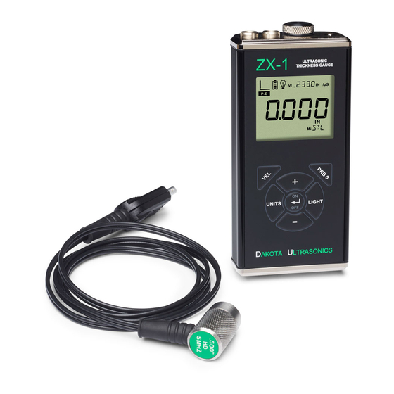
- Page 1 OPERATION MANUAL DAKOTA ULTRASONICS Ultrasonic Thickness Gauge P/N P-300-0002 Rev 1.10, March 2019...
-
Page 3: Table Of Contents
CONTENTS CHAPTER ONE INTRODUCTION ..............1 1.1 D ......................... 1 ISCLAIMER CHAPTER TWO KEYPAD, MENU, DISPLAY & CONNECTORS ..... 2 2.1 ON/OFF/ENTER K …..................... 2 2.2 PRB 0 K … ........................2 2.3 VEL K ….......................... 3 2.4 LIGHT K …. -
Page 5: Chapter One Introduction
CHAPTER ONE INTRODUCTION The Dakota Ultrasonics model ZX-1 is a basic dual element thickness gauge with the ability to locate blind surface pitting and internal defects/flaws in materials. Based on the same operating principles as SONAR, the ZX-1 is capable of measuring the thickness of various materials with accuracy as high as ... -
Page 6: Chapter Two Keypad, Menu, Display & Connectors
CHAPTER TWO KEYPAD, MENU, DISPLAY & CONNECTORS The Keypad 2.1 ON/OFF/ENTER Key The ON/OFF/ENTER key powers the unit ON or OFF. Since the same key is also used as an ENTER key, the gauge is powered off by pressing and holding down the key until the unit powers off. -
Page 7: Vel Key
ZX-1 Ultrasonic Thickness Gauge 2.3 VEL Key The VEL key is used to enter and exit the ZX-1's calibration mode. This mode is used to adjust the sound velocity value that the ZX-1 will use for a given material type. Enter a known velocity value for specific material type, or manually continue adjusting the value until the ZX-1 displays the correct thickness value using a test sample or calibration block with a known thickness. -
Page 8: The Display
Dakota Ultrasonics 2.7 The Display The ZX-1 uses a custom glass LCD backlit low temperature display for use in a variety of climate conditions. It contains graphic icons, as well as both 7 and 14 segment display areas. Let’s take a closer look and what all these things are telling Note: This display is used for multiple gauge models in the ZX &... -
Page 9: The Transducer
ZX-1 Ultrasonic Thickness Gauge G. Small 7 Segment: The material velocity, speed the sound wave travels through a given medium/material, is displayed in this area, informing the user what material the ZX-1 is currently calibrated too. This area is also used for alpha messages in the menu and edit modes. - Page 10 Dakota Ultrasonics This is a bottom view of a typical transducer. The two semicircles of the wear face are visible, as is the barrier separating them. One of the semicircles is responsible for conducting ultrasonic sound into the material being measured, and the other semicircle is responsible for conducting the echoed sound back into the transducer.
-
Page 11: Top End Cap
ZX-1 Ultrasonic Thickness Gauge When the transducer is removed from the surface, the display will hold the last measurement made. 2.9 Top End Cap The top end cap is where all connections are made to the ZX-1. The diagram above shows the layout and description of the connectors: Transducer Connectors Refer to Diagram: The transducer connectors and battery cover/probe zero disk are... -
Page 12: Chapter Three Principals Of Ultrasonic Measurement
CHAPTER THREE PRINCIPALS OF ULTRASONIC MEASUREMENT 3.1 Time versus thickness relationship Ultrasonic thickness measurements depend on measuring the length of time it takes for sound to travel through the material being tested. The ratio of the thickness versus the time is known as the sound velocity. In order to make accurate measurements, a sound velocity must be determined and entered into the instrument. -
Page 13: Temperature
ZX-1 Ultrasonic Thickness Gauge 3.5 Temperature Temperature has an effect on sound velocity. The higher the temperature, the slower sound travels in a material. High temperatures can also damage transducers and present a problem for various liquid couplants. Since the sound velocity varies with temperature it is important to calibrate at the same temperature as the material being measured. - Page 14 Dakota Ultrasonics surface of the test material does not have to be as flat in order to obtain good measurements. Dual element delay line transducers are have a usable range of 0.025” and up, depending on the material, frequency, and diameter.
-
Page 15: Chapter Four Selecting The Measurement Mode
CHAPTER FOUR SELECTING THE MEASUREMENT MODE 4.1 Which mode & transducer do I use for my application? High penetration plastics and castings The most common mode for these types of applications is pulse-echo. Cast iron applications require 1 - 5MHz frequencies, and cast aluminum requires a 7 - 10MHz frequency depending on the thickness. - Page 16 Dakota Ultrasonics Noisy Material Materials such as titanium, stainless steel, and aluminum may have inherent surface noise issues or mirroring effect. Higher frequency transducers 7 – 10MHz offer improved resolution to avoid erroneous measurements. Restricted access Measuring materials with extreme curvatures or restricted access are best suited for...
-
Page 17: Chapter Five Making Measurements
CHAPTER FIVE MAKING MEASUREMENTS The steps involved in making measurements are detailed in this section. The following sections outline how to setup and prepare your ZX-1 for field use. A manual zero must always be performed. A manual probe zero is performed using the reference disk (battery disk) attached to the top of the instrument. -
Page 18: Velocity Calibration
Dakota Ultrasonics 2) Be sure all six repeatability/stability bars in the top left corner of the display are fully illuminated and stable, and last digit of the measurement is toggling only +/- .001” (.01mm). 3) Press the key to perform the manual zero. “PRB0” will briefly be displayed on the screen, indicating the zero calculation is being performed. - Page 19 ZX-1 Ultrasonic Thickness Gauge Note: Pressing the key prior to pressing the key will abort the cal routine without saving any changes. 3) Press the key to set the velocity value and return to the measurement screen. The new velocity value will be shown at the top of the display. CHECK YOUR CALIBRATION! Place the transducer back on the calibration point and verify the thickness.
-
Page 20: Chapter Six Additional Features
CHAPTER SIX ADDITIONAL FEATURES 6.1 Units The ZX-1 will operate in both English (inches) or Metric (millimeters) units. The procedure to select the units is outlined as below: Units 1) Press the key to toggle inches/millimeters (IN/MM). 6.2 Light The ZX-1 uses a custom glass segmented display that is equipped with a backlight for use in low light conditions. -
Page 21: Lock
ZX-1 Ultrasonic Thickness Gauge Note: Pressing the key prior to pressing the key will abort to the measurement screen without saving changes. 3) When the desired LITE setting is displayed, press the key to set the status and edit the BRT (brightness) option. 4) Use the keys to scroll through the BRT (LO, MED, HI) options. -
Page 22: Factory Defaults
Dakota Ultrasonics 2) To unlock the ZX-1 repeat step one, but hold down the key while powering the ZX-1 on 6.4 Factory Defaults The ZX-1 can be reset to factory defaults at any time to restore the original gauge settings. This should only be used if the gauge is not functioning properly, or perhaps multiple features have been enabled and a clean start is needed. - Page 23 ZX-1 Ultrasonic Thickness Gauge 7) Repeat the steps above to set “MEDI” & “ZERO” back to their original settings noted in step three above.
-
Page 24: Appendix A - Velocity Table
APPENDIX A - VELOCITY TABLE Material sound velocity sound velocity in/us Aluminum 0.2510 6375 Beryllium 0.5080 12903 Brass 0.1730 4394 Bronze 0.1390 3531 Cadmium 0.1090 2769 Columbium 0.1940 4928 Copper 0.1830 4648 Glass (plate) 0.2270 5766 Glycerine 0.0760 1930 Gold 0.1280 3251 Inconel... - Page 25 ZX-1 Ultrasonic Thickness Gauge 0.1310 3327 Titanium 0.2400 6096 Tungsten 0.2040 5182 Uranium 0.1330 3378 Water 0.0580 1473 Zinc 0.1660 4216 Zirconium 0.1830 4648...
-
Page 26: Appendix B- Application Notes
APPENDIX B- APPLICATION NOTES Measuring pipe and tubing When measuring a piece of pipe to determine the thickness of the pipe wall, orientation of the transducers is important. The transducer should be oriented so that the gap (sound barrier) in the wear face is perpendicular (at a right angle) to the length (long axis) of the tubing, allowing both sides of the transducer to make the same amount of contact. - Page 27 ZX-1 Ultrasonic Thickness Gauge the probe be left in contact with the surface for as short a time as needed (intermittent contact) to acquire a stable measurement. Measuring laminated materials Laminated materials are unique in that their density (and therefore sound-velocity) may vary considerably from one piece to another.
- Page 28 Additionally, Dakota Ultrasonics warrants transducers and accessories against such defects for a period of 90 days from receipt by the end user. If Dakota Ultrasonics receives notice of such defects during the warranty period, Dakota Ultrasonics will either, at its option, repair or replace products that prove to be defective.
Need help?
Do you have a question about the Z-300-0001 and is the answer not in the manual?
Questions and answers