Table of Contents
Advertisement
Quick Links
Advertisement
Table of Contents

Related Manuals for Datavideo NVS-40D


Summary of Contents for Datavideo NVS-40D
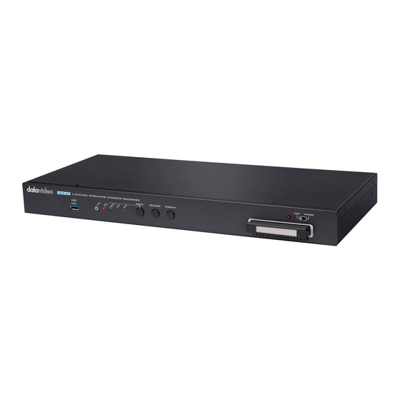
- Page 1 4 channel streaming encoder/recoder NVS-40...
-
Page 2: Table Of Contents
Table of Contents TABLE OF CONTENTS ....................2 FCC COMPLIANCE STATEMENT ................4 WARNINGS AND PRECAUTIONS ................4 WARRANTY ......................5 ..................... 5 TANDARD ARRANTY ................... 6 HREE ARRANTY DISPOSAL ........................ 6 CHAPTER 1 PRODUCT OVERVIEW ..............7 1.1 B .................... - Page 3 SERVICE AND SUPPORT ..................100 Disclaimer of Product & Services The information offered in this instruction manual is intended as a guide only. At all times, Datavideo Technologies will try to give correct, complete and suitable information. However, Datavideo Technologies cannot exclude that some information in this manual, from time to time, may not be correct or may be incomplete.
-
Page 4: Fcc Compliance Statement
AC adapter. If you are not sure of the type of power available, consult your Datavideo dealer or your local power company. 8. Do not allow anything to rest on the power cord. Do not locate this unit where the power cord will be walked on, rolled over, or otherwise stressed. -
Page 5: Warranty
Warranty Standard Warranty Datavideo equipment are guaranteed against any manufacturing defects for one year from the date of purchase. The original purchase invoice or other documentary evidence should be supplied at the time of any request for repair under warranty. -
Page 6: Three Year Warranty
Camera module, PCIe Card are covered for 1 year. The three-year warranty must be registered on Datavideo's official website or with your local Datavideo office or one of its authorized distributors within 30 days of purchase. Disposal For EU Customers only - WEEE Marking... -
Page 7: Chapter 1 Product Overview
The Datavideo NVS-40 supports SDI x 1 and HDMI x 4 video inputs (Channel 1 source can be either SDI or HDMI). The NVS-40 allows up to 4 1080P signal sources to be encoded to 8 streamings in different bitrates simultaneously. - Page 8 Multi-language Web UI including English, Simplified Chinese, Japanese and Traditional Chinese (Will be Available Soon) Dual Color LED Indicator Showing the status or detections. (About LED indicator related sections, please refer to Appendix1 and Appendix2). Supported input formats ...
-
Page 9: Chapter 2 Connections And Controls
Chapter 2 Connections and Controls 2.1 Front Panel Stream and Recording Stream Button Press this button to activate the RTMP/RTMPS/RTSP stream and press again to stop streaming. Note: Pressing the Stream button starts the stream for that device only and this stream button is used when you want to stream directly through the NVS-40 device rather than by the NVS-40 Web UI. - Page 10 Record Button Press the Record button to start recording your input source to the 2.5” SSD or HDD inserted into the front panel of the NVS-40. Press the Record button again to stop the recording. Note: Pressing the Record button starts recording for that device only and this record button is used when you want to record directly through...
- Page 11 SDI LED The SDI LED indicates the status of the first input channel. The first input channel of the NVS-40 allows either SDI or HDMI source. If the input for the first channel is SDI source, this SDI LED will be lit.
- Page 12 USB Port The USB port on the front panel of the NVS-40 is used for firmware update. Note: The USB port on the front panel of the NVS-40 is used for firmware update. The backup recording of the NVS-40 will be saved in the HDD or SSD inserted into the right side of the front panel.
- Page 13 indicator shows Lock/Unlock status of the SSD/HDD enclosure. When the SATA interface is connected correctly Lock/Unlock switch is pushed to the lock side, the SSD/HDD LED indicator will be lit. Green LED is On: The installation is finished/The SSD/HDD is ready Green LED is Blinking: In the recording LED is Off: SSD/HDD is removed/Error...
-
Page 14: Rear Panel
2.2 Rear Panel Audio Input RCA Unbalanced Audio Input Allows you to input an unbalanced stereo analog audio source for streaming and recording. XLR Balanced Audio Inputs Allows you to input up to two XLR balanced analog audio sources (CH1 & CH2) for streaming and recording. Video Input SDI/HDMI Input (for Channel 1 Video Input Only) Connect an SDI or HDMI video source to this SDI/HDMI... - Page 15 Connect an SDI cable from this connector to a monitor or projector with the SDI interface to output the SDI input source Others The LAN port is an auto-negotiation 10/100/1000 Base- T Ethernet port which connects the NVS-40 to an Ethernet network through a standard RJ-45 Ethernet cable.
-
Page 16: Chapter 3 System Diagram
Chapter 3 System Diagram... -
Page 17: Chapter 4 Quick Start Guide-Connection And Setting
Step 6. Please connect an RJ-45 Ethernet cable from the LAN port for the router to your PC/Laptop. Step 7. Please set your PC/laptop in DHCP mode. Step 8. Please download Datavideo IP Finder utility software “NVS-2X_IPFinder” on the Datavideo official website www.datavideo.com or by scanning the QR code. - Page 18 Step. 11. After the connected NVS-40 IP address is shown, please enter the IP address into the address bar of the web browser.
- Page 19 Step. 12. After connecting to the NVS-40 Web UI, there is a login interface that will be shown as following diagram for users to enter the default “Account” and “Password” when logging in NVS-40 Web UI for the first time. After the default Account and Password are entered, please press the “Sign in”...
-
Page 20: How To Install 2.5" Ssd/Removable Hdd
Note: The 2.5” SSD/HDD must be installed in the enclosure and inserted into the HDD tray on the front panel of the NVS-40 to start recording. 4.2 How to Install 2.5” SSD/Removable HDD How to Assemble 2.5” SSD/HDD in Removable Enclosure. 1. -
Page 21: Chapter 5 Nvs-40 Web Control User Interface
3. After the SSD/HDD is placed back into the enclosure and the four screws are screwed, the SSD/HDD enclosure will be shown as the diagram. 4. Finally, please insert the SSD/HDD enclosure into the HDD tray on the left side of the NVS- 40 and then slide the LOCK/UNLOCK switch to the LOCK side as shown... -
Page 22: Source
5.2 Source The tag1, 2, 3 and 4 represent the video and audio input sources for channel 1 to channel 4. Due to that the video input source for the channel 1 can be SDI, HDMI or IP Stream, users can see the SDI and HDMI tags for the channel 1 which are shown as following diagram. - Page 23 If the Input Source is HDMI If the Input Source is IP Stream The IP Stream function allows users to use the IP Stream to be the input source and the NVS-40 can acquire the streaming video remotely.
- Page 24 Please follow following steps for using the IP Stream to be the input source of the NVS-40. Step 1. Please copy the streaming address from the streaming source. Step 2. Please click “IP Stream” from the web UI of the NVS-40 and then please paste the copied streaming address to the “Source URL”...
- Page 25 The input source related information will be shown on the bottom of the “Source” page. If the streaming video is decoded by the NVS-40 correctly, the word “IP Stream” and resolution will be shown. Step 3. At this time, the NVS-40 can acquire the streaming video remotely. The interfaces for video and audio input sources for Channel 2 to Channel 4 are shown as following diagram.
- Page 26 For the input source, if “Line-in” or “XLR” is selected, there is a slider for users to adjust the volume. However, this interface also allow users to select the audio source to be “SMPTE”, “EBU” or “Manual”. After the setting is finished, please press the “Apply”...
-
Page 27: Encoder
5.3 Encoder Users can see the Encoder control page by pressing the Encoder option on the menu bar. There are five tags including tag1, tag 2, tag 3, tag4 and PGM which are shown in the “Encoder” control page. Each tag allows users to set parameters in two Encoders including Main Encoder and Sub Encoder. - Page 28 Main Encoder: Main Encoder: 30FPS 30FPS Sub Encoder: Sub Encoder: 15FPS 15FPS Total FPS=60+30+30+15+60+30+30+15=270<300 For the introduction about each drop-down menu in the Encoder page, please see following table. Resolution The Resolution drop-down menu allows users to select different Encoding resolutions.
- Page 29 Frame Rate The Frame Rate drop-down menu allows users to select different Frame Rates. Note: Please pay attention that the total frame rate setting for the Record+Stream must be within 300 FPS. Profile Users can select three Profile settings including High, Main and Baseline. Level Users can select different Encoding levels from the drop-down menu...
-
Page 30: Setting Steps And Important Notices For Encoder Option Setting (Take Youtube As An Example)
Video Bitrate (bps) Users can select different Video Bitrate settings from this drop-down menu. Audio Bitrate (bps) Users can select different Audio Bitrate Settings from this drop-down menu. Entropy Users can select different Entropy algorithm settings including CAVLC and CABAC from the drop-down menu. - Page 31 Note: For the live-streaming, the quality of the video is the most important. So, please make sure to set suitable resolution according to your network connection speed to assure that the streaming video can be played smoothly. It is recommended to test the data upload bitrates before starting the live-streaming.
-
Page 32: Important Notices For Setting The Encoder (Take Facebook Platform As An Example)
Step 6. Set the GOP. The recommended GOP values for the Youtube platform are shown as following table. Frequency for playing the I Frame (Key Frame): The recommended setting is 2 seconds and this value must not exceed 4 seconds. The setting values for the 2 seconds I Frame Interval are shown as following table. - Page 33 If the source resolution is 1920 x 1080, please set the video bitrate (bps) as 1280*720 from the drop-down menu due to that the upper limit for the resolution is 1280*720. Because the upper limit for the recommended video bitrate for the Facebook platform is 4000kbps, so, it is a must for users to set the video bitrate to less than 4mbps.
-
Page 34: Record
5.4 Record After pressing the Record option from the menu bar of the NVS-40 Web UI, users can see the Record option control page. There are five tags including tag 1, tag 2, tag 3, tag 4 and PGM. Each tag includes two Record settings including Main Record and Sub Record. -
Page 35: Streaming
For the introduction for each drop-down menu of the Record page, please see following table. Encoder Source Users can select Main Encoder, Sub Encoder or Disable from the Encoder Source drop-down menu. File Name Users can enter their desired File Name into the blank. File Type Users can save the recorded file in different file formats... -
Page 36: User Interface For Different Streaming Formats
can press the “Apply” button to apply the setting. Moreover, users can press the “Start Stream” or “Stop Stream” button to start or stop the streaming. 5.5.1 User Interface for Different Streaming Formats The streaming option of the NVS-40 Web UI provides different streaming formats for users including RTMP, RTMPS, RTSP, TS and HLS. - Page 37 For the introduction for each drop-down menu of the Streaming page, please see following table. Encoder Source Users can select Main Encoder, Sub Encoder and Disable from the Encoder Source drop- down menu.
- Page 38 Stream Type Users can select stream protocols including RTSP, RTMP, TS and HLS from this drop-down menu. Note: If users want to use the RTMPS streaming protocol, please select the RTMP Stream Type. RTMP URL Before starting the RTMP streaming, users need to obtain streaming server address and streaming...
- Page 39 RTMPS address into this RTMP URL column. Account and Password These two blanks allow users to enter the Account and Password of the RTSP streaming. The default account and password are shown as following. Account: root Password: root RTSP Port and RTSP HTTP Port These two blanks will show RTSP port No.
-
Page 40: Streaming-Rtsp (Use Rtsp Protocol)
PC/Laptop and then connect another end to the LAN port of a router. 4. Please open Datavideo IP Finder software and then please press the Scan button to find the IP address of the NVS-40. (Please refer to Chapter 4. Quick Start Guide- Connection and Setting) 5. - Page 41 9. Please press the “Start Stream” button and then the RTSP streaming address will be generated. 10. Please download the VLC media player from https://www.videolan.org and then install the software. 11. Please open the VLC and then click “Media” drop-down menu and then click “Open Network Stream”.
-
Page 42: Streaming-Ts (Use Ts Protocol)
PC/Laptop and then connect another end to the LAN port of a router. 4. Please open Datavideo IP Finder software and then please press the Scan button to find the IP address of the NVS-40. (Please refer to Chapter 4. Quick Start Guide-... - Page 43 5. Please enter NVS-40’s IP address into the address bar of the web browser to open the web control interface of the NVS-40. 6. Please click the Streaming option from the web control interface to open the streaming control interface. 7.
- Page 44 11. Please download VLC media player from https://www.videolan.org and then please install the software. 12. Please open the VLC and then click “Media” drop-down menu and then click “Open Network Stream”.
-
Page 45: Streaming-Rtmp (Use Rtmp Protocol) (Take Youtube As An Example)
13. Please enter the streaming address that is generated by the NVS-40 into the “Please enter a network URL” column and then please press the Play button for playing the streaming. Take above address as an example, the address will be udp://192.168.100.100:1000 5.5.4 Streaming-RTMP (Use RTMP Protocol) (Take Youtube as an Example) 1. - Page 46 5. The Server URL and Stream Name/Key will be shown on the bottom of the Youtube page. 6. Please open Datavideo IP Finder software and then please press the Scan button to find the IP address of the NVS-40. (Please refer to Chapter 4. Quick Start Guide- Connection and Setting) 7.
-
Page 47: Streaming-Rtmp (Use Rtmp Protocol) (Take Facebook As An Example)
10. Please copy the Server URL and Stream Name/Key that are provided by the Youtube Live website and then paste them into the RTMP URL column in the Streaming control page. The format for entering the Server URL and Stream Name/Key is shown as following. - Page 48 4. Please go to Facebook website https://www.facebook.com/live/create , and then please click “Create Live Stream” button. Note: In Facebook platform, each streaming must be within 4 hours. 5. The following screen will be shown, please check “Use a persistent stream key” and then please copy “Server URL”...
- Page 49 6. After the Server URL and the Persistent Stream Key are pasted into the column, please press the “Start Stream” button. rtmp://live-api-s.facebook.com:80/rtmp/10205210705024920?s_ps=1&s_sw=0&s_vt=api -s&a=AbyaFOlMSeHJpgTl 7. The preview screen will be shown on the Facebook live-stream page. Please choose the section that you want to post your live broadcast and the audience who can see the live broadcast.
-
Page 50: Streaming -Hls (Use Hls Protocol)
5.5.6 Streaming –HLS (Use HLS Protocol) 1. Please select your desired Encoder Source from the Streaming page and then choose HLS from the Stream Type drop-down menu. After that, please press the “Start Stream” button. 2. NVS-40 will generate a stream address with .m3u8 file extension. 3. - Page 51 1. Please download VLC media player from https://www.videolan.org and then please install the software. 2. Please open the VLC and then click “Media” drop-down menu and then click “Open Network Stream”.
- Page 52 3. Please enter the streaming address that is generated by the NVS-40 into the “Please enter a network URL” column and then please press the Play button for playing the streaming.
- Page 53 5.6 CG After pressing the CG option on the web control interface, users can see the CG option control page. There are five tags including tag 1, tag 2, tag 3, tag 4 and PGM for users to set different CG parameters for Channel 1, Channel 2, Channel 3, Channel 4 and PGM.
- Page 54 Text If users select text to be the CG source, users can enter their desired texts into this column. Location-X/Location-Y Users can determine the X-axis and Y-axis of the CG source. (Text/Picture) Width and Height Users can enter different values to determine the Width and Height of the CG source.
-
Page 55: How The Location X & Location Y Values Affect Cg Source
Text Size Please enter different figure to change the text size. File Path If users select a picture to be the CG source, please press the Browse button to select your desired picture from the hard disk of your PC or laptop. 5.6.1 How the Location X &... - Page 56 You are my Friend Example:Location-X=900,Location-Y=500...
- Page 57 2. Picture: Users can adjust the Location-X and Location-Y value to change the position of the inserted picture on the screen. Location-X: For the Location-X, the more the value, the more the picture will be moved from the left side to the right side. Location-Y: For the Location-Y, the more the value, the more the picture will be moved from the up side to the down side.
-
Page 59: Pgm
5.7 PGM After pressing the PGM option on the menu bar of the web UI, users can see the control page 0f the PGM option. The PGM option provides five modes for displaying the PGM screen including Quad View, Full Screen, POP, PBP and PIP. The main interface of the PGM option is shown as following diagram. - Page 60 1. Quad View: Please press the “Quad View” icon and then please press the “Apply” button for applying the setting. 2. Full Screen: Please press the “Full Screen” icon and then please select the channel that is desired to be shown in Full Screen mode. After that, please press the “Apply” button for applying the setting.
- Page 61 3. POP (Picture Outside Picture): Please press the POP icon and then please select the channels that are desired to be shown in POP mode. After that, please press the “Apply” button for applying the setting. 4. PBP (Picture By Picture): Please press the PBP icon and then please select the two channels that are desired to be shown in the PBP mode.
- Page 62 5. PIP (Picture in Picture): Please press the PIP icon and then please select the two channels that are desired to be shown in the PIP mode. After that, please press the “Apply” button for applying the setting.
- Page 63 5.7.1 Scale There is a “Scale” drop down menu including “Stretch”, “Fit” and “Full” in the PGM user interface for users to apply in the POP and PBP mode. Please see following paragraphs for the introduction of the three modes including “Stretch”, “Fit”...
- Page 64 1. The PGM option is set to POP mode and the Scale drop-down menu is set to “Stretch”. 2. The PGM option is set to POP mode and the Scale drop-down menu is set to “Fit”.
- Page 65 3. The PGM option is set to POP and the Scale drop down menu is set to “Full”. 4. The PGM option is set to PBP mode and the Scale drop-down menu is set to “Stretch”.
- Page 66 5. The PGM option is set to PBP and the Scale drop-down menu is set to “Fit”. 6. The PGM option is set to PBP and the Scale drop-down menu is set to “Full”.
- Page 67 5.7.2 PGM Background Color The Background Color option in the PGM option allows users to select different colors when displaying in PBP mode. Please follow following steps for changing the background color of the PGM option. Step 1. Please press the background color option and then please select your desired color by entering the RGB or HSB code to the right side of the pop-up color picker.
-
Page 68: Monitor
5.8 Monitor After pressing the Monitor option on the menu bar of the web UI, users can see the control page is shown. There are four HDMI frame rate including 60FPS, 50FPS, 30FPS and 25FPS for users to select. Moreover, it allow users to adjust the output volume. -
Page 69: System
5.9 System After pressing the System option on the menu bar of the web control interface, users can see the system control page. The system control page allows users to set five system related parameters including network setting, Time Setting, Firmware Update, Disk Format and System Control. - Page 70 Network Setting DHCP The default Network mode for the NVS-40 is DHCP mode, if users select “Disable”, they need to enter related information manually by themselves. Static IP/Subnet Mask/Default Gateway/Primary DNS/Secondary DNS Due to that the default network mode of the NVS-40 is the DHCP mode, once the DHCP mode is set to Enable, all...
- Page 71 This allows users to set the system time. Firmware Update Please download the latest firmware which the file name is “nvs40_x_x_x.gz” from Datavideo official website www.datavideo.com After the latest firmware is downloaded, please select the “nvs40_x_x_x.gz” firmware from the hard...
- Page 72 FPGA Update This function allows users to update the FPGA. Please press the “Browse” button to select the FPGA file and then please press the “Update” button for updating the FPGA. Disk Format The “Format Type” drop-down menu allows users to format the SSD/HDD to FAT, NTFS or exFAT format.
- Page 73 Device Name Setting Please enter your desired device name in the “Device Name” column and then please press “Apply” button for setting the device name. Other Option The “Other Option” allows users to set “Timeout Period” and “Auto Streaming Restart” functions. When the desired settings are set by users, please press the “Apply”...
-
Page 74: How To Set The Time Automatically And Manually
5.9.1 How to Set the Time Automatically and Manually Please follow following steps for setting the system time of the NVS-40 automatically or manually. Automatically from the Internet This option allows users to synchronize the system time to the NTP server automatically. - Page 75 4. Please press the “Apply” button for applying the setting. Manually This option allows users to set the system time manually, please follow following steps for setting the system time. 1. Please select the “Manually” option from the “Type” drop-down menu. 2.
- Page 76 3. Please enter the correct Date and Time into the “Date” and “Time” columns. 4. Please press the “Apply” button for applying the setting. Note: If the “Automatically from the Internet” option is selected, users still need to select the Timezone manually by themselves. If the system is restored to the factory default value, the Timezone setting will be kept and will not be changed.
-
Page 77: How To Restore The Factory Default Ip Address Of The Nvs-40
5.9.2 How to Restore the Factory Default IP Address of the NVS-40 Note: This function can be supported only for the version 1.4.3 or later firmware. The function is effective only when pressing three buttons including MODE, RECORD and STEAM buttons simultaneously when the NVS-40 is powering on. Please press the MODE, RECORD and STREAM buttons on the front panel of the NVS- 40 simultaneously when the NVS-40 is powering on and then the IP address of the NVS-40 will be restored to factory default value: 192.168.1.200... - Page 78 INTEL 530 240GB SANDISK Extreme 120GB 240GB SANDISK ExtremeⅡ Samsung 850 PRO 256GB Samsung 840PRO 512GB Crucial M500 120GB...
-
Page 79: Status
5.10 Status After pressing the Status option on the menu bar of the web UI, users can see the Status control page. The Status control interface provides details for following items. Input Information for Channel 1 to Channel 4 ... -
Page 80: Advanced
The hard disk information of the inserted hard disk on the front panel. 5.11 Advanced The “Advanced” option allows users to stream specific video input source including CH1 input, CH2 input, CH3 input, CH4 input or PGM to up to 10 streaming platforms by 10 different encodings. - Page 81 Step 2. Please select your desired input source from the Video Source drop-down menu. Step 3. Please check the checkbox of your desired Encoder Source. Step 4. Please press the “Start Stream” button for starting streaming.
-
Page 82: The Reason Why Users Can Not See The Latest Web Ui And The Solutions For This Issue
5.12 The Reason Why Users Can not See the Latest Web UI and the Solutions for this Issue Generally speaking, the reason why users can not see the latest status of the NVS-40 web UI is due to the issue of the internet browser cache. Web browsers usually provide cache for accelerating the web-browsing speed. - Page 83 Step 2. Please press the “Delete” button from the Browsing History. Step 3. Please press the “Delete” button in “Delete Browsing History”.
- Page 84 How to Clear the Cache for the Chrome Web Browser Step 1: Please open the Chrome web browser, press the “Customize and Control Google Chrome” on the top-right side and then please press “Settings” from the drop-down menu. Step 2. Please press “Advanced” and then please press “Clear browsing data”.
- Page 85 Step 3. Please press “All Time” from the “Time Range” drop-down menu and then please check the checkbox of “Cached images and files”. Finally, please press the “Clear data” button. How to Clear the Cache for the FireFox Browser Step 1.
- Page 86 Step 2. Please press “Privacy & Security” option. Step 3. Please press “Clear History” button from the “History” option.
- Page 87 Step 4. Please select “Everything” from the “Clear Recent History” drop-down menu and then please check “Cache”. Finally, please press the “Clear Now” button.
- Page 88 Forced-Clear the Cache Manually to Reload the Web pages. Please press the “Ctrl” + “F5” buttons simultaneously to force download the web pages.
-
Page 89: Chapter 6 Firmware And Fpga Update
Step 4. Please connect an RJ-45 Ethernet cable from the LAN port for the router to your PC/Laptop. Step 5. Please set your PC/laptop in DHCP mode. Step 6. Please download Datavideo IP Finder utility software “NVS-2X_IPFinder” on the Datavideo official website www.datavideo.com or by scanning the QR code. - Page 90 Updating the firmware from the front panel USB port Step 1. Please download the latest NVS-40 firmware with the file name of “nvs40_x_x_x.gz” from Datavideo official website www.datavideo.com Step 2. Please save the latest firmware into a USB thumb drive with the FAT-32 file format.
- Page 91 Please follow following steps for updating the FPGA of the NVS-40. Step 1. Please download the .bin file from the Datavideo official website www.datavideo.com for updating the FPGA. Step 2. Please press the “Browse” button to select the latest .bin file.
- Page 92 Step 5. Please press the “Reboot” button and then the system will be rebooted. After that, the FPGA update procedure is finished successfully.
-
Page 93: Chapter 7 Frequently Asked Questions
Chapter 7 Frequently Asked Questions This section describes problems that you may encounter while using the NVS-40. If you have questions, please refer to related sections and follow all the suggested solutions. If problem still exists, please contact your distributor or the service center. No. -
Page 94: Chapter 8 Dimensions
Chapter 8 Dimensions All measurements in millimeters (mm) -
Page 95: Specification
Chapter 9 Specification Interface 3G/HD/SD-SDI x1 (BNC 75 ohm) Video Input HDMI 1.4 x4 (Channel 1 as SDI/HDMI selectable) XLR Balanced audio x2 RCA Unbalanced audio x 1 pair Audio Input SDI embedded audio HDMI embedded audio 3G/HD/SD-SDI loop-through x1 HDMI 1.4 x1(PGM) Video Output RJ-45 female x1 (10/100/1000M... - Page 96 Akami Facebook Twitch Wowza Adobe Media Server Web UI Language English, Simplified Chinese and Japanese Operating Temperature 0°C to 40°C (32°F to 122°F) Chassis 1U rack mount Power DC 12V 2A...
-
Page 97: Appendix 1 Led Indicator Status And Behaviors
Appendix 1 LED indicator Status and Behaviors Please refer to following table for the LED indictor status and behaviors of the NVS- 40 and its SSD/HDD enclosure. NVS-40 Function Blinking RED GREEN Power LED System Boot- Error System Ready up/Program Initialization Error Source Input OK... -
Page 98: Appendix 2 Nvs-40 Front Panel Buttons Behaviors
SSD/HDD Enclosure The LED indicator above the SSD/HDD enclosure will flash in green which means the SSD/HDD is in data accessing. Please refer to following table for the LED indictor status and behavior of the SSD or HDD. SSD/HDD LED LED is On LED is Blinking LED is OFF... - Page 99 Note...
-
Page 100: Service And Support
Datavideo Technologies Co., Ltd. All rights reserved 2020 Jul. 20.2020 Ver:E4...
Need help?
Do you have a question about the NVS-40D and is the answer not in the manual?
Questions and answers